J Bionic Eng 15 (2018) 545–557 DOI: https://doi.org/10.1007/s42235-018-0045-5
Journal of Bionic Engineering http://www.springer.com/journal/42235
Effect of Bionic Unit Shapes on Solid Particle Erosion Resistance of ZrO2–7wt%Y2O3 Thermal Barrier Coatings Processed by Laser Panpan Zhang1,2, Fuhai Li2, Xiaofeng Zhang2, Zhihui Zhang1,3*, Chaolin Tan2, Luquan Ren1, Yueliang Wang2, Wenyou Ma2, Min Liu2 1. The Key Laboratory of Bionic Engineering (Ministry of Education, China), Jilin University, 5988 Renmin Street, Changchun 130022, China 2. Guangdong Institute of New Materials, National Engineering Laboratory for Modern Materials Surface Engineering Technology, the Key Lab of Guangdong for Modern Surface Engineering Technology, Guangzhou 510651, China 3. The State Key Laboratory of Automotive Simulation and Control, Jilin University, 5988 Renmin Street, Changchun 130022, China
Abstract Inspired by the coupling phenomena in biological systems, to improve the solid particle erosion resistance of Thermal Barrier Coatings (TBCs), different kinds of bionic units were made on the coating surfaces using Bionic Coupled Laser Remelting (BCLR) process. The NiCoCrAlYTa/ZrO2–7wt%Y2O3 double-layer structured TBCs were prepared by air plasma spraying. The microstructure, microhardness and phase composition of the as-sprayed and bionic specimens were examined. The solid particle erosion behaviors of bionic specimens as function of bionic unit shape were investigated. The results indicated that the bionic specimens had better erosion resistance than the as-sprayed specimen. The specimen with striation and grid bionic units had the better erosion resistance, while the dot showed the worse. The bionic units were characterized by the dense columnar crystal structure and the high hardness, which are the main reasons for improving the erosion resistance. Under the synergistic action of the shear stress and normal stress on the protrusive coating surface, the erosion failure of the as-sprayed TBCs was proved to be the fracture and spallation of the splats. By contrast, the spallation of segmented bionic unit occurred in the overlapping area between the adjacent laser irradiation, and the erosive unit surface presented the clear and deep furrows, which revealed that the erosion failure mechanism of bionic TBCs was dominated by brittle and some ductile erosion. These results showed more opportunities for bionic application in improving the solid particle erosion resistance of components in the windy and sandy environment. Keywords: bionic, thermal barrier coatings, erosion resistance, laser Copyright © 2018, Jilin University. Published by Springer and Science Press. All rights reserved.
1 Introduction Thermal Barrier Coatings (TBCs) have been adopted in many industrial applications, e.g. aerospace, chemical and metallurgical industry, due to the good characteristics of reducing the surface temperature of the alloy substrate, improving the gas thermal efficiency, and consequently increasing component durability[1,2]. A typical double layer TBCs system, which is composed of a thermally insulating ceramic top coating and an oxidation resistant metallic bond coating, is widely used in industry. The yttria partially stabilized zirconia (YSZ) ceramic has been used as top coating material for decades due to its low thermal conductivity, high phase stability, and high thermal expansion coefficient. Because of the good oxidation resistance, MCrAlY (M: Ni, *Corresponding author: Zhihui Zhang E-mail:
[email protected]
Co and Ni+Co) is usually used as the bond coating material[3]. The TBCs are usually used on the blades and vanes of gas turbines, whose service environment is very complex, many factors such as the delamination crackoxidation[7–9], corrosion[10–12], thermal ing[4–6], [13,14] [15,16] and erosion can contribute to the degshock radation and failure of TBCs. Among them, solid particle erosion is important aspect that causes surface mass loss of material through repeating impacts of small solid particles in a gas or liquid medium and finally leads to the failure of TBCs[17,18]. How to improve the erosion resistance of TBCs to meet the requirement of demanding industrial application is a problem of great concern to material researchers. In the previous studies, improving the erosion properties of TBCs was mainly
546
Journal of Bionic Engineering (2018) Vol.15 No.3
done by adding additive phase[19,20], laser glazing[21] or laser remelting[22]. According to Ramanujam et al., the erosion resistance of YSZ coatings was improved by adding different volume fractions of ductile phase. The results indicated that the coatings with small volume fractions of metal phase showed higher erosion resistances[19]. Tsai et al. reported that the plasma-sprayed coatings were glazed using a pulsed CO2 laser and the erosion resistance of plasma-sprayed TBCs processed by laser glazing was enhanced[21]. Wang et al. investigated the effects of laser remelting on microstructure and solid particle erosion of TBCs. It was found that surface lamellar defect of the as-sprayed coating was erased, and the erosion resistance of the coating improved significantly after laser remelting[22]. Nevertheless, owing to the difficulty of choosing suitable additions with proper chemical compositions, it is hard to enhance the erosion resistance only in one aspect without sacrificing the mechanical property of the whole coatings. Furthermore, some complex processes and the additions for these coatings are commonly at the cost of increasing the production expense greatly. Therefore, some novel and economical methods need to be explored to improve the erosion resistance of TBCs. After millions of years of evolution, biological organisms gradually adapt to the environment to develop its own unique and desirable functions. The emergence of bionics or biomimetics offers us some new inspirations by mimicking biological systems to solve significant engineering problems[23–25]. In nature, some creatures, such as the desert lizards, desert scorpions and desert tamarisk living in the windy and sandy environment, exhibit excellent solid particle erosion resistance under the synergistic action of the special surface morphology, internal microstructure, and material[26–28]. That is to say, there exist many functional zones within the surface layer of organisms which are different from the neighboring base body in those factors. Those functional zones can be called as “biological coupling units”. Inspired by the biological system, the bionic coupling units can be copied or manufactured on an artificial surface in order to obtain some special functions, which have been found to provide excellent properties in many publications[29,30]. Many methods are available to produce and control
desirable bionic coupling units, among which laser remelting has been widely reported[31–33]. The laser technology has the advantages of high and uniform energy density, high heating and cooling rates, low distortion, narrow heat affected zone and also can effectively eliminate defects and significantly improve the quality of as-sprayed TBCs. Therefore, laser technology is currently recognized as a promising method to enhance the properties of TBCs. As is known to us, the presence of pores and microcracks is a typical phenomenon for the plasma sprayed TBCs. When operated at high temperature, the molten Calcium-Magnesium-AluminaSilicate (CMAS) glass rapidly penetrates into the whole coating through the open pores of the TBCs, which can contribute to the degradation and failure of TBCs. Several studies have shown that laser remelting can remove the pores and microcracks of the plasma- sprayed TBCs and generate the segmented cracks[14,22]. Therefore, the bionic coupling unit produced by laser remelting has the potential to resist the CMAS infiltration due to the compacted microstructure. Moreover, the segmented cracks in the bionic coupling unit are expected to improve the strain accommodation, finally leading to the improvement of thermal shock lifetime extension of TBCs. Many previous reports have suggested that defects, including pores and interfaces, contribute significantly to the reduced thermal conductivity of TBCs[34,35]. Therefore, the bionic coupling unit may lead to the high thermal conductivity of TBCs. As reported by Nicholls et al, the erosion behavior of Electron Beam Physical Vapor Deposition (EB-PVD) coatings, which has the unique columnar microstructure, is ten times more resistant to solid particle impact than their air plasma spray counterparts[36]. Thus, the bionic coupling unit with columnar microstructure has the advantage of improving the solid particle erosion resistance of plasma sprayed TBCs. Additionally, Mahade et al. demonstrated that the denser gadolinium zirconate top layer processed by suspension plasma spray in the case of triple-layer TBC helped in improving the erosion resistance[37]. By contrast, the Bionic Coupled Laser Remelting (BCLR), producing the denser bionic coupling unit, could be a competitive method for erosion performance improvement. The core of the issue is the preparation of bionic units by the BCLR method and the construction of the
Zhang et al.: Effect of Bionic Unit Shapes on Solid Particle Erosion Resistance of ZrO2–7wt%Y2O3 Thermal Barrier Coatings Processed by Laser
bionic surfaces, thus improving the solid particle erosion resistance of TBCs. However, those reports about the improvement on solid particle erosion resistance by BCLR are very few. In the present work, the double-layer structured NiCoCrAlYTa/ZrO2–7wt%Y2O3 TBCs were fabricated by air plasma spraying. The laser facility was chosen to fabricate the bionic unit on the surface of TBCs to form a novel erosion resistive surface. The effects of BCLR on the microstructural characteristics, microhardness, phase composition and erosion resistance of the plasma sprayed TBCs were studied. Experiments were focused on the effects of bionic unit shape on the solid particle erosion behavior of the bio-inspired TBCs. The erosion failure mechanisms were also discussed in this paper.
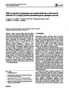
2 Materials and methods 2.1 Material In this experiment, the nickel based superalloy K417G was used as the substrate with a dimension of 25.4 mm in diameter and 6 mm in thickness. The coating materials were commercially available NiCoCrAlYTa powder (Amdry 997, Sulzer-Metco, USA) with particle size of 15 μm – 45 μm (Fig. 1a) and ZrO2 –7 wt.%Y2O3
Fig. 1 The morphologies of powders: (a) NiCoCrAlYTa used in metallic bond coating; (b) 7YSZ used in ceramic top coating.
547
(7YSZ) powder (AMPERIT 827, H C Starck, Germany) with particle size of 10 μm – 45 μm (Fig. 1b). In order to increase adherence capability, the superalloy substrate was grit-blasted. After grit blasting, a NiCoCrAlYTa bond coating with a thickness of about 50 μm ± 10 μm was firstly sprayed on the superalloy substrate by using the High Velocity Oxygen Fuel (HVOF) spraying system (K2, GTV, Germany), and then a 7YSZ ceramic coating with a thickness of about 300 μm ± 10 μm was sprayed on the bond coating by means of Air Plasma Spraying (APS) system (MF-P 1000, GTV, Germany). 2.2 Laser process A pulsed Nd:YAG laser (XL-1000Y, China) with maximum power of 1000 W and wavelength of 1064 nm and Gaussian distribution was used for processing different shaped bionic structures on specimens’ surface. The laser process parameters were as follows: the input energy of 6.5 J, the pulse duration of 7 ms, the laser spot diameter of 1.5 mm. The surface images of the as-sprayed and bionic specimens with different kinds of bionic units are shown in Fig. 2. 2.3 Erosion test The solid particle erosion test was performed on the erosion experiment equipment which is self-modified from the sand-blasting machine according to GE
Fig. 2 The surface images of specimens: (a) as-sprayed specimen; (b) dot bionic specimen; (c) striation bionic specimen; and (d) grid bionic specimen.
548
Journal of Bionic Engineering (2018) Vol.15 No.3
specification E50TF121, as schematically illustrated in Fig. 3. It consists of the following components: air compressor, pressure control valve, particle container, specimen holder, and collector. Aluminum oxide particles (~50 μm) with irregular polygonal shapes, shown in Fig. 4, were used as the erosive media. This particular size alumina powder has been used as the erosive media by other researcher[38] because of its hardness, wear resistance, and thermal stability at high temperature. The test specimens were held at the impact angle of 20˚ ± 2˚ to the axis of blast nozzle. The distance from the nozzle exit to coating surface was 101.6 mm. The particles accelerate through the nozzle and then finally hit the specimen which is mounted on the specimen holder. Compressed air (pressure set as 0.25 MPa) was used for the power to spray erosive particles on the surface of coatings. The erosion resistance of TBCs was evaluated
Fig. 3 Schematic diagram of the solid particle erosion test: 1. air compressor, 2. pressure control valve, 3. particle container, 4. specimen holder, 5. collector.
Fig. 4 SEM image of erosive particles.
through erosive mass loss, which was obtained by weighing the specimen before and after each experiment of erosion test using a precision electronic balance with 1×10⁻⁴ g accuracy. The measured values of erosive mass loss were the average of three individual experimental results. 2.4 Characterization The microstructures of the powders, as-sprayed and bionic TBCs were characterized via a Scanning Electron Microscopy (SEM). Image analysis software was used to estimate the porosity of coatings and measure the depth of bionic unit. The porosity reported is the average of ten values scanned from different areas in the cross-sectional coating. The erosive surface morphologies of the coatings were analyzed via a 3D surface Profiler. The phase compositions of the powder, as-sprayed and bionic specimens were identified using the X-ray diffractometer (XRD), employing Cu Kα radiation. The X-ray generator operated at 40 kV and 100 mA at a 2θ range of 20˚ – 90˚ with scanning speed of 10 ˚·min−1. In order to identify the existence of monoclinic zirconia, a slow scan at the 2θ range of 27˚ – 33˚ with scanning speed of 2 ˚·min−1 was conducted. The microhardness test was conducted on the Vickers hardness tester (MH-5D, China) under a load of 100 g for 10 s. The hardness values in the polished cross section of bionic TBCs were averaged by fifteen points of measurement.
3 Results and discussion 3.1 Microstructure Fig. 5 presents the surface morphologies of the as-sprayed and the bionic TBCs. It can be observed that the coatings present the obviously different surface morphologies. The as-sprayed coating, shown in Fig. 5a, exhibits some microcracks, a few incomplete melted feedstock, pores, splats, and protrusions, which are the typical characteristics of plasma-sprayed ceramic coatings and cause a rough surface. The microcracks formed over the ceramic top coating were due to induced thermal stress caused by rapid cooling (cooling rates in the range of 106 K·s−1– 108 K·s−1)[39]. The surface morphologies of dot and striation bionic specimens are presented in Figs. 5b and 5c, respectively. The grid bi-
Zhang et al.: Effect of Bionic Unit Shapes on Solid Particle Erosion Resistance of ZrO2–7wt%Y2O3 Thermal Barrier Coatings Processed by Laser
onic specimen reveals the similar surface morphology with the striation bionic specimen. After the bionic coupled laser treatment, the surface of the bionic units becomes smoother than that of the as-sprayed coating and the characteristics of pores, voids, microcracks, protrusions, unmelted and partially melted particles in the as-sprayed coatings are eliminated. However, the TBCs processed by BCLR treatment form radial segmented cracks due to the small molten pool, volume shrinkage, the relaxation of residual stresses during the rapid and non-uniform cooling down of molten zirconia to room temperature, and the large and localized temperature gradient along the radial direction[14,40]. Fig. 5d shows the top surface microstructure of bionic unit at a higher magnification. It can be observed that the surface becomes denser with fine crystalline grains. It is mainly because of complete recrystallization of the as-sprayed coating under the condition of the ultrahigh laser heating and cooling rate. The cross-sectional morphologies of the bionic TBCs are presented in Fig. 6. After the BCLR process, a modified layer presenting approximate inverted parabolic curve can be called bionic unit (Fig. 6a), which has the depth of approximately 160 μm. After the laser beam incidence on the surface of TBCs, the material will be remelted at a high heating rate, and then the process of solidification leads to the formation of bionic unit.
Fig. 5 Surface morphologies of specimens: (a) as-sprayed coating; (b) dot bionic unit; (c) striation bionic unit; (d) top surface of bionic unit.
549
Further measurements by image analysis reveal that the porosity of as-sprayed coating is 14.2% ± 4.0%, the porosity of bionic unit is only 0.4% ± 0.1% after the BCLR process, as presented in Fig. 7. During the interaction between laser beam and materials, the light energy converts into thermal energy so that ceramic coatings are heated rapidly. Once the surface temperature reaches the melting point Tm, the isothermal surface T = Tm begins to spread toward the inner of as-sprayed coating so that the molten pool forms. Since the spatial intensity profile of the laser beam follows a Gaussian distribution, a large thermal gradient tends to develop between the centre and edge of the molten pool, which further gives rise to surface tension gradient and attendant Marangoni flow[41]. The combined effect of the present torque and Marangoni flow tends to rotate the liquid material in the molten pool. In this case, the gas can easily escape from the coating, thus contributing to the formation of a low porosity bionic unit. Additionally, owing to the melting and rapid solidification of molten pool, the vertical cracks were formed in the bionic unit, which have proven to be very beneficial to accommodate the thermal stress and mismatch of stresses[42]. It is worthy to note that the center of the bionic unit presents the concave morphology from the Fig. 6a. It can be explained that the excessive energy leads to the material evaporation and removal. Fig. 6b shows the microstructures of bionic unit at a higher magnification, the bionic unit shows a fully dense columnar crystal
Fig. 6 Cross-sectional morphologies of the bionic specimen: (a) overview of unit; (b) microstructure in unit center; (c) microstructure in transition zone; (d) microstructure in as-sprayed region.
550
Journal of Bionic Engineering (2018) Vol.15 No.3
Fig. 7 Microscopic images of TBCs cross-section for porosity measurement: (a) as-sprayed coating; (b) bionic unit.
structure. Due to the synergistic effect of temperature gradient and solidification rate during laser treatment, a columnar crystal structure is formed in the direction of heat flow, which is a typical directional solidification. Fig. 6c shows the microstructure of the transition zone between bionic unit and as-sprayed region. Even though there is not enough energy spreading to the transition zone, it still consists of a structure much denser than that of the as-sprayed region. It can be observed from Fig. 6d, the ceramic coating (as-sprayed region) has a typical lamellar structure which has been formed by the accumulating flattened splats. In addition, due to the insufficient overlapping among the adjacent splats and the entrapped gas during the plasma spraying process, the pores and voids are formed in the ceramic coating. 3.2 Phase composition Fig. 8 exhibits the XRD patterns on the original ceramic powder, the as-sprayed and the bionic TBCs at the 2θ range of 20˚ – 90˚. The phases of YSZ ceramic powder consist of primary tetragonal zirconia (t-ZrO2) and cubic zirconia (c-ZrO2). It can also be observed from Fig. 9 that a small amount of monoclinic zirconia (m-ZrO2) is detected on the 7YSZ ceramic powder at the 2θ range of 27˚ – 33˚, while it disappears after the air plasma spraying and the BCLR process. Under the action of heating and melting by plasma flame during air plasma spraying, all phases in the powder changed to non-equilibrium tetragonal zirconia (t'-ZrO2) and c-ZrO2. The disappearance of m-ZrO2 during the plasma spraying process was caused by phase transformations that changed m-ZrO2 into t-ZrO2 above 800 ˚C, and then t-ZrO2 changed into c-ZrO2 at 2370 ˚C[43]. On the one hand, the addition of Y2O3 can stabilize the crystalline structure of ZrO2 and further inhibit the phase trans-
formation of ZrO2. On the other hand, due to the rapid cooling and solidification rate of air plasma spraying, the phase transformation of ZrO2 is limited. Therefore, no m-ZrO2 phase is found in the as-sprayed specimen. Moreover, the phase composition of bionic specimen consists of prominent t'-ZrO2 and c-ZrO2, which shows no obvious difference in the as-sprayed one. Therefore, the BCLR process has no effect on the phase transformation of TBCs. The transformation of t'-ZrO2 to m-ZrO2 was restrained due to the high cooling rate of laser process[22] and local homogeneities in Y2O3 distribution because of remelting and then solidification during the laser process[14]. As a result, the m-ZrO2 phase is unfound in bionic specimen. 3.3 Microhardness The average microhardness of the as-sprayed
Fig. 8 XRD diffraction patterns in the entire range: (a) 7YSZ ceramic powder; (b) as-sprayed specimen; (c) bionic specimen.
Fig. 9 XRD diffraction patterns in the low 2θ range: (a) 7YSZ ceramic powder; (b) as-sprayed specimen; (c) bionic specimen.
Zhang et al.: Effect of Bionic Unit Shapes on Solid Particle Erosion Resistance of ZrO2–7wt%Y2O3 Thermal Barrier Coatings Processed by Laser
coating and bionic unit is depicted in Fig. 10. It is obvious that microhardness of the as-sprayed coating is enormously improved after the BCLR treatment. The average microhardness of the bionic unit is over 1492 HV0.1, which is increased by 81%, in contrast to that of the as-sprayed coating with the average value of 824 HV0.1. The higher microhardness of the bionic unit is mainly because of the elimination of pores and voids and the formation of dense columnar crystal structure after BCLR treatment. 3.4 Erosion resistance Fig. 11 and Table 1 illustrate the result of the erosion experiment of the as-sprayed and bionic TBCs with different kinds of bionic unit. The erosive mass loss of the as-sprayed specimen is higher than that of the corresponding bionic ones under the same condition. That is to say, the erosion resistance of bionic specimens with different kinds of bionic unit is better than that of the as-sprayed ones. The erosive mass loss nearly has a linear increment as the time increases for both assprayed and bionic specimens. The erosion resistance varies with the bionic unit shape. Before the erosion time of 420 s, the erosion resistance of the bionic specimens with grid bionic unit is the best, which improves by more than 22% than the as-sprayed specimens; the second is the striation, which improves by 21%; and the third is the dot, which improves by only 1%. The results could be explained by the following reasons: on the one hand, due to the denser microstructure and higher microhardness of the bionic unit, it is hard to damage and fracture the ceramic surface for the impact particles. It is reported that the splat ejection is the dominant material removal mechanism in the dense coatings. The lower porosity, coupled with the energy absorption capacity and the high bond strength of the bionic unit, has made splat ejection more difficult[44]. Therefore, the denser bionic specimens have better erosion resistance than the as-sprayed specimens. On the other hand, various shapes of bionic units affect the erosion resistance of the specimens. The more the dense bionic unit are, the better the erosion resistance of the specimens is. The dot bionic specimens have the least bionic units, which therefore presents the worst erosion resistance. When the erosive particles impact on the ceramic coating, pores in the coating may
551
act as stress raisers that facilitate crack initiation. Cracks could easily propagate by connecting pores with high stress concentration, leading to eventual surface failure of the coatings[44]. However, the low porosity bionic units can relieve the negative effect in this study. Hence, the erosion cracks are much more difficult to propagate through the interconnected dense regions for striation and grid bionic specimens than those isolated dense regions for dot bionic specimen. This minimizes the material removal and results in the better erosion resistance of the striation and grid bionic specimens than that of the dot bionic specimen. In addition, the various shapes of bionic units lead to the difference in the roughness of the bionic specimens, which causes the different erosion resistance of the specimens. Zhang et al. investigated the effect of coating roughness on the erosion resistance, and found that the erosion rate increased with the increasing of ceramic coating roughness[38]. The surface of the bionic specimens becomes smoother due to the existence of the bionic units. The more bionic units are, the less roughness is. This also explains why
Fig. 10 The microhardness of as-sprayed coating and bionic unit.
Fig. 11 Cumulative erosive mass loss curves of the as-sprayed and bionic specimens.
Journal of Bionic Engineering (2018) Vol.15 No.3
552
Table 1 Cumulative erosive mass loss results of the as-sprayed and bionic specimens Specimen Time (s)
As-sprayed specimen
Dot bionic specimen
Striation bionic specimen
Grid bionic specimen
30
11.6
10.4
9.3
7.9
60
17.5
15.4
13.6
12.8
90
22.1
20.8
18.1
16.3
120
26.5
25.6
22.4
19.9
150
31.1
30.3
25.9
23.6
180
35.5
33.9
29.7
26.7
210
40.0
39.0
33.4
29.6
240
44.5
42.2
36.9
33.0
270
48.7
46.2
40.0
36.4
300
52.7
51.0
42.4
39.8
360
60.6
59.2
48.0
46.5
420
68.4
67.8
53.9
53.4
480
76.9
75.3
59.3
60.1
540
85.1
83.5
64.8
67.1
600
92.7
90.8
70.7
72.3
the erosion resistance of the striation and grid bionic specimens is better than that of the dot bionic specimen. However, after the erosion time of 420 s, the erosion resistance of the bionic specimens with striation bionic unit is even better than that of the bionic specimens with grid bionic unit, which will be explained in details later. 3.5 Erosion morphology and mechanism Fig. 12 shows the erosive surface morphology and the three dimensional morphology of plasma-sprayed TBCs at the end of erosion test. The erosive surface presents a characteristic of obvious fracture and spallation shown in Fig. 12a. There are some furrows and erosion pits produced on the surface of as-sprayed coating, the areas of the splats decreased, and most splats seemed possibly damaged into smaller pieces. In addition, the protrusions on the surface of as-sprayed specimen disappeared under the action of erosive particles. There is also evidence of brittle cracking, which finally led to the fragmentation of coating. The three dimensional photograph can vividly describe the surface morphology after erosion, as depicted in Fig. 12b. When the erosive particles impacted on the protrusions, both the shear stress and normal stress acted on the coating surface[45]. Under the action of shear stress, the coating surface was cut by the erosive particles, finally the deep furrows were produced and the splats fractured into
smaller piece. Since the impact of erosive particles against the coating surface was intermittent during erosion test, the coating surface withstood the cyclic loading and unloading under the impact of erosive particles. As a result, the coating surface underwent the compressive-compressive pulsating load, and the normal stress acted on the coating surface under the action of pulsating load, which finally led to the formation of erosion pits and the spallation of the coating[46]. Owing to the impact of erosive particles on the coating surface, the central and radial cracks developed at the impact region[22,44].Under the repeating action of erosive particles, the microscopic cracks on the coating surface initiated and further propagated, the parallel cracks between lamella and the vertical cracks across the coating developed, finally the crack reached the critical size and the macroscopic cracks formed, which lead to the spallation of the coating. Therefore, the fracture and spallation of brittle ceramic coating are responsible for the erosion failure of the plasma-sprayed TBCs.
Fig. 12 Typical erosive surface morphologies of plasma-sprayed TBCs: (a) as-sprayed coating; (b) 3D morphology.
Zhang et al.: Effect of Bionic Unit Shapes on Solid Particle Erosion Resistance of ZrO2–7wt%Y2O3 Thermal Barrier Coatings Processed by Laser
Fig. 13 shows the erosion morphologies of bionic specimens with different kinds of bionic unit under the same erosive condition. The bionic specimens present evident different morphologies compared with the as-sprayed one. The segment size on the surface of bionic units with different shapes after erosion test is smaller than that of the bionic specimens before erosion test, which means that the initial segments are broken into smaller pieces by erosive particles. There are no significant features of spallation except for the deep erosive groove in the part of the dot bionic unit zone towards the erosion direction (Fig. 13a), and additionally the bionic unit gradually rises from the coating (Fig. 13b). By contrast, the spallation characterization in the striation unit zone (Fig. 13c) is obvious, which is
553
mainly occurred in the overlapping area between the adjacent laser irradiation. Besides, there is deep groove towards the erosion direction as shown in Fig. 13d. Due to the biggest overlapping area of laser radiation in the grid unit zone, the extent of the spallation is the most serious (Fig. 13e), many deep grooves distribute in the edge of the laser radiation region as depicted in Fig. 13f. This phenomenon is consistent with the erosive result shown in Fig. 11 and further indicates that the erosion resistance of striation bionic specimen is better than that of grid bionic specimen during the later period of erosion process. In addition, the concave-shape bionic unit is conductive to the improvement of solid particle erosion resistance. The particle impact velocity is an important
Fig. 13 The erosive surface morphologies of bionic specimens: (a) specimen with dot bionic unit; (b) 3D morphology of (a); (c) specimen with striation bionic unit; (d) 3D morphology of (c); (e) specimen with grid bionic unit; (f) 3D morphology of (e).
Journal of Bionic Engineering (2018) Vol.15 No.3
554
impact variable which influences the erosion behavior of materials. The erosion resistance can be expressed by[44]:
E = kv n ,
(1)
where E is the erosion rate, k is a constant related to the impact angle and particle size, v is the impact velocity, and n is velocity exponent. It is obvious that the erosion rate increases enormously with the increment of the impact velocity. As reported by Han et al., compared with the smooth surfaces, the particle impacts on the groove type surface were occurring at the lower impact velocities which were obtained by the FLUENT postprocessing system[27]. Based on the above-mentioned analyses, it can be inferred that the impact velocity of the concave-shape bionic unit is lower than that of the as-sprayed region, i.e., the erosion resistance of bionic specimen is better than that of as-sprayed specimen. This explains why the concave-shape bionic unit can improve the erosion resistance. Fig. 14 presents the high magnification photograph of erosive surface on the bionic unit, the clear and deep furrows are found on the erosive unit surface, which indicates that the brittle and some ductile erosion are the main erosion failure mechanisms of bionic TBCs. For one thing, the laser processed coatings have the good ability of resisting the crack propagation and show excellent erosion resistance on account of high adhesion strength, high hardness, and minimal defects[21]. For another, it is well known that fracture toughness is usually considered as the decisive indicator of the erosive wear resistance of thermal barrier coatings[47]. Moreover, the post-coating processing which consists of flame, laser and vacuum furnace heating can modify the microstructure, reduce its porosity, increase its plasticity and fracture toughness and improve the bond strength[48]. Therefore, the erosion resistance of bionic specimens after BCLR treatment is improved and the mechanism of erosive wear can preferentially change from brittle to plastic by laser treatment and thus exhibit plastic erosion to some extent. Fig. 15 shows the diagrammatic sketch of the erosion process of bionic specimens. When the specimen was impacted by erosive particles, the surface was coarse and unflat in microscopic view before erosion test, which can be seen from Fig. 15a. During the erosion
process, the as-sprayed region and the unit on the coating surface are eroded at the same time. For the bionic specimens, the as-sprayed region is relatively higher than the bionic unit in the most areas. Therefore, the as-sprayed region has the high possibility of being impacted by erosive particles, i.e., the as-sprayed region can easily be damaged by particle impact. The impact of erosive particles can gain the coating cracks and lead to the fracture and fragmentation of individual splats during the early erosion. In addition, erosive mass loss increases with reducing microhardness magnitude. Consequently the as-sprayed region gets severe damage as the erosion test proceeds. The erosion loss area of bionic specimens is the yellow latticed area shown in Fig. 15b. With consuming the as-sprayed region, the surface in the as-sprayed region becomes almost smooth and the bionic unit gradually rises from the coating. The most of the bionic unit is exposed to the erosive particles. Then the bionic unit spalls from its edge under the impact of erosive particles during the later period of erosion test, finally the rugged surface is formed on the bionic specimens, shown in Fig. 15c. Considered as the erosive cycle, it repeats during erosion test. In this work, a bionic structure which is similar with alternately soft and hard structure of desert organisms is formed between the as-sprayed coating and bionic units on the surface. This bionic structure has a desirable advantage of high hardness and low surface roughness, which could reduce erosive mass loss. Therefore, the erosion resistance of bionic specimens is enhanced.
Fig. 14 The erosive surface morphology on the bionic unit.
Zhang et al.: Effect of Bionic Unit Shapes on Solid Particle Erosion Resistance of ZrO2–7wt%Y2O3 Thermal Barrier Coatings Processed by Laser
555
specimens exhibited the better erosion resistance, while the erosion resistance of the dot bionic specimen was slightly improved. The higher hardness and denser microstructure of bionic units were the main reasons for enhancing the solid particle erosion resistance. The concave-shape bionic unit could improve the erosion resistance by decreasing the impact velocity. (3) Under the action of erosive particles, the surface of as-sprayed coating was characterized by furrows, erosion pits, small splats, and cracks. Under the synergistic action of the shear stress and normal stress on the protrusive coating surface, the fracture and spallation of the brittle ceramic coatings were responsible for the erosion failure of the as-sprayed TBCs. (4) The segment size on the surface of bionic units with different shapes became smaller after erosion test. The spallation of segmented bionic unit occurred in the overlapping area between the adjacent laser irradiation, and the erosive unit surface presented the clear and deep furrows, which revealed that the erosion failure mechanism of bionic TBCs was dominated by brittle and some ductile erosion. Fig. 15 The sketch map of erosion test: (a) the specimen before erosion test; (b) early period of erosion test and (c) later period of erosion test.
4 Conclusion (1) The as-sprayed coating was characterized by the typical lamellar stacking structure, some pores and voids, microcracks, splats, and protrusions. After the BCLR process, the surface of the bionic units became smoother than that of the as-sprayed coating and the defects in the as-sprayed coating were eliminated. The bionic unit showed the dense columnar crystal structure because of the synergistic effects of temperature gradient and solidification rate during laser treatment, which was a typical directional solidification. The average microhardness of the bionic unit was over 1492 HV0.1, which was increased by 81%, in contrast to that of the as-sprayed coating with the average value of 824 HV0.1. (2) Erosion tests indicated that the bionic specimens had better solid particle erosion resistance than the as-sprayed specimen. The shape of bionic units could enormously influence the erosion resistance. In terms of the shapes of bionic unit, the striation and grid bionic
Acknowledgment This work is supported by Science and Technology Project of Guangdong Province (2014B050502008), Science and Technology plan projects of Guangdong Province (2017A070702016, 2017A070701027), Guangzhou Science and Technology Program key projects (201510010095), Natural Science Foundation of Guangdong Province (2016A030312015), the National Natural Science Foundation for Youth (51501044), and 111 Project of China (B16020).
References [1]
Li C J, Li Y, Yang G J, Li C X. A novel plasma-sprayed durable thermal barrier coating with a well-bonded YSZ interlayer between porous YSZ and bond coat. Journal of Thermal Spray Technology, 2012, 21, 383–390.
[2]
Liu C B, Zhang Z M, Jiang X L, Liu M, Zhu Z H. Comparison
of
thermal
shock
behaviors
between
plasma-sprayed nanostructured and conventional zirconia thermal barrier coatings. Transactions of Nonferrous Metals Society of China, 2009, 19, 99–107. [3]
Ghasemi R, Vakilifard H. Plasma-sprayed nanostructured
556
Journal of Bionic Engineering (2018) Vol.15 No.3
YSZ thermal barrier coatings: Thermal insulation capability and adhesion strength. Ceramics International, 2017, 43, [4]
8556–8563.
Microstructure and thermal shock resistance of the peg-nail
Fan X L, Xu R, Kikuchi M. Fracture of thermal barrier
structured TBCs treated by selective laser modification.
coating with multiple surface cracks and delaminations: Interlayer effect. Journal of Central South University, 2014, [5]
21, 2579–2583.
investigation on erosion behavior of nanostructured 7YSZ coatings at elevated temperature. Surface & Coatings
In-situ digital image correlation and finite element analyses.
[9]
M
P,
Harder
B
J,
Wolfe
D
E.
Acta Materialia, 2017, 128, 54–63.
Process-structure-property
durability of plasma spray-physical vapor deposition
interfacial delamination of thermal barrier coating system
(PS-PVD) thermal barrier coatings. Surface & Coatings
with double ceramic layers. Applied Surface Science, 2016,
Technology, 2016, 297, 11–18.
relations
for
the
erosion
[17] Bousser E, Martinu L, Klemberg-Sapieha J E. Solid particle
Foroushani M H, Shamanian M, Salehi M, Davar F. Porosity
erosion mechanisms of protective coatings for aerospace
analysis and oxidation behavior of plasma sprayed YSZ and
applications. Surface & Coatings Technology, 2014, 257,
YSZ/LaPO4 abradable thermal barrier coatings. Ceramics
165–181.
International, 2016, 42, 15868–15875. [8]
Technology, 2016, 299, 129–134. [16] Schmitt
Xu R, Fan X L, Wang T J. Mechanisms governing the
370, 394–402. [7]
Applied Surface Science, 2014, 317, 598–606. [15] Qu Z L, Cheng X M, Wu J G, He R J, Pei Y M, Fang D N. An
Bumgardner C, Croom B, Li X D. High-temperature delamination mechanisms of thermal barrier coatings:
[6]
& Coatings Technology, 2015, 282, 129–138. [14] Chang F, Zhou K S, Tong X, Xu L P, Zhang X F, Liu M.
Tsai P C, Tseng C F, Yang C W, Kuo I C, Chou Y L, Lee J W.
[18] Cernuschi F, Guardamagna C, Capelli S, Lorenzoni L, Mack D E, Moscatelli A. Solid particle erosion of standard and
Thermal cyclic oxidation performance of plasma sprayed
advanced thermal barrier coatings. Wear, 2016, 348, 43–51.
zirconia thermal barrier coatings with modified high
[19] Ramanujam N, Nakamura T. Erosion mechanisms of
velocity oxygen fuel sprayed bond coatings. Surface &
thermally sprayed coatings with multiple phases. Surface &
Coatings Technology, 2013, 228, S11–S14.
Coatings Technology, 2009, 204, 42–53.
Doleker K M, Karaoglanli A C. Comparison of oxidation
[20] Schmitt M P, Stokes J L, Gorin B L, Rai, A K, Zhu D M,
behavior of YSZ and Gd2Zr2O7 thermal barrier coatings
Eden T J, Wolfe D E. Effect of Gd content on mechanical
(TBCs). Surface & Coatings Technology, 2017, 318,
properties and erosion durability of sub-stoichiometric
198–207.
Gd2Zr2O7. Surface & Coatings Technology, 2017, 313,
[10] Loghman-Estarki M R, Razavi R S, Edris H, Bakhshi S R,
177–183.
Nejati M, Jamali H. Comparison of hot corrosion behavior
[21] Tsai P C, Lee J H, Chang C L. Improving the erosion
of nanostructured ScYSZ and YSZ thermal barrier coatings.
resistance of plasma-sprayed zirconia thermal barrier
Ceramics International, 2016, 42, 7432–7439.
coatings by laser glazing. Surface & Coatings Technology,
[11] Pakseresht A H, Javadi A H, Ghasali E, Shahbazkhan A,
2007, 202, 719–724.
Shakhesi S. Evaluation of hot corrosion behavior of plasma
[22] Wang D S, Tian Z J, Shen L D, Liu Z D, Huang Y H. Effects
sprayed thermal barrier coatings with graded intermediate
of laser remelting on microstructure and solid particle
layer and double ceramic top layer. Surface & Coatings
erosion characteristics of ZrO2-7wt%Y2O3 thermal barrier
Technology, 2016, 288, 36–45.
coating
[12] Loghman-Estarki M R, Nejati M, Edris H, Razavi R S,
prepared
by
plasma
spraying.
Ceramics
International, 2014, 40, 8791–8799.
Jamali H, Pakseresht A H. Evaluation of hot corrosion
[23] Wang Z Z, Gao K, Sun Y H, Zhang Z H, Zhang S Y, Liang Y
behavior of plasma sprayed scandia and yttria co-stabilized
H, Li X J, Ren L Q. Effects of bionic units in different scales
nanostructured thermal barrier coatings in the presence of
on the wear behavior of bionic impregnated diamond bits.
molten sulfate and vanadate salt. Journal of the European
Journal of Bionic Engineering, 2016, 13, 659–668.
Ceramic Society, 2015, 35, 693–702.
[24] Cong D L, Zhou H, Ren Z N, Zhang Z H, Zhang H F, Meng
[13] Nejati M, Rahimipour M R, Mobasherpour I, Pakseresht A H.
C, Wang C W. The thermal fatigue resistance of H13 steel
Microstructural analysis and thermal shock behavior of
repaired by a biomimetic laser remelting process. Materials
plasma sprayed ceria-stabilized zirconia thermal barrier
& Design, 2014, 55, 597–604.
coatings with micro and nano Al2O3 as a third layer. Surface
[25] Wang C W, Zhou H, Zhang Z H, Zhao Y, Zhang P, Cong D L,
Zhang et al.: Effect of Bionic Unit Shapes on Solid Particle Erosion Resistance of ZrO2–7wt%Y2O3 Thermal Barrier Coatings Processed by Laser Meng C, Tan F X. Tensile property of a hot work tool steel prepared by biomimetic coupled laser remelting process with different laser input energies. Applied Surface Science,
557
suspension plasma spray. Journal of Thermal Spray Technology, 2016, 26, 108–115. [38] Zhang X F, Zhou K S, Zhang J F, Han T, Song J B, Liu M. Erosion failure mechanism and model establishment of
2012, 258, 8732–8738. [26] Huang H, Zhang Y, Ren L Q. Particle erosion resistance of bionic samples inspired from skin structure of desert lizard, laudakin stoliczkana. Journal of Bionic Engineering, 2012, 9,
thermal barrier coatings based on roughness. Journal of Inorganic Materials, 2014, 29, 294–300. [39] Dhineshkumar S R, Duraiselvam M, Natarajan S, Panwar S S, Jena T, Khan M A. Enhancement of strain tolerance of
465–469. [27] Han Z W, Zhang J Q, Ge C, Wen L, Ren L Q. Erosion
functionally graded LaTi2Al9O19 thermal barrier coating
resistance of bionic functional surfaces inspired from desert
through ultra-short pulse based laser texturing. Surface &
scorpions. Langmuir, 2012, 28, 2914–2921.
Coatings Technology, 2016, 304, 263–271.
[28] Han Z W, Yin W, Zhang J Q, Jiang J L, Mu S C, Ren L Q.
[40] Batista C, Portinha A, Ribeiro R M, Teixeira V, Costa M F,
Erosion-resistant surfaces inspired by tamarisk. Journal of
Oliveira C R. Surface laser-glazing of plasma-sprayed
Bionic Engineering, 2013, 10, 479–487.
thermal barrier coatings. Applied Surface Science, 2005, 247,
[29] Ren L Q, Liang Y H. Biological couplings: Classification and
characteristic
rules.
Science
In
China
Series
E-Technological Sciences, 2009, 52, 2791–2800. and
implementation
mode.
[41] Zhang Z H, Zhou H, Ren L Q, Tong X, Shan H Y, Li X Z. Surface morphology of laser tracks used for forming the
[30] Ren L Q, Liang Y H. Biological couplings: Function, characteristics
313–319.
non-smooth biomimetic unit of 3Cr2W8V steel under
Science
different processing parameters. Applied Surface Science,
[31] Zhang P P, Zhang Z H, Zhang B Y, Tong X, Liang Y H, Li X
[42] Li G R, Yang G J, Li C X, Li C J. Strain-induced multiscale
J, Ren L Q. Dimension, hardness and prediction models of
structural changes in lamellar thermal barrier coatings.
bionic coupling units processed by laser for gray cast iron.
Ceramics International, 2017, 43, 2252–2266.
China-Technological Sciences, 2010, 53, 379–387.
Journal of Laser Applications, 2016, 28, 022007. [32] Zhang B Y, Zhang Z H, Liang Y H, Yan Q Q, Ren L Q. Effects of laser parameters on the geometrical characteristics of peg-shaped bionic coupling unit. Optics & Laser Technology, 2014, 64, 184–194.
2008, 254, 2548–2555.
[43] Zhang X F, Zhou K S, Chang F, Song C, Deng C M, Liang S Y. Yttria-stabilized-zirconia hollow spheres prepared by atmospheric plasma spray. Particuology, 2014, 14, 57–62. [44] Ramachandran
C
S,
Balasubramanian
V,
Ananthapadmanabhan P V. Erosion of atmospheric plasma
[33] Zhang Z H, Ren L Q, Zhou T, Han Z W, Zhou H, Chen L,
sprayed rare earth oxide coatings under air suspended
Zhao Y. Optimization of laser processing parameters and
corundum particles. Ceramics International, 2013, 39,
their effect on penetration depth and surface roughness of
649–672.
biomimetic units on the surface of 3Cr2W8V steel. Journal of Bionic Engineering, 2010, 7, S67–S76.
Aerodynamic roughness of cultivated soil and its influences
[34] Shen W, Wang F C, Fan Q B, Ma Z. Effects of defects on the effective thermal conductivity of thermal barrier coatings. Applied Mathematical Modelling, 2012, 36, 1995–2002. [35] Lu L, Wang F C, Ma Z, Fan Q B. Anisotropic effect of splat interface on thermal conductivity of plasma sprayed YSZ coating. Surface & Coatings Technology, 2013, 235, 596–602.
on soil erosion by wind in a wind tunnel. Soil & Tillage Research, 2004, 75, 53–59. [46] Wang R Z. Overview on the shot peening principle and its strengthening mechanisms for metallic materials. China Surface Engineering, 2012, 25, 1–9. [47] Houdkova S, Kasparova M. Experimental study of indentation fracture toughness in HVOF sprayed hardmetal
[36] Nicholls J R, Deakin M J, Rickerby D S. A comparison between the erosion behaviour of thermal spray and electron beam physical vapour deposition thermal barrier coatings. Wear, 1999, 233-235, 352–361. R.
Erosion
performance
coatings. Engineering Fracture Mechanics, 2013, 110, 468–476. [48] Guo D Z, Li F L, Wang J Y, Sun J S. Effects of post-coating processing on structure and erosive wear characteristics of
[37] Mahade S, Curry N, Björklund S, Markocsan N, Nylén P, Vaßen
[45] Zhang C L, Zou X Y, Gong J R, Liu L Y, Liu Y Z.
of
gadolinium
zirconate-based thermal barrier coatings processed by
flame and plasma spray coatings. Surface & Coatings Technology, 1995, 73, 73–78.