Praggya Agnihotry*, R.P.Agarwal**. *(Research Scholar, Department of ECE, Shobhit University, Meerut, India). ** (Academic Advisor, Shobhit University, ...
Praggya Agnihotry Int. Journal of Engineering Research and Applications ISSN : 2248-9622, Vol. 5, Issue 5, ( Part -3) May 2015, pp.154-156 RESEARCH ARTICLE
www.ijera.com
OPEN ACCESS
Effect of Doping of MLGNR on Propagation Delay of a DriverInterconnect-Load system Praggya Agnihotry*, R.P.Agarwal** *(Research Scholar, Department of ECE, Shobhit University, Meerut, India) ** (Academic Advisor, Shobhit University, Meerut, India) ABSTRACT Nowadays multi layer GNR (MLGNR) is used in nano scale VLSI interconnection. In this research paper study has been done on two variants of MLGNR, one neutral MLGNR (means with no doping) and second intercalated doped MLGNR, in terms of propagation delay. The test circuit which has been used to check the propagation delay is a Driver-interconnect-load system which is using CMOS, short gate (SG) FinFET, independent gate (IG) FinFET, and low power (LP) FinFET as driver and load circuits at 16 nm. Keywords - CMOS , Driver-interconnect-load system , FinFET , Multi layer GNR. drivers and loads. The work has been performance at 16 nm. I. INTRODUCTION In past some work has been done by the The paper has four sections, first section gives brief researchers on neutral and intercalated doped about the aim of work, second section gives the RLC MLGNR [1][2]. In neutral MLGNR layers are model of MLGNR, third section presents result and separated with a distance of 0.34 nm, if a MLGNR is forth section is conclusion of work. doped with AsF5 its conductivity increases reason behind that is due to intercalation doping density of carriers increases due to which mean free path II. RLC MODEL OF MLGNR increases [3]. Also the inter layer spacing increases due to doping [3][4].
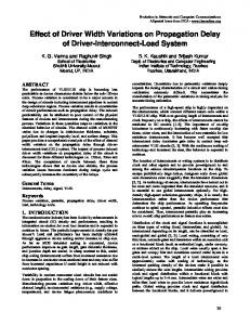
Fig. 1 Schematic view of neutral multilayer GNRs [2] Fig. 3: RLC circuit for MLGNR [7]
Fig. 2 Schematic view of two types of intercalated GNR s1 and s2 are the layer spacing between two adjacent graphene layers. In stage-2 AsF5 intercalated graphite, s1 = 0.335 nm and s2 = 0.815 nm [5]. Conductance of MLGNR can also be increased by making the edges of GNR specular. But in this work only intercalation doping has been considered which makes EF = 0.6eV and mean free path 1.03 µm. For a neutral MLGNR mean free path is 0.4 µm [6]. For a neutral MLGNR EF =0.1eV has been considered in this work. In this paper propagation delay has been studied for both the variants of MLGNR described in previous paragraph. The simulation test circuit is a driverinterconnect-load system which uses four different www.ijera.com
The capacitances and inductances of equivalent model which includes electrostatic capacitance, quantum capacitance and mutual capacitance, kinetic inductance, electrostatic inductance and mutual inductance are given by the expressions [2][8][9]. CQ= NchNlayer 4q2/hvf= NchNlayer * 193.18 aF/μm (1) CE = ε0*w/d aF/μm (2) Cm,layer(j-1, j) = ε0*(w/∂) aF/μm (3) LK= (h/4q2vf)/ NchNlayer = 8.0884/ NchNlayer nH/μm (4) LE =μ0 *(d/w) nH/μm (5) lm,layer (j-1,j) = μ0 *(∂ /w) nH/μm (6) The quantum resistance and scattering resistance is given by [10], RQ= (h/2q2)/NchNlayer= 12.94 KΩ/ NchNlayer (7) RS= RQ / (8)
154 | P a g e
Praggya Agnihotry Int. Journal of Engineering Research and Applications ISSN : 2248-9622, Vol. 5, Issue 5, ( Part -3) May 2015, pp.154-156
www.ijera.com
Where = mean free path. In MLGNR the values of quantum resistance, quantum capacitance and kinetic inductance are depend on number of conducting channels in GNR layers which further depend on width and EF of GNR. The value of conducting channels has been calculated by the expression given by Nasiri in [8].
III.
SET UP AND RESULT
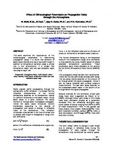
The set up which has been used for simulation is a DIL system with CMOS,SG FinFET, IG FinFET, and LP FinFET driver-load stage.
Fig. 4: Simulation Setup The delay effect has been measured and compared for both variants of MLGNR i.e, for neutral MLGNR and for doped MLGNR. Fig. 5 to Fig. 7 gives the clear comparison between doped and neutral GNR when used with a driver-load stage for super threshold region, near threshold region and sub threshold region. Also Fig. 8 shows the delay variation of GNR for both doped and neutral MLGNR with respect to width for all cases of DIL systems. Fig. 6: Comparison of intercalated doped and neutral MLGNR in near threshold region
Fig. 5: Comparison of intercalated doped and neutral MLGNR in super threshold region www.ijera.com
Fig. 7: Comparison of intercalated doped and neutral MLGNR in sub threshold region 155 | P a g e
Praggya Agnihotry Int. Journal of Engineering Research and Applications ISSN : 2248-9622, Vol. 5, Issue 5, ( Part -3) May 2015, pp.154-156
[2]
[3]
[4]
[5]
[6]
[7]
[8]
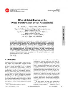
[9] Fig. 8: variation of delay of intercalated doped and neutral MLGNR with respect to width for (a) CMOS driver, (b) SG FinFET driver, (c) IG FinFET driver and (d) LP FinFET driver. [10]
IV.
CONCLUSION
A comparison has been presented between DIL system using doped MLGNR and DIL system with neutral MLGNR and it has been noticed that for DIL system using doped MLGNR propagation delay is less as compared to the DIL system using neutral MLGNR interconnect. And also it has been observed that in near threshold region the comparison effect is not significant.
www.ijera.com
genuine contender or a delusive dream?, in IEDM Tech. Dig, 2008, pp. 201–204. C. Xu, H. Li, and K. Banerjee, Modeling, analysis, and design of graphene nanoribbon Interconnects, IEEE transactions on electron devices, vol. 56, no. 8,2009, pp. 1567-1578. J. E. Fischer and T. E. Thompson, Graphite intercalation compounds,Phys. Today, vol. 31, no. 7, 1978, pp. 36–45. L. R. Hanlon, E. R. Falardeau, and J. E. Fischer, Metallic reflectance of AsF5graphite intercalation compounds, Solid State Commun., vol. 24, no. 5,1977, pp. 377–381. M. S. Dresselhaus and G. Dresselhaus, Intercalation compounds of graphite, Adv. Phys., vol. 51, no. 1, 2002, pp. 1–186. M. K. Majumdar, N. Reddy K., B. K. Kaushik, and S. K. Manhas, Comparison of propagation delay in single and multi-layer graphene nanoribbon interconnects, 2012 5th International conference on computers and devices for communication (CODEC), 2012, pp. 1-4, 17-19 N. Reddy K., M. K. Majumdar, B. K. Kaushik, S. K. Manhas and B. Anand, Dynamic crosstalk effect in multilayer graphene nanoribbon interconnects,2012 International conference on communication, devices and intelligent systems (CODIS), 2012, pp. 472-475, 28-29 S. H. Nasiri, R. Faez, and Md. K. Moravvej-Farshi, Compact Formulae For Number Of Conduction Channels In Various Types Of Graphene Nanoribbons At Various Temperatures, Modern Phys. Lett. B, vol. 26,no. 1, 2011, pp. 1150004-1-1150004-5 C. Berger, Z. Song, X. Li, X. Wu, N. Brown, and W. A. de-Heer, Electronic Confinement and Coherence in Patterned Epitaxial Graphene,Science, vol. 312, no. 5777, 2006, pp. 1191-1196. Naeemi A. and Meindl J., Compact physicsbased circuit models for graphene nanoribbon interconnects, IEEE Transaction on Electron Devices, Vol. 56, 2009, pp. 1822-1833.
.
REFERENCES [1]
C. Xu, H. Li, and K. Banerjee, Graphene nano-ribbon (GNR) interconnects: A
www.ijera.com
156 | P a g e