Effect of Driver Size and Number of Shells on Propagation Delay in MWCNT Interconnects Yograj Singh Duksh*, Brajesh Kumar Kaushik#, Sankar Sarkar$ and Raghuvir Singh$ *Deptt. of Electronics and Instrumentation Engg., Faculty of Engg. and Tech., M.J.P. Rohilkhand University, Bareilly, INDIA # Department of Electronics and Computer Engineering, Indian Institute of Technology-Roorkee, INDIA $ School of Electronics Engineering, Shobhit University, Meerut, INDIA Email {
[email protected];
[email protected];
[email protected];
[email protected]} Abstract— This paper analyzes the effect of driver size and number of shells on propagation delay for Multi-Walled Carbon Nanotubes (MWCNT) interconnect at 22nm technology node. An equivalent circuit model of MWCNT is used for estimation and analysis of propagation delay. The delay through MWCNT and Cu interconnects are compared for various driver sizes and number of MWCNT shells. The SPICE simulation results show that the MWCNT interconnect has lower propagation delay than Cu interconnects. The delay ratio of MWCNT to Cu decreases with increase in length for different driver size and number of MWCNT shells. However, the delay ratio increases with reduction in number of MWCNT shells. MWCNT is considered to be potential alternative to copper interconnects in future. MWCNT provides significant improvement in propagation delay performance over Copper for long (global) interconnects. Keywords- Multi-Walled Carbon Nanotube; Copper; SPICE; Propagation delay; Interconnects.
I.
INTRODUCTION
Carbon nanotubes (CNTs) are graphene sheets rolled up into hollow cylinders. These can be classified as single walled carbon nanotubes (SWCNTs) and multi-walled carbon nanotubes (MWCNTs). SWCNTs has only one shell with diameter ranging from 0.33 to 5.0nm and lengths from 2 to 10nm, whereas MWCNTs has several concentric shells with diameter ranging from several nanometers to tens of nanometers and length of several microns [1]. Each shell of MWCNT can have different chiralities depending on the direction they are rolled up, which implies that the shells in MWCNT are metallic or semiconducting. Recently, some researchers have addressed the issue for implementation of MWCNT based interconnects considering their complexity in both structure and characterization [1, 2]. Interestingly, it has been found that multiple shells in an MWCNT can contribute to conductance if proper end contacts can be made. In [3, 4], properly contacted MWCNTs have been implemented to achieve low resistance with the contribution of inner shells. The purpose of this paper is to analyze the methodology for minimization of propagation delay for various driver size and number of shells. This paper is organized in four sections. MWCNT geometrical structure and its equivalent circuit models are described and discussed in section II. SPICE simulation results are presented and analyzed in section III. Finally, conclusions are drawn in section IV.
II.
MWCNT STRUCTURE AND EQUIVALENT ELECTRICAL MODEL
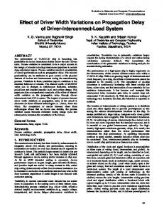
An isolated MWCNT on an infinite ground plane is shown in Figure (1) [1]. The separation between the ground plane and the multi-walled center is H. Dmax and Dmin are the outermost and innermost shell’s diameter respectively. The separation between two adjacent shells is d ≈ 0.34 nm, which is the vander waals gap. A. Number of Channels for MWCNT The number of conducting channels for each shell [1] is 1 (1) N chan / shell = exp(| E i - E F | /K BT ) + 1 subbands
∑
where Ei, is the highest (or lowest) value for the sub-bands below (or above) the Fermi level EF. KB and T are the Boltzmann constant and absolute temperature respectively. The number of channels per shell [5] can be approximated to N chan / shell (D ) ≈ a.D + b, for D>3nm (2) where D is the shell diameter, a=0.0612 nm-1, and b=0.425. The error obtained by approximated form of (2), due to different chiralities, is less than 15% for all values of D. The number of shells are counted from outer to inner as 1, 2,…i,…, n. The ratio (Dmin/Dmax) is equal to 1/2 [1, 4, 5]. Thus, the number of shells n of the MWCNT is − Dmax / 2 ) ⎤ ⎡ (D n = 1 + int ⎢ max ⎥ 2d ⎣ ⎦
(3)
where “int [.]” indicates that only the integer part is taken into account. The diameter of the ith shell is given by [1] Di = Dmax − 2d .(i − 1), for 1≤ i ≥ n (4) The innermost diameter in Figure (1) is Dmin=Dmax -2d.(n-1). MWCNT
Dmin
Dmax
H
d
Ground Plane
Figure (1) MWCNT structure on a ground plane.
978-1-4244-9190-2/11/$26.00 ©2011 IEEE
Note that the ratio of Dmin/Dmax is assumed to be ½, Dmin may be larger than Dmax/2 because Dmax may not be an integer multiple of d. The number of conducting channels of the ith shell is given by [1] N i = a.Di + b (5) Hence, the total number of conducting channels is given by the sum of the conducting channels (Ni) of all the shells. It is note that expressions (2) and (5) are applicable for small voltages, which is valid for interconnect applications [1]. B. Individual Shell Model The equivalent circuit model for an individual shell of an MWCNT can be obtained on the basis of the model of SWCNT [1], which is shown in Figure (2). (i) Resistance: The shell resistance of an MWCNT consists of three parts: quantum contact resistance RQ, scatteringinduced resistance Rs, and imperfect contact resistance Rmc. Scattering induced resistance occurs only when the length of nanotube (shell) is larger than the electron mean free path (MFP). RQ and Rs are intrinsic and Rmc is due to fabrication process. The total shell resistance [1] is given by h h L (6) Rshell = RQ + RS .L = 2 + 2 . 2e N 2e N λ where h/2e2 = 12.9kΩ, and L, λ and N (=a.D+b) are the length, MFP and number of conducting channels of the shell respectively. The imperfect contact resistance Rmc can range from zero to hundreds of kilo-ohms for different growth process. Recently, it has been observed that Rmc in MWCNT could be very small compared to the total resistance [3, 4]. It can be observed from (6) that the value of MFP plays an important role in determining the resistance of the nanotube. It has been proven that the MFP of metallic nanotube is directly proportional to the shell diameter (D). The MFP for metallic MWCNT [4, 9] at room temperature is λ = 250.D (7) (ii) Inductance: There are the two types of inductances for MWCNT i.e the magnetic and kinetic inductances per unit length [6] of a shell are given by Lmagnetic = (μ 2π ). cosh −1 (2 H D ) (8) LK / channel = h 2 × 2e 2vF ≈ 8nH / μm
(9)
LK / shell = LK / channel / N (10) The total kinetic inductance (LK/shell) may decrease from 13 to 1 nH/μm for 3 nm