1228
Biol. Pharm. Bull. 33(7) 1228—1232 (2010)
Regular Article
Vol. 33, No. 7
Effect of Geometrical Structure on the Biodegradation of a ThreeDimensionally Perforated Porous Apatite/Collagen Composite Bone Cell Scaffold Hideyuki HAMADA,a Hiroyuki OHSHIMA,a Atsuo ITO,b William I. HIGUCHI,c and Makoto OTSUKA*,d a
Faculty of Pharmaceutical Sciences, Tokyo University of Science; 2641 Yamazaki, Noda, Chiba 278–8510, Japan: National Institute of Advanced Industrial Science and Technology; Tsukuba, Ibaraki 305–8566, Japan: c Department of Pharmaceutics and Pharmaceutical Chemistry, University of Utah; Salt Lake City, Utah 84112, U.S.A.: and d Research Institute of Pharmaceutical Sciences, Faculty of Pharmacy, Musashino University; Nishi-Tokyo, Tokyo 202–8585, Japan. Received March 3, 2010; accepted April 15, 2010; published online April 26, 2010 b
A Biodegradable artificial bone with inter-connective pores was prepared using a self-setting apatite/collagen composite cement as a cell scaffold for bone regenerative medicine, and investigated as to biocompatibility by X-ray computed tomography (CT) after its implantation into rats. Blocks (APN, APC and ACC) of apatite cement, apatite cement with continuous holes, and apatite/collagen composite cement with continuous holes were prepared. The APC and ACC blocks had 16 (8ⴛ2) interconnecting holes 500 m m in diameter. After the APN, APC, and ACC blocks were implanted in the back of the rats, X-ray CT images were measured every week. Before and after implantation, powder X-ray diffraction profiles of APN, APC and ACC showed diffraction patterns of hydroxyapatite with low crystallinity. Changes in the volume, inorganic content and density of the blocks in the rats were evaluated based on X-ray CT images. The volume and inorganic content of ACC decreased continuously at a constant rate. In contrast, the volume and inorganic content of APN and APC didn’t show major changes. After implantation, the absorption of X-rays by ACC decreased with time. This suggested that the block was bioabsorbed significantly with time. In contrast, the absorption of APC and APN did not decrease, indicating that the blocks were not bioabsorbed. Key words geometrical structure; biodegradation; three-dimensionally perforated pore; self-setting apatite/collagen composite cement; X-ray computed tomography
Since the major components of natural bone are collagen (23%) and hydroxyapatite (65%), many researchers have used collagen and hydroxyapatite composites.1—9) Kikuchi et al.10—13) prepared bone-like nano-structural composites consisting of collagen and hydroxyapatite by precipitation. The composites had excellent biocompatibility and mechanical properties after being implanted in a dog, generating osteoclast-like cells within a week, and new bone was formed on the composite by osteoblast cells. This biological reaction resembled that observed in autogenous bone transplants, so the change from composite to natural bone was caused by bone remodeling. Therefore, if composites can be used as a drug delivery system or cell scaffold for treating osteoporosis, there is a lot of potential in regenerative medicine for orthopedic therapy. However, the composites were obtained by high pressure compression, and sensitive biomolecules and/or chemical compounds may be deactivated at high pressure. Previous studies14—16) found that various types of interconnective holes and pores in artificial bone enhanced the transition from artificial material to natural bone. The holes help to stimulate tissue invasion and biocompatibility. Holes and pores are considered to regulate cell shape and the induction of growth and differentiation. However, artificial bone with randomly-shaped pores (ink-bottle-neck type) is less effective than that with columnar holes. In recent studies, cartilage formed instead of bone, when soft tissue was late in penetrating the holes. Then, Kuboki et al.17—20) reported an artificial bone with honeycomb holes that are continuous. The result of artificial bone suggested that continuous holes helped forming new bone by penetration of bone cells and/or tissue into the holes easily, and new blood vessels are formed ∗ To whom correspondence should be addressed.
soon. Otsuka et al.21—25) developed implantable bone cement systems using self-setting apatite cement and/or apatite/collagen composite cement with low crystallinity hydroxyapatite. The cement was developed not only as artificial bone, but as a drug delivery system that targets rheumatoid arthritis and osteoporosis. The cement could be hardened without high pressure and/or high-temperature sintering, so it can contain unstable drugs such as insulin and vitamin K2. After being implanted in the body, the cement was broken down and absorbed, and it took a long time for the artificial bone to become natural bone, because the block was absorbed from the surface of the implant.26) If one is able to control the biodegradation and absorption of implantable materials, the drug release rate could be automatically regulated by a steady state plasma drug concentration in the body. Modified formulations and geometrical structure of apatite cement are therefore useful for controlling drug release from matrices. In this study, artificial bone was made to have favorable properties using on apatite/collagen composite26) with connecting holes. The device could be utilized as a bone cell scaffold to culture patient’s bone marrow for bone regenerative medicine. The artificial bone could also be substituted with natural bone and control drug release, and is considered to be more helpful in clinical practice than conventional ceramic artificial bone. An artificial bone cement with inter-connecting pores as a drug delivery device was prepared based on apatite/collagen cement, and its biocompatibility was investigated after implantation into rats.
e-mail:
[email protected]
© 2010 Pharmaceutical Society of Japan
July 2010
1229
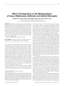
MATERIALS AND METHODS Materials Tetracalcium phosphate (TTCP, Ca4(PO4)2O) and dicalcium phosphate dihydrate (DCPD, CaHPO4 · 2H2O) were purchased from Wako Chemical Co. (Tokyo, Japan). Collagen from bovine achilles tendon, Type 1 was purchased from Sigma-Aldrich Co. (St. Louis, MO, U.S.A.) Self-Setting Apatite/Collagen Composite Cements with Continuous Holes Blocks (APN, APC and ACC) of apatite cement, apatite cement with continuous holes, and apatite/collagen composite cement with continuous holes were prepared as follows. First, a bulk powder of apatite cement (AP) consisting of an equimolar mixture of TTCP and DCPD was prepared by grinding at 20 strokes per second for 17 min in an agate vibration mixer mill (Retsch Co., Germany; 10ml volume chamber in a ball 10 mm in diameter) according to a procedure described previously.26,27) Then, a bulk powder of apatite/collagen composite cement (AC) was obtained by grinding 20% mass ratio collagen in mass ratio and the bulk powder of AP at 10 strokes per second for 5 min. The bulk powder (0.500 g) of AP or AC was mixed homogeneously with 0.200 ml of 25 mM phosphoric acid to form a paste on a glass plate for 1 min using a spatula. The final paste was poured into a cubic mold (5⫻5⫻5 mm) in which 8⫻2 stainless steel needlelike male dies were arranged, and stored and hardened at 37 °C and 100% relative humidity for 24 h. The pins and metal mold were then removed carefully to retrieve AP and AC blocks with inter connective holes (APC and ACC). The total number of holes in a block was 16 (8⫻2) as shown in Fig. 1. The APN block was obtained similarly but using a stainless steel mold without cross pins. A sintered AP (SAP) was obtained to heat-treat the AP in an electrical furnace (TMF-5T, THOMAS KAGAKU, Tokyo, Japan) at 800 °C for 1 h. Powder X-Ray Diffraction Analysis Powder X-ray diffraction (XRD) profiles of the cement samples were measured (RINT-Ultima-III, Rigaku, Co., Japan; CuKa radiation, 40 mA, 40 kV). The scanning was performed with an integration time of 1 min at intervals of 2° (2q ). The range of diffraction angles was 3—40° Animal Experiments Animal care was according to the Animal Care Committee guidelines of the Research Institute of Pharmaceutical Sciences, Faculty of Pharmacy, Musashino Table 1. Formulation of Apatite/Collagen Composite Cement with Continuous Holes Name
Cement (%)
Collagen (%)
Holes
APN APC ACC
100 100 80
0 0 20
0 16 16
Fig. 1.
Images of Implanted Blocks,(a) APN, (b) APC, and (c) ACC
University. The experiments were performed with 5 weeks old female Spragae-Dawley (SD) rats that averaged 180 g in weight (from Crea Co., Japan). The animals were maintained at room temperature with a 12—12 h light–dark cycle, given distilled water, and fed a standard diet. The animals were divided into 3 groups to be implanted with APN, APC, or ACC. The animals were given the anesthetic Nembutal (Pentobarbital) (Dainippon Sumitomo Pharma Co., Japan) (1 ml/kg), the back, was cut open and blocks of artificial bone were implanted subcutaneously. The rats were fed normal food for 13 weeks, and the implanted blocks were measured by X-ray computed tomography (CT) once a week under anesthesia as described bellow conditions. After then, the rats were killed with an overdose of Nembutal administered intraperitoneally. In-Vivo Measurements of the Density, Volume and Total Amount of Implanted Blocks by X-Ray Computed Tomography (X-Ray CT) Since the blocks were implanted in the back subcutaneously, the parameters of X-ray CT could be measured without any effects of natural bone. X-ray CT was conducted a using Latheta (LCT-100A, Aloka Co., Ltd., Tokyo, Japan): The tube target is Cu with filter Ni. The tube current was 1 mA; tube voltage was 50 kV, pixel size; 480⫻480, slice interval was 100 m m, and resolution was 60 m m. The density, the volume and inorganic content of the cement blocks were evaluated based on specific standard materials (Inorg. Mat., Aloka Co., Ltd., Tokyo, Japan) for Xray CT using X-ray CT computer software (Pythagorean theorem, Aloka Co., Ltd., Tokyo, Japan). Statistical Testing All data are the mean and standard deviation of 4—6 measurements. A repeated measures analysis of variance (ANOVA) was used to determine significant differences among groups and a p-value of 0.05 was considered significant. RESULTS XRD Profiles of APN, APC and ACC before and after Implantation in Rats Figure 2 shows the XRD profiles of APN, APC and ACC before and after implantation. The profile of SAP (Fig. 2f), a typical hydroxyapatite, showed peaks at 2q ⫽26° and 32°. The XRD profile of natural bone (Fig. 2e) showed apatite-like diffraction pattern, but its peaks were much broader than those of SAP. The profile of APC (Fig. 2a) also showed broad peaks at 2q ⫽26° and 32° similar to rat bone with lower crystallinity, but had small peaks due to TTCP at 29°. The profiles of SAP and the raw materials indicated that most of the AP was transformed into a low crystalline hydroxyapatite, but a small amount of raw material was not. In contrast, that of ACC (Fig. 2b) showed broader peaks due to hydroxyapatite and no peak due to raw materials. After being implanted for 13 weeks, APC did not show smaller peaks due to raw materials. The XRD profile of ACC was almost the same as that of natural bone. Changes of X-Ray CT Images of Implanted Blocks in Rats Figure 3a shows X-ray CT images for the entire body of a rat. The images were taken from above with the anesthetized rat restrained so as not to move on its’ back. ACC was implanted in the back. Figures 3b—d shows cross-sections of the implanted ACC (Fig. 3b), APC (Fig. 3c) and APN (Fig. 3d) in rats after 0, 4
1230
Vol. 33, No. 7
Fig. 4.
Time Courses of the Change in Volume of APC
The triangles indicate ACC, the squares indicate APC, and the rhombuses indicate APN. All data are the mean of 4-6 measurement⫾standard deviations.
Fig. 2.
XRD Profiles of Apatite/Collagen Composite Cement
(a) APC, (b) ACC, (c) APC after implantation for 13 weeks, (d) ACC after implantation for 13 weeks, (e) natural bone, (f) SAP, (g) TTCP, (h) DCPD, (i) TTCP⫹DCPD, (j) TTCP⫹DCPD⫹collagen, (k) hydroxyapatite (standard chemicals).
Fig. 5. Time Courses of the Change in the Total Amount of Hydroxyapatite in APC The triangles indicate ACC, the squares indicate APC, and the rhombuses indicate APN. All data are the mean of 4—6 measurements⫾standard deviation.
Fig. 3.
X-Ray CT Images of Cross-Sections of APCs in Rat
(a) X-Ray CT image of a rat from above. The white circle indicates ACC. (b) ACC, (c) APC, (d) APN. (1) After implantation for 0 weeks, (2) 4 weeks, and (3) 13 weeks. White arrows indicate the blocks.
and 13 weeks. The size of implanted block of ACC was significantly decreased and their shape was changed, but those of APC and APN were not significantly. The X-ray absorption intensity in the image of ACC decreased with time sig-
nificantly. In contrast, the absorption intensity of APC and APN did not decrease. Figure 4 shows the time course of the change in volume of APN, APC, and ACC in rats. The volume of ACC decreased continuously at a consistent rate from beginning to end, and that was about 50% decreased after 13 weeks. In contrast, the volume of APN and APC were less than 10% decreased, and those didn’t show major changes. Figure 5 shows the time course of the change in the inorganic content of APN, APC, and ACC in rats. The amount of inorganic material in APN was almost constant from beginning to end, while that in APC increased slightly after 13 weeks. In contrast, the inorganic content of ACC decreased continuously after implantation, with almost the same pattern as volume. That of ACC decreased about 40% after 13 weeks. Figure 6 shows the time course of the change in density of the blocks after implantation in rats. The density of APC and ACC increased with time for 6 week. Then, the density of APC rose continuously, but that of ACC decreased slightly. The density of APN remained unchanged during the first stage. After that it rose gradually similar to APC. Figure 7 shows the implantation of ACC after only 2 weeks. The photograph indicated that the soft tissue invaded the holes of ACC after 2 weeks.
July 2010
Fig. 6. Blocks
Time Courses of the Change in Density of Hydroxyapatite in the
The triangles indicate ACC, the squares indicate APC, and the rhombuses indicate APN. All data are the mean of 4—6 measurements⫾standard deviation.
Fig. 7.
Photograph of ACC after Implantation for 2 Weeks
DISCUSSION Effect of the Chemical Structure of Implanted Apatite Blocks on Bioabsorption during Implantation The chemical formulation of the AC block was almost the same as that of natural bone, i.e. 20% collagen and 80% hydroxyapatite. Kikuchi et al.28) reported that hydroxyapatite and collagen are self-organizing, and that the molecular form of nanostructure hydroxyapatite/collagen composites formed by a simultaneous titration co-precipitation method is very important to the biocompatibility of artificial bone in vivo. They concluded that the molecular interaction between apatite and collagen induced the nanostructure to form, which had biocompatibility and characteristics similar to natural bone. In our previous study,25) the XRD profile of self-setting hydroxyapatite/collagen composite cement was similar to that of natural bone, and the hardened block was bioabsorbed after being implanted in rats. APC (Fig. 2a) had broad peaks at 2q ⫽26° and 32° similar to rat bone with lower crystallinity, but had a small amount of TTCP. The result of APC indicated that the raw materials were not completely transformed into hydroxyapatite. In contrast, ACC result (Fig. 2b) indicated that it had low crystallinity hydroxyapatite without raw materials. For the reason, since collagen catalyzed the formation of apatite at 37 °C, and raw materials transformed into apatite on collagen matrices, so ACC had the lowest crystallinity hydroxyapatite
1231
the same as natural bone. After 13 weeks, APC no longer contained raw materials. This indicated that the raw materials were transformed into low crystallinity hydroxyapatite during implantation since they included meta-stable calcium phosphates. ACC had almost the same diffraction pattern as natural bone, meaning that the low crystallinity hydroxyapatite in ACC was similar to natural bone. In other words, ACC was expected to be recognized as natural bone better than the artificial bone currently used in clinical practice. Effect of Geometrical Structure on the Bio-Absorption of Implanted Apatite Blocks Determined Using X-Ray CT After implantation, the absorption in ACC (Fig. 3b) decreased with time, suggesting that the block was bioabsorbed with time. In contrast, absorption did not decrease in APC (Fig. 3c) or APN (Fig. 3d), indicating that the blocks were not bioabsorbed. The imaging analyzing software used in this study targets the inorganic material in implanted blocks, which have a low radiolucency like bone, because the major structural component of the blocks is hydroxyapatite. The volume and inorganic content of the blocks were evaluated based on X-ray CT images. The volume was almost the same as the amount of inorganic material. The volume and the amount of ACC (Figs. 4, 5) decreased continuously at a constant rate. The block would have been phagocytized immediately by bone cells, such as osteoclast cells. As described in the X-ray diffraction section, the crystalline structure of ACC was almost the same as that of collagen/hydroxyapatite composite by Kuboki et al.,17—20) and both materials consisted of an apatite/collagen composite similar to natural bone. They concluded their materials were phagocytized on the surface of macro-pores by penetrated bone-like cells the same as the remodeling of bone. Therefore, ACC also might be phagocytized on the surface of macro-pores by penetrated bone-like cells the same as the remodeling of bone. In contrast, APN and APC consisted only of the inorganic compound hydroxyapatite, and did not contain collagen, so the bioabsorption was not as rapid as that of ACC. The reason for the decrease may be that although the outer surface area was decreased by the phagocytosis, the inner surface area of holes increased. So, the total surface area of ACC was conserved. The volume of APN and APC didn’t show major changes. On the other hand, the amount of inorganic material in APC increased slightly. The surface area of APC was greater than that of APN because APC had continuous holes. Therefore, more hydroxyapatite was deposited on APC than on APN. As shown in Fig. 6, the density profiles of the implanted blocks were significantly different from the results regarding volume and inorganic content. The density of APC and APN increased continuously after 6 weeks, but the rate of increase was greater for APC since it had a larger surface area than APN. In the micro pores of APN, body fluid did not flow smoothly, so the deposition of hydroxyapatite was slow. In contrast, hydroxyapatite was deposited on the surface of APC more rapidly through the continuous holes. The density of ACC increased until around 4 weeks, and then, slightly decreased. In the block of ACC, hydroxyapatite was deposited on the surface of holes during the first stage. Then, the density was decreased by phagocytes any osteoclast-like
1232
cells. Soft tissue (Fig. 7) invaded the holes of ACC. This result was consistent with the increase in density at the initial stage. ACC might therefore have good biological affinity and be invaded by soft tissue. CONCLUSION A cell scaffold for bone regenerative medicine was developed using self-setting apatite/collagen composite cement. The cement hardened under conditions found in the human body (37 °C, 100% RH), and was transformed into low crystalline hydroxyapatite. ACC had continuous macro holes, so tissue is more likely to invade it than APN. According to the results, substitution with natural bone tends to take place in ACC. The 300—500 m m holes resulted in a higher rate of formation of vascular-like tissue. They also resulted in the activated remodeling of implanted materials. Selfsetting/low-crystallinity APC would be better than the preparations in clinical use nowadays. Acknowledgements This study was supported in part by a grant, MEXT. HAITEKU (2004—2008), from the Ministry of Education, Culture, Sports, Science and Techology, Japan. REFERENCES 1) Hirota K., Nishihara K., Tanaka H., Biomed. Mater. Eng., 3, 147—151 (1993). 2) Okazaki M., Ohmae H., Takahashi J., Kimura H., Sakuda M., Biomaterials, 11, 568—572 (1990). 3) Zardiackas L. D., Teasdall R. D., Black R. J., Jones G. S., St. John K., Dillon L. D., Hughes J. L., J. Appl. Biomater., 5, 277—283 (1994). 4) Asahina I., Watanabe M., Sakurai N., Mori M., Enomoto S., J. Med. Dent. Sci., 44, 63—70 (1997). 5) TenHuisen K. S., Martin R. I., Klimkiewicz M., Brown P. W., J. Biomed. Mater. Res., 29, 803—810 (1995). 6) John A., Hong L., Ikada Y., Tabata Y., J. Biomater. Sci. Polym. Ed., 12, 689—705 (2001). 7) Mehlisch D. R., Leider A. S., Roberts W. E., Oral Surg. Oral Med. Oral Pathol., 70, 658—692 (1990).
Vol. 33, No. 7 8) Martins V. C. A., Goissis G., Ribeiro A. C., Marcantônio E. Jr., Bet M. R., Artif. Organs, 22, 215—221 (1998). 9) Tampieri A., Celotti G., Landi E., Sandri M., Roveri N., Falini G., J. Biomed. Mater. Res. A, 67, 618—625 (2003). 10) Kikuchi M., Itoh S., Ichinose S., Shinomiya K., Tanaka J., Biomaterials, 22, 1705—1711 (2001). 11) Itoh S., Kikuchi M., Takakuda K., Koyama Y., Matsumoto H., Ichinose S., Tanaka J., Kawauchi T., Shinomiya K., J. Biomed. Mater. Res., 54, 445—453 (2001). 12) Kikuchi M., Taguchi T., Matsumoto H., Tanaka J., Takakuda K., KeyEngineering Materials, 2002, 218—220, 449—452 (2002). 13) Itoh S., Kikuchi M., Koyama Y., Takakuda K., Shinomiya K., Tanaka J., Biomaterials, 23, 3919—3926 (2002). 14) Kuboki Y., Saito T., Murata M., Takita H., Mizuno M., Inoue M., Nagai N., Poole A. R., Connect. Tissue Res., 32, 219—226 (1995). 15) Kuboki Y., Takita H., Kobayashi D., Tsuruga E., Inoue M., Murata M., Nagai N., Dohi Y., Ohgushi H., J. Biomed. Mater. Res., 39, 190—199 (1998). 16) Tsuruga E., Takita H., Itoh H., Wakisaka Y., Kuboki Y., J. Biochem., 121, 317—324 (1997). 17) Kuboki Y., Jin Q., Takita H., J. Bone and Joint Surgery (American), 83, S105—S115 (2001). 18) Kuboki Y., Takita H., Mizuno M., Fujisawa R., Dentistry Japan, 37, 42—50 (2001). 19) Jin Q. M., Takita H., Kohgo T., Atsumi K., Itoh H., Kuboki Y., J. Biomed. Mater. Res., 51, 491—499 (2000). 20) Kuboki Y., Jin Q., Kikuchi M., Mamood J., Takita H., Connect. Tissue Res., 43, 529—534 (2002). 21) Otsuka M., Matsuda Y., Suwa Y., Fox J. L., Higuchi W. I., J. Pharm. Sci., 83, 259—263 (1994). 22) Otsuka M., Nakahigashi Y., Matsuda Y., Fox J. L., Higuchi W. I., J. Pharm. Sci., 83, 1569—1573 (1994). 23) Otsuka M., Nakahigashi Y., Matsuda Y., Fox J. L., Higuchi W. I., Sugiyama Y., J. Controlled Release, 43, 115—122 (1997). 24) Otsuka M., Yoneoka K., Matsuda Y., Fox J. L., Higuchi W. I., Sugiyama Y., J. Pharm. Pharmacol., 49, 1182—1188 (1997). 25) Otsuka M., Matsuda Y., Suwa Y., Fox J. L., Higuchi W. I., J. Pharm. Sci., 83, 611—615 (1994). 26) Otsuka M., Kuninaga T., Otsuka K., Higuchi W. I., J. Biomed. Mater. Res. B, Appl. Biomat., 79B, 176—184 (2006). 27) Brown W. E., Chow L. C., “Cement Research Progress,” ed. by Brown P. W., American Ceramic Society, Westerville, Ohio, 1986, pp. 352— 379. 28) Kikuchi M., Itoh S., Ichinose S., Shinomiya K., Tanaka J., Biomaterials, 22, 1705—1711 (2001).