Proceedings of the 2nd Thermal and Fluid Engineering Conference, TFEC2017 4th International Workshop on Heat Transfer, IWHT2017 April 2-5, 2017, Las Vegas, Nevada, USA
TFEC-IWHT2017-18648
EFFECT OF HYDRODYNAMIC BOUNDARY LAYER STRUCTURE ON THE PERFORMANCE OF A SWIRL FLOW MICROCHANNEL HEAT SINK FOR HIGH HEAT FLUX APPLICATIONS ˜ 1 Benjamin Herrmann-Priesnitz1,∗ & Williams Calder´on-Munoz 1 Department
of Mechanical Engineering, Universidad de Chile, Beauchef 851, Santiago, Chile
ABSTRACT Numerical simulations of velocity and temperature fields to study the performance of a single phase microchannel cooling system with spiraling radial inflow for high heat flux applications are presented. Skin friction coefficient and Nusselt number are calculated for different microchannel heights and flow inlet angles. As the fluid moves radially inward, entraining boundary layers develop due to a rotation induced crossflow. Entrainment effects are found to enhance convective heat transfer considerably due to motion of fluid towards the heat exchange surface. The strength of this effect depends on the structure of hydrodynamic boundary layers, which is characterized by the Reynolds number and the flow inlet angle. In this work it is found that boundary layers may merge and the entrainment effect is lost when reducing the microchannel height, therefore the total heat flux may not always increase with a decrease of the flow passage area, as opposed to conventional microchannels. The swirl flow microchannel heat sink showed promising cooling characteristics for applications such as thermal management of electronics or concentrated photovoltaics.
KEY WORDS: Laminar flow, boundary layer, convective heat transfer, swirl flow heat sink.
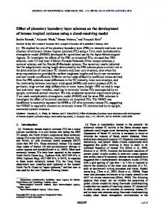
1. INTRODUCTION High heat flux removal is required in numerous industrial applications, such as electronics cooling and concentrated photovoltaics [1]. Thermal management is important for the performance, safety, and lifetime of these devices [2, 3], which is why high heat flux cooling technologies is one of the most active fields of heat transfer research today. Most promising solutions using single phase liquid cooled heat sinks include designs with jet impingement, flow through porous media, and microchannels [4]. A novel swirl flow microchannel heat sink was designed and studied by Ruiz and Carey [5, 6]. The authors showed that the design is promising, a heat flux of 113 W/cm2 was achieved using water as the working fluid, while maintaining a surface temperature below 80 o C and a ratio of pumping power to heat rate of 0.03% [5, 6]. The device consists on an annular cavity where fluid is admitted through the external radius, spirals radially inward and exits through the internal radius, heat is removed from one of the cavity walls whereas the other is insulated. A schematic of the heat sink design is shown in Fig. 1. Thermal design exploration of this device was carried out by Herrmann-Priesnitz et al. [7]. The structure of hydrodynamic boundary layers was investigated and the influence of a Reynolds number and the flow inlet angle over the flow patterns was analyzed. Rotation of the fluid induces a crossflow and entrainment, which was found to enhance convective heat transfer considerably due to motion of fluid towards the heat exchange surface. This effect, as well as the pressure drop on the
∗
Corresponding Benjamin Herrmann-Priesnitz:
[email protected] 1
TFEC-IWHT2017-18648
(b)
(a)
Fig. 1 Schematic of a swirl flow microchannel heat sink. (a) Top view. (b) Cross-sectional view. channel depend on the structure of hydrodynamic boundary layers. This is further investigated in the present article by calculating the average skin friction coefficient and average Nusselt number for different channel heights, h, and flow inlet angles, β.
2. METHODOLOGY The swirl flow microchannel heat sink is modelled as an annular cavity with imposed radial inflow. The cavity has a height h, an outer radius ro where the fluid enters with an inlet angle β, and an inner radius ri where the flow exits. Mass, momentum, and energy balances for the fluid are governed by continuity, Navier-Stokes and thermal energy equations respectively. The fluid is considered to be incompressible, with constant physical properties, the flow is in steady-state and has axisymmetry, and buoyant effects as well as viscous dissipation are neglected. In the resulting equations, the velocity field is uncoupled from the temperature field. For a cavity with small aspect ratio h2 /ro ≪ 1, the boundary layer approximation form of equations can be used [7, 8]. Therefore, the original elliptic partial differential equation (PDE) problem reduces to parabolic PDE problem. Velocity field is calculated using the integral method developed by Herrmann-Priesnitz et al. to solve rotating boundary layer flows inside annular cavities [8]. Temperature field is calculated using a time marching technique until steady-state is reached. Chebyshev spectral collocation is used to calculate derivatives in the axial direction z, a second-order upwind scheme is used to differentiate in the radial direction r, and an explicit Euler method is used for the time derivative, as presented in Ref. [7]. Velocity and temperature fields are computed for a swirl flow microchannel heat sink with an external radius ro = 1 cm, an inner radius ri = 0.15 cm, water inlet temperature of 25 o C, a fixed flow rate of 300 ml/min, ′′ = 30 W/cm2 on the other wall. Flow inlet zero heat flux on the insulated wall, and a constant wall heat flux qw angle and channel height are varied to study the effect of boundary layer structure on the heat sink performance parameters.
3. RESULTS & DISCUSSION 3.1 Streamlines and temperature contours Streamlines in the r–z plane, as well as boundary layer structures and temperature contours for the combinations β = 4o with h = 800 µm and β = 8o with h = 200 µm, are shown in Fig. 2. The flow enters the channel with a uniform velocity profile, as it moves radially inward boundary layers start to grow, and at the same
2
TFEC-IWHT2017-18648
(a) β = 4o and h = 800µm.
(b) β = 10o and h = 200µm.
Fig. 2 Streamlines in the r–z plane and temperature contours. time fluid is drawn towards the walls due to rotation effects. Competition between these effects determines if boundary layers merge, as shown in Fig. 2(a), or entraining boundary layers develop, as shown in Fig. 2(b).
3.2 Friction factor and Nusselt number The Darcy friction factor is calculated as follows f=
dh ∆p , L ρu2 /2
(1)
where ρ is the density of the fluid, dh = 2h is the hydraulic diameter, u is the average radial flow velocity, ∆p is the total pressure drop, and L is the length of flow along the spiral pathline within the device. The friction factor is usually scaled with the Reynolds number based on the hydraulic diameter Re = udh /ν, where ν is the kinematic viscosity of the fluid. For fully developed laminar flow between parallel plates we have f Re = 96. The average Nusselt number is calculated as follows 1 Nu = (ro − ri )
Z
ro ri
′′ d qw h dr, (Tw − Tb )λ
(2)
where Tw is the temperature at the wall, Tb is the z–averaged temperature, and λ is the thermal conductivity of the fluid. For fully developed laminar flow between parallel plates where one wall is insulated and the other has a constant heat flux we have Nu = 5.39. Scaled friction factor and average Nusselt number are calculated for the swirl flow microchannel heat sink using different values of h and β, as shown in Fig. 3. First, the flow inlet angle is kept constant at β = 10o , and h is varied from 100–400 µm where boundary layers merge, and from 600–1000 µm where entraining boundary layers develop. Then β is varied between 4o –64o and the channel height is fixed at 200 µm, where boundary layers merge, and at 800 µm where entraining boundary layers develop. The dashed lines in Figs. 3(a) and (b) correspond to the values for fully developed flow between parallel plates. Results for both, f and Nu, approach the dashed line when boundary layers are merged, and get closer for decreasing values of h and increasing values of β (90o is fully radial flow). Friction factor and Nusselt number are higher when entrainment is present, therefore convective heat transfer is enhanced, with an additional pumping cost.
4. CONCLUSIONS Numerical simulations of velocity and temperature fields in a swirl flow microchannel heat sink were carried out to study the effect of hydrodynamic boundary layer structure on the device performance parameters. In
3
TFEC-IWHT2017-18648
(a) Scaled friction factor.
(b) Average Nusselt number.
Fig. 3 Heat sink performance parameters as a function of channel height flow inlet angle. particular, the friction factor and Nusselt number were calculated for different microchannel heights and flow inlet angles. Merged boundary layers were found for h ≤ 400 µm and entraining boundary layers were observed for h ≥ 600 µm. An increase in friction factor and Nusselt number was observed when entrainment was present, which is explained due to the movement of fluid towards the walls.
ACKNOWLEDGMENTS B. H-P. thanks CONICYT- Chile for his Ph.D. scholarship CONICYT-PCHA/Doctorado Nacional/2015-21150139.
REFERENCES [1] A. Royne, C. Dey, and D. Mills, “Cooling of photovoltaic cells under concentrated illumination: a critical review,” Solar Energy Materials and Solar Cells, vol. 86, no. 4, pp. 451–483, 2005. [2] J. Osses-M´arquez and W. R. Calder´on-Mu˜noz, “Thermal influence on charge carrier transport in solar cells based on GaAs PN junctions,” J. Appl. Phys., vol. 116, no. 15, p. 154502, 2014. [3] W. R. Calder´on-Mu˜noz and C. Jara-Bravo, “Hydrodynamic modeling of hot-carrier effects in a PN junction solar cell,” Acta Mechanica, pp. 1–14, 2016. [4] B. Agostini, M. Fabbri, J. E. Park, L. Wojtan, J. R. Thome, and B. Michel, “State of the Art of High Heat Flux Cooling Technologies,” Heat Transfer Engineering, vol. 28, no. 4, pp. 258–281, 2007. [5] M. Ruiz and V. P. Carey, “Prediction of Single Phase Heat and Momentum Transport in a Spiraling Radial Inflow Microchannel Heat Sink,” No. HT2012-58328, ASME, Jul 2012. [6] M. Ruiz and V. P. Carey, “Experimental Study of Single Phase Heat Transfer and Pressure Loss in a Spiraling Radial Inflow Microchannel Heat Sink,” Journal of Heat Transfer, vol. 137, no. 7, p. 071702, 2015. [7] B. Herrmann-Priesnitz, W. R. Calder´on-Mu˜noz, A. Valencia, and R. Soto, “Thermal design exploration of a swirl flow microchannel heat sink for high heat flux applications based on numerical simulations,” Applied Thermal Engineering, vol. 109, pp. 22–34, 2016. [8] B. Herrmann-Priesnitz, W. R. Calder´on-Mu˜noz, E. A. Salas, A. Vargas-Uscategui, M. A. Duarte-Mermoud, and D. A. Torres, “Hydrodynamic structure of the boundary layers in a rotating cylindrical cavity with radial inflow,” Physics of Fluids, vol. 28, no. 3, p. 033601, 2016.
4