Fault rupture propagation through soils has received much attention over the past two decades. However, ..... Abaqus V.6.10 user's manual. ... and implications for design, Soil Dynamics and Earthquake Engineering 27,938â956. Lazarte, C.A. ...
Effect of Mechanical Soil Parameters on Fault Rupture Propagation through Granular Soils M. Mortazavi Zanjani, A. Soroush & R. Solhmirzaei Amirkabir University of Technology, Tehran, Iran
SUMMARY: Fault rupture propagation through soils has received much attention over the past two decades. However, investigating the effect of local site conditions and soil types on fault rupture path requires a detailed study. In this paper numerical modeling of fault rupture propagation in a horizontal soil layer from base rock to the surface is performed using non-linear Finite Element Method. The results have been verified with 1g and centrifuge physical simulations and the dependency of results on mesh density and alignment is studied. Mechanical soil parameters are assumed to vary in a physically acceptable range; and Elastic Modulus, friction and dilation angles are shown to have significant impact on rupture path in granular materials. The effects of Poisson’s Ratio, coefficient of lateral earth pressure and scaling due to confinement are also studied. Keywords: Fault rupture, FEM, granular soil, parametric study
1. INTRODUCTION The phenomenon of fault rupture propagation through soil layers has been the subject of many numerical analyses as well as physical modeling and field studies. Field studies have focused on evidences from surface observations and trenches (Bray et al., 1990; Bonilla and Lienkaemper, 1990). Along these findings, other researchers tried to model soil layer behavior in laboratory tests, (Cole and Lade, 1984; Bray et al., 1990; Lazarte, 1996; Johansson and Konagai, 2006; Lin et al., 2006) and in numerical simulations (Bray et al., 1994; Lazarte, 1996; Johansson and Konagai, 2007; Lin et al., 2006; Anastasopoulos et al., 2007; Loukidis et al., 2009). Through these efforts, many aspects of fault rupture propagation have been established. However, the effect of different soil parameters on rupture needs more investigations. In this paper, numerical modeling is employed and verified through physical modeling, while robustness of the results is checked by utilizing different mesh sizes and structures. To estimate the effect of soil characteristics on fault rupture pattern, a benchmark problem is set and the target parameters are changed in an acceptable range. Thus, the individual effect of each parameter is investigated. Moreover, the scaling of Elastic Modulus is proposed for different soil layer thicknesses.
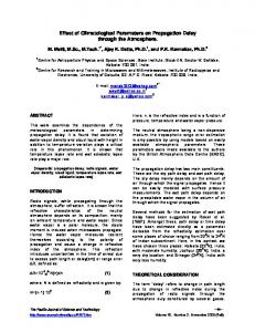
2. PROBLEM DESCRIPTION AND NUMERICAL METHOD A horizontal homogeneous dry soil layer of thickness H is subjected to dip-slip reverse fault. For the simulation of fault movement, the right side of the layer is assumed to be fixed and an upward movement with angle of is applied to the left side. Fig. 1.1. shows the typical geometry and boundary conditions of the model. The numerical analysis is static and plane strain conditions are assumed to govern the geometry and loading of the model.
B=5H
H
Figure 1.1. Soil model and boundary conditions
2.1. Numerical Analysis Numerical analyses are performed using the Finite Element Code Abaqus (Abaqus, 2010). For the numerical simulation of a 10 meter high soil deposit, a rectangular area of 10m×50m is modeled with 40×121 elements. The elements are finer (0.25×0.25m) in the 2H-width middle part of the model and coarser (1.67×0.25m) in the sides. An elasto-plastic constitutive model with non-associated flow rule is assigned to the model. The yield surface is Mohr-Coulomb yield surface whereas the flow potential is in the form of Menetrey and Willam functions. A benchmark soil type is considered with parameters shown in Tab. 1.1. Then each parameter is changed separately in the variation range introduced in the table to trace the consequent results. According to the literature, a vertical base displacement of 2-6 percent of the height of the layer is needed for the rupture to reach the surface. Herein, a vertical base displacement of 4 percent of the height of the layer (i.e. 40cm) is employed. The dip angle (the angle of fault direction with horizon) is assumed 30, 45, 60 and 75 . Table 1.1. Soil parameters used in numerical simulation
c (kPa)
0.38
0.3
5
0.31~0.47
0.27~0.35
-
Material
(kN m3 )
E (MPa)
()
()
K0
benchmark
20
20
38
8
Variation range
-
10~30
32~44
2~14
unit weight
E Elastic Modulus
c
friction angle dilation angle
E coefficient of lateral earth pressure
Poisson’s Ratio
cohesion
2.2. Mesh Dependency Localized strains and shear band formation are the inherent aspects of fault rupture propagation. Within shear band, very sharp strain gradients, noticeable volume changes and grain rotations can be observed (Oda and Kazama, 1998). Numerical modeling is expected to capture narrow shear bands. During recent years, different approaches such as embedded strong discontinuity approaches ( Borja, 2002) and micro-polar continuum approaches ( De Borst, 1991). Having been developed for exact modeling of shear bands, these methods have produced impressive results in experimental scales but the limiting mesh size, 3-5 times the mean particle size to obtain mesh independent results, pose a barrier to applying them to practical problems.
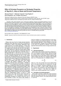
Regarding the engineering need for simulating different cases, a simpler approach, Finite Element method, is employed. However, for the assurance of realistic description of rupture, mesh independency was checked from mesh density and mesh structure point of view. Four different mesh sizes, 75, 50, 25 and 20 cm, were analyzed and narrower shear band was generated in finer mesh, as expected. However, by tracing results from coarse mesh to fine mesh it was seen that the central line is gradually approaching a single line and shows convergence. The effect of mesh structure on rupture was studied by two structured and unstructured 25 cm meshes and almost similar rupture paths were observed. 2.3. Verification The results of numerical analyses are compared to two groups of existing experiments: 1g fault rupture propagation experiments by Cole and Lade (Cole and Lade, 1984) and centrifuge experiments by Anastasopoulos et al. (Anastasopoulos et al, 2007). The testing apparatus of Cole and Lade consisted of a 142 cm long, 56 cm high and 15 cm wide glass-walled one half of which was moveable along various angles. The friction angle for sand was 58° and the angle of dilation was measured 30°. The average dry density of the sand was 1.627 gr cm3 . Fig. 2.1. compares the results of numerical analysis with those of the physical modeling; good agreements, except for the fault with 45° dip angle, are obvious. Centrifuge tests of Anastasopoulos et al. were conducted at 100g centrifugal acceleration for a 60° reverse fault. The length, height and width of soil specimen were 68, 25 and 20 cm, respectively which would represent a 68×25×20m sample considering the centrifuge acceleration. For the numerical predictions they suggested the following parameters: 39, 11 . Elastic Modulus, E 13.65MPa , was determined from the direct shear tests conducted by Anastasopoulos et al. (2007).
Figure 2.1. Numerical results of reverse fault rupture propagation of this study through dense sand in different fault dip angles in comparison with experimental results of Cole and Lade
Vertical displacement (m)
d=0
1.2 1.0
Experiment Analysis h=1.13 m h=0.70 m h=0.49 m h=0.18 m
0.8 0.6 0.4 0.2 0 -30
-20
-10
0
10
20
Horizontal distance d(m)
Figure 2.2. Reverse faulting at 60° with h=0.2 to 1.2 m, imposed bedrock dislocation: comparison of vertical displacement of the surface in numerical simulation of this study with experimental results of Anastasopoulos et al.
Although, there is a slight difference in the tail of surface outcropping (left side of figure) at the downthrown block, the overall prediction of the surface settlement profile remains satisfactory.
3. RESULTS To study the effect of soil parameters on rupture path, contours of maximum strains are used for comparison (Fig. 3.1.(a)). Moreover, for an easier comparison, the line passing through the peak points of each contour interval, hereafter called the central line, is illustrated, as Fig 3.2.(a). 3.1. Elastic Modulus Fig 3.2.(a) Shows the results for 60° reverse fault rupture propagation for three different Elastic Modulus values; the other parameters were kept constant. Central lines of three rupture paths are depicted together in a diagram for comparison. It is clear from the results that for larger values of Elastic Modulus the rupture path is less steep. Similar results are found for the other fault dip angles. 3.2. Friction and Dilation Angle The effect of friction angle and dilation angle are studied simultaneously, as generally any variation in friction angle is accompanied by a variation in dilation angle and here the value of is related to by the relation 30 . Fig 3.1.(b) and Fig 3.2.(b) represent the analysis results for 60° reverse fault where 38, 38 6 , while other parameters are the same as the benchmark problem. The increase in generates less steep rupture paths which is observed in other fault dip angles.
(a)
The effect of Elastic Modulus E
(b)
The effect of friction angle
Figure 3.1. The effects of Elastic Modulus and friction angle on rupture paths: Contours of maximum strains for 60° reverse fault in 4% vertical base displacement (a) E 10,20,30 MPa, 38 , c 5 kPa , 0.3 ,
K0 0.38 (b) 32, 38, 44 , E 20 MPa , c 5 kPa , 0.3 , K0 0.38
(a) The effect of Elastic Modulus E
(a) The effect of friction angle
Figure 3.2. The effect of Elastic Modulus and friction angle on rupture paths: Central lines of contours for 60° reverse fault in 4% vertical base displacement. (a) E 10,20,30 MPa, 38 , c 5 kPa , 0.3 ,
K0 0.38 (b) 32, 38, 44 , E 20 MPa , c 5 kPa , 0.3 , K0 0.38
3.3. Lateral Earth Pressure Coefficient The coefficient of lateral earth pressure is derived from the relation K0 1 sin and its variation for each case is calculated considering 6 . Fig. 3.3. demonstrates rupture paths in two different fault dip angles and for two different soil types. This figure and other analyses show that variation of K 0
mainly influence the results in smaller fault dip angles. It can be said that in larger dip angles rupture path is more vertical and, consequently, not much affected by lateral soil conditions.
\
38
46
60
30
Figure 3.3. The effect of coefficient of lateral earth pressure on rupture paths: central lines of contours for 30° and 60° reverse faults with 38° and 46° friction angles in 4% vertical base displacement and E 20 MPa ,
c 5 kPa , 0.3 .
3.4. Poisson’s Ratio The slight effect of Poisson’s ratio on rupture path for 60° reverse fault is depicted in Fig. 3.4. Similar results are found in other dip angles.
Figure 3.4. The effect of Poisson’s ratio on rupture paths for 60° reverse fault in 4% vertical base displacement. E 20 MPa , 38 , c 5 kPa , 0.27,0.3,0.35 , K0 0.38
4. EFFECT OF CONFINEMENT In numerical simulation of small-scale physical tests of Cole and Lade, Elastic Modulus should be selected. Regarding the high friction angle, the granular material seems to be dense and E 20 MPa is assumed. Fig 4.1. compares the rupture paths of a 60° reverse fault from Cole and Lade with the numerical simulation based on E 20 MPa . Further analyses show that smaller values of E , for instance E 5 MPa, generate better results. This finding is more investigated from a theoretical point of view. In modeling different soil layer thicknesses, the effect of problem size on confining pressure is to be considered. The values of Elastic Modulus attained in a specific confining pressure, for example for a 10 meter soil layer, needs some
modification before being applied to other models. Considering the hyperbolic constitutive model (Duncan and Chang, 1970) which accounts for confinement effects on soil behavior, the initial Elastic Modulus, Ei , is defined as:
Ei K.Pa (
3 Pa
)n
(3.1)
K is a modulus number, Pa is atmospheric pressure, n is the exponent determining the rate of variation of Ei with 3 , and 3 is the minor principal stress: Where
3 K0 gH
(3.2)
Where is density and H is soil layer thickness. Supposing equal K , Pa, n for the same atmospheric pressure conditions and for a specific soil with two different thicknesses H1,H2 :
(Ei )1 ( 3 )1n (H1)n (Ei )2 ( 3 )2n (H2 )n
(3.3)
According to Duncan and Chang, for uniform fine silica sand n is 0.54 ~ 0.65 where the lower limit is for dense sand and the upper limit is for loose sand. Then two models with 56cm and 10meter height are compared as follows:
(Ei )0.56m (0.056)0.54 0.21 (Ei )10m (Ei )0.56m 4.2MPa
(3.4) (3.5)
Thus, E 4 ~ 5 MPa would be an acceptable range for a 56cm dense sand model.
Figure 4.1. Comparison of the results of numerical modeling by different Elastic Modulus with physical test results of Cole and Lade.
5. CONCLUSION
In this study, the effect of different soil parameters on fault rupture path is studied. Elastic Modulus and friction and dilation angles are shown to have significant role on fault rupture
path. Increase in Elastic Modulus and friction angle both define denser sand which cause the fault rupture path to be less steep. Coefficient of lateral earth pressure, as the indicator of lateral stress conditions in soil, is shown to affect rupture path mostly in smaller fault dip angles. The effect of Poisson’s ratio is also studied. While modeling different soil layer thicknesses, scaling of Elastic Modulus is found to be necessary regarding confinement effect which has been explained through theoretical aspects of soil mechanics. Through these analyses, it is tried to gain more insights into the role of different parameters in fault rupture propagation of granular soils. REFRENCES Abaqus, Inc. (2010). Abaqus V.6.10 user’s manual. Anastasopoulos, I., Gazetas, G., Bransby, M.F., Davies, M.C.R. and Nahas, A.El. (2007). Fault Rupture Propagation through Sand: Finite-Element Analysis and Validation through Centrifuge Experiments. Journal of Geotechnical and Geoenvironmental Engineering 133:8,943-958. Bonilla, M. G. and Lienkaemper, J. J. (1990). Visibility of fault strands in exploratory trenches and timing of rupture events. Geology 18, 153-156. Borja RI. (2002). Finite element simulation of strain localization with large deformation: capturing strong discontinuity using a Petrov-Galerkin multiscale formulation. Computer Methods in Applied Mechanics and Engineering 191,2949-2978. Bray, J.D., Seed, R.B. and Seed, H.B. (1990) The effect of tectonic movements on stresses and deformations in earth embankments. Earthquake Engineering Research Center, University of California at Berkeley, Report No. UCB/EERC-90/13.
Bray, J.D., Seed, R.B. and Seed, H.B. (1994). Analysis of earthquake fault rupture propagation through cohesive soil. Journal of Geotechnical Engineering Division, ASCE 120:3,562-580. Cole, D. A. Jr. and Lade, P. V. (1984). Influence zones in alluvium over dip-slip Faults. Journal of Geotechnical Engineering Division, ASCE 110:5,599-615. De Borst R. (1991). Simulation of strain localization: A reappraisal of the Cosserat continuum. Engineering Computations 8,317-332. Duncan, J.M. and Chang, C.Y. (1970). Nonlinear analysis of stress and strain in soil. Journal of Soil Mechanics and Foundations Division, ASCE 96,1629-1653. Johansson, J. and Konagai, K. (2006). Fault induced permanent ground deformations—an experimental comparison of wet and dry soil and implications for buried structure. Soil Dynamics and Earthquake Engineering 26,45–53. Johansson, J. and Konagai, K. (2007). Fault induced permanent ground deformations: Experimental verification of wet and dry soil, numerical findings’ relation to field observations of tunnel damage and implications for design, Soil Dynamics and Earthquake Engineering 27,938–956. Lazarte, C.A. (1996). The response of Earth structures to surface fault rupture, Ph.D. Thesis, Department of Civil Engineering, Univ. of California, Berkeley. Lin, M.L., Chung, C.F. and Jeng, F.S. (2006). Deformation of overburden soil induced by thrust fault slip. Engineering Geology 88,70–89. Loukidis, D., Bouckovalas, G.D and Papadimitriou, A.G. (2009). Analysis of fault rupture propagation through uniform soil cover. Soil Dynamics and Earthquake Engineering 29,1389-1404. Oda, M. and Kazama, H. (1998). Microstructure of shear bands and its relation to the mechanics of dilatancy and failure of dense granular soils. Géotechnique 48,465–481.