INTERNATIONAL JOURNAL OF WIRELESS AND MOBILE COMPUTING. 1. Effective ... Computer Science Department of the University of Illinois at Urbana-. Champaign ...... group. Tree repair is carried out when a tree edge is bro- ken.
INTERNATIONAL JOURNAL OF WIRELESS AND MOBILE COMPUTING
1
Effective Location-Guided Overlay Multicast in Mobile Ad Hoc Networks Kai Chen, Member, IEEE, Klara Nahrstedt, Member, IEEE,
Abstract— Group communication has become increasingly important in mobile ad hoc networks (MANET). Current multicast routing protocols in MANET have been shown to incur large overhead due to dynamic network topology. To overcome this problem, there is a trend towards stateless multicast. For example, DDM [1] queries the underlying unicast routing protocol to forward data packets towards members of a multicast group without keeping the multicast session state information. In this paper, we introduce another stateless multicast scheme based on packet encapsulation. Multicast packets are forwarded among the group nodes via unicast routing in an overlay fashion. To construct the overlay multicast tree, we propose several novel tree construction algorithms with the goal of minimizing the overall bandwidth cost of the tree. These algorithms include: location-guided k-ary (LGK) tree, location-guided directional (LGD) tree, and location-guided Steiner (LGS) tree. All of them rely on the geometric locations of the group nodes as heuristics to compute the tree. To augment and enhance our locationguided tree construction algorithms, we propose several companion mechanisms, including location update, address compression and route caching. Our simulation results confirm that location-guided heuristics is very effective in constructing low-cost overlay multicast trees in a MANET. When location information is up-to-date, the bandwidth cost of a LGS tree is similar to that of an optimal router-assisted Steiner multicast tree. We also discover the inherent trade-off among the proposed algorithms. Our study in this paper strongly suggests that using the Location-Guided Tree (LGT) construction algorithms, overlay multicast is an effective, efficient and practical solution for group communication in MANET. Index Terms— Group communication, overlay multicast, multicast tree, location-guided multicast, Steiner tree, mobile ad hoc networks.
I. I NTRODUCTION
Kai Chen is currently with Google Inc. at Mountain View, California, U.S.A. This work has been done while he was at the Computer Science Department of the University of Illinois at UrbanaChampaign (U.S.A.). Klara Nahrstedt is currently with the Computer Science Department of the University of Illinois at UrbanaChampaign (U.S.A.).
M
OBILE ad hoc network (MANET) consists of many mobile hosts connected by wireless links. Each node operates not only as an end-system, but also as a router to forward packets. The network topology of MANET may change frequently due to the nodes’ movements. A good routing protocol should always forward packets along or close to the shortest path from source to destination, and be able to adapt quickly to topology changes. A number of unicast routing protocols have been proposed for this environment [2]. Group communication has become increasingly important in MANET due to the need for collaborative tasks among a group of mobile users. Most of the current multicast routing protocols in MANET follow the same multicast group model as in the Internet. In this model, all the routers in the network collectively maintain the multicast session state information. When a multicast packet arrives at a router, the router looks up its multicast routing table and decides to which interface(s) to forward the packet. The multicast state information changes when there is a change in the network topology or group membership. In MANET, frequent topology change and dynamic group membership often lead to substantial signaling overheads in maintaining the global multicast session state information [3]. This problem becomes worse when there is a large number of multicast groups in the network. To overcome this problem, there is a recent trend towards stateless multicast in MANET, e.g., DDM [1]. In DDM, the multicast membership is controlled by the data sources (senders). When a sender sends out a data packet, it includes a list of destination addresses in the packet. When the packet arrives at an intermediate node, DDM queries the underlying unicast routing protocol, and decides which next-hop node(s) to forward the packet towards its destinations. Therefore, it avoids the overhead of maintaining the multicast session state information at the routers, and hence is more scalable to the number of multicast groups in the network. However, DDM is only suitable for small group (few-to-few) communication because it needs to include the list of destination address in each data packet. Moreover, it requires every node in the network to cooperate in multicast routing. This may
INTERNATIONAL JOURNAL OF WIRELESS AND MOBILE COMPUTING
not be practical since a MANET is formed by a random group of users. In this paper, we introduce another stateless multicast scheme based on packet encapsulation. Multicast data is encapsulated in a unicast envelop and transmitted among the group nodes. In other words, our scheme builds an overlay multicast packet distribution tree among the group nodes, with the goal of minimizing the overall bandwidth cost of the tree. Similar to DDM, a list of destination addresses is explicitly included in each packet. The overlay multicast structure requires cooperation only from the group nodes, and hence is highly deployable. Moreover, as we will see later, our overlay multicast scheme is able to achieve very low bandwidth cost similar to that of a router-assisted multicast approach. Therefore, it retains the benefits of both sides. The focus of this paper is on the tree construction algorithms. In [4], we have proposed the location-guided k-ary (LGK) and location-guided Steiner (LGS) tree algorithms. In this paper, we propose another algorithm called location-guided directional (LGD) tree. All these algorithms rely on the geometric locations of the group nodes as heuristics to construct the overlay multicast tree. They differ in how sophisticated the location information is utilized. By using only the locations of the group nodes, there is no need to acquire the global network topology information, which is very difficult to obtain in a dynamic MANET. In our scheme, each node constructs its out-going branches to the next-level sub-trees and forwards the data packet to the root of each subtree. This process repeats until all the destinations are reached. Our simulation results confirm that locationguided heuristics is very effective in constructing a lowcost overlay multicast tree. To augment and enhance the design of our LocationGuided Tree (LGT) construction algorithms, we introduce three companion mechanisms: 1) a hybrid location/membership update mechanism to disseminate location and membership information among the group nodes; 2) an address compression mechanism to reduce the space overhead of storing the list of destination addresses in each data packet; and 3) a route caching mechanism to reduce the per-packet computational overhead by caching previously computed trees. Our contributions in this paper include: 1) design, analysis and comparison of LGK, LGD and LGS algorithms for overlay multicast in a MANET; 2) demonstrate the effectiveness of location-guided heuristics based on a study of the relation between geometric distance and network distance in a MANET; and 3) suggest overlay multicast as an effective, efficient and practical solution for group communication in a MANET. Com-
2
pared to our earlier paper [4], this paper extends the set of location-guided algorithms, and discovers a new algorithm (LGD) which performs better when location information is not accurate. This paper also proposes an address compression mechanism (Section IV-B) to reduce the address space overhead in each packet. Therefore, our scheme is suitable for not only small multicast groups, but also medium size groups. This paper is organized as follows. Section II states the overall problem and studies the relation between geometric distance and network distance. Section III describes in detail the proposed LGK, LGD and LGS algorithms. Section IV discusses the companion mechanisms to enhance our scheme. Section V gives an analytical comparison of the proposed algorithms. Section VI shows the simulation results. Section VII discusses some related work. Section VIII concludes the paper. II. P ROBLEM
AND
A SSUMPTIONS
In this section, we explain the overall problem of overlay multicast and study the relationship between geometric distance and network distance in a MANET. A. Overall Problem
�������� �
�
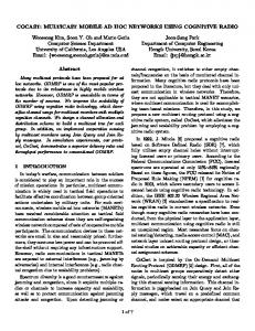
We represent the topology of a mobile ad hoc network , where is as a dynamic un-directed graph the set of mobile nodes in the network and is the set of wireless links between neighboring nodes. A subset of the network nodes in forms a multicast group. Those nodes are called group nodes, denoted by . Between the group nodes, unicast routing is available as part of the underlying unicast network routing protocol, which forms a set of paths between any two of the group nodes. The overlay virtual network is thus denoted by a un-directed complete graph . Our goal is to construct a packet distribution tree rooted at each sender node (i.e. per-source tree) in the overlay network , which spans over all members of the multicast group (Figure 1). The packet distribution tree needs to have low bandwidth cost, measured by the number of network level hops. The group nodes do not have global knowledge of the network topology . Instead, they are only aware of each other in terms of the group membership and the geometric locations of the group nodes. Since it is not possible to obtain the network distance (i.e. number of hops) without the global network topology, and the network distance is closely related to geometric distance, our tree construction algorithms use geometric distance as approximation for the network distance. They achieve the goal of constructing a leasthop tree using a greedy heuristic of adding geometrically shorter edges to the tree.
�
�
�
��
� ������� �� � ��
INTERNATIONAL JOURNAL OF WIRELESS AND MOBILE COMPUTING
3
distance increases monotonically with geometric distance.
root (sender)
packet distribution tree
network topology
sender
group nodes non−group nodes tree edge (via unicast routing)
Fig. 1. An example of overly packet distribution tree and its underlying network topology.
B. Assumptions We have made certain assumptions in solving the stateless overlay multicast problem. The assumptions include:
�
�
�
�
�
�
The multicast group is small to medium. Although our address compression mechanism (Section IVB) alleviates this problem, our scheme still cannot accommodate very large multicast groups, i.e., in the order of a few hundred or over a thousand nodes. Every member of a multicast group is aware of other members in the group. This membership control is explicit and can be accomplished by applicationlevel mechanisms such as querying a well-known server. The underlying unicast routing protocol is able to forward packets from source to destination along or close to the shortest path. Each member is aware of the geometric location of its own, by using some type of location positioning system. Each member in a multicast group has the location information of all other members in the same group, hence a location update mechanism is needed. Another implicit assumption we are making in designing our algorithms is the relation between geometric distance and network distance (number of hops). We assume that a longer geometric distance requires more network-level hops to reach the destination. Although intuitive, there are many examples to the contrary, because the actual number of hops depends on the global network topology. Below we show by simulations that on average, network
Validation of Relation
�
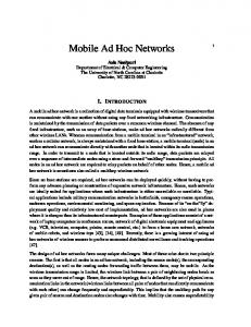
Our simulation network is created within a 1000m 1000m space with the “random way-point” mobility model [5]. In this model, each node stays stationary during its pause time, and starts moving to a randomly selected location with a random speed uniformly distributed between 0 and a certain maximum speed. We choose a maximum speed of 20 m/sec and pause time of 5 seconds to create a moderately dynamic network. When two nodes are within each other’s transmission range, a link is established between them. Our data is collected as follows: 1) at each simulation step, we compute the network topology based on the current location and transmission range of the nodes; 2) for each pair of nodes, we obtain their geometric distance and shortest path hop-count. We then group the collected , where data into brackets of distance , and obtain the average hop-count of the data samples in the brackets. We collect 100 data samples in each bracket. We perform two sets of simulations. In the first set, the transmission range of each node is fixed at 200m. The result from a medium density network (30 nodes) is shown in Figure 2(a). 1 Two observations are evident from this figure: 1) when the geometric distance of two nodes is less than the (identical) transmission range, the hopcount is always because they are neighboring nodes; 2) when the geometric distance of two nodes is longer than the transmission range, the average number of hops monotonically increases with distance. In our second set of simulations, we assign to each node a random transmission range uniformly distributed between 0 and 400m. The result in Figure 2(b) shows that there is no clear “cut-off” distance for one-hop routing, because the nodes have different transmission ranges. Again, it shows that the average number of hops monotonically increases with the geometric distance between two nodes. We will use this relation as a function between geometric distance and network distance later in this paper, to analyze the bandwidth cost and distribution delay of a tree.
������� � ��� � ��� � �"!
� � � � � ��#�#�#
�
III. L OCATION -G UIDED T REE C ONSTRUCTION A LGORITHMS In this section, we describe in detail the proposed location-guided tree construction algorithms (i.e., LGK, LGD and LGS). 1 The results from higher and lower density networks are similar, and are omitted for brevity.
INTERNATIONAL JOURNAL OF WIRELESS AND MOBILE COMPUTING
9 8
$
Number of Hops (hops)
7 6 5 4 3
1 number of hops between two nodes
0 0
200
400
600
800
1000
geometric distance (meters)
6
Number of Hops (hops)
5
4
�.7
3
2
1
number of hops between two nodes
0 0
200
400 600 geometric distance (meters)
800
1000
Relation between geometric distance and network distance.
A. Location-Guided K-ary (LGK) Tree
%
A location-guided k-ary (LGK) tree is constructed as follows: the sender node 1) selects the nearest destinations as children nodes, 2) groups the rest of the nodes to the children according to close geometric proximity, and 3) forwards a copy of the packet to each of the children with its corresponding sub-tree as destinations. The location-guided heuristic is greedy in the sense that a packet is always forwarded to the nearest nodes. The sub-tree grouping ensures that in the next step, the destinations will forward the packet to a set of nodes that are geometrically close to them, and hence reduces the overall cost of the packet distribution tree. The fan-out degree of the LGK tree algorithm plays an important role in deciding the shape of the tree: a small leads to a long-thin tree; a large leads to a short-fat tree.
%
%
%
%
%
%
%
�.4
�/7 �2(
�84
�8� 4 � 0��2* � �/9 � �.:;5 � 0 �.-?5 �)4 �/7
�24
(b) Under variable transmission range Fig. 2.
)� ( � �+* ��#�#�#,� �.�( 01�2* � �.3 � �.4 ��#�#�#,� �.-65 �+4
(a) Under fixed transmission range
$
% �'&
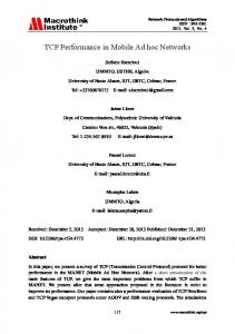
) as an example Here we use a binary tree ( to illustrate the tree construction and packet forwarding process, which starts from a sender node in a multicast group. We assume that the sender is aware of other members in the group. It then includes a list of the members as destinations in every packet it sends out. 2 Figure 3 illustrates how to construct a binary LGK tree. Only the participating nodes are shown in since that is the sender. the figure. The tree is rooted at has as its destination Node list. Based on the list, our LGK tree algorithm runs two consecutive steps: 1) children selection and 2) sub-tree clustering. In the first step, the algorithm selects two geometrically nearest nodes as the source node’s children. In the example, node and are selected because they are the nearest two nodes to . In case of equal distance, the tie is broken by a random selection of the nodes. In the second step, the algorithm goes through the rest of the destinations: if a destination is geometrically closer to , it is put into a sub-list designated as the destination list for ; otherwise, it is put into the destination list for . This ensures that later on, node and will find their destinations close to themselves. In the example, the list for is , and the list for is . When a destination has equal and , it is taken by the node with distances to both a shorter destination list to achieve better tree balancing. Subsequently, the original packet is replicated into two packets and then forwarded via unicast to and . After receiving the packet, node and each runs the tree construction algorithm to further forward the packet down to other destinations. This process stops when an in-coming packet has an empty destination list. A general algorithm to construct a tree with degree is similar to the binary tree example above, except that each time children are selected and sub-trees are clustered. In the case when a packet cannot be forwarded to a children node (no route), the packet is lost and the destination nodes in that sub-tree will not receive the packet. This situation may happen in a MANET because mobile nodes can shut itself down abruptly or move out of reach. Therefore, the sender should include only the “active” nodes as the packet’s destination nodes. This requires that each node periodically refreshes the membership of itself to the rest of the group. In our scheme, the membership refreshment is coupled with the location update mechanism (Section IV-A) where each node periodically updates its location to the rest of
�/(
2
4
%
2
��4
�/7
�/7
��4
%
�/7
�/7
%
The sender has the option of including only a subset of the group members as a packet’s destinations, which may be desirable for certain admission control purposes.
INTERNATIONAL JOURNAL OF WIRELESS AND MOBILE COMPUTING
5
n2
n1
n2
n1
n0 (sender)
n3
n4 n0 (sender)
n3
n5
n4 n5
n7 n9
n6 n9
n7
n6
n8
Fig. 3.
An example of LGK tree construction with
@BADC
n8
.
the group. A location update message not only updates a node’s new location, but also refreshes its group membership. If an update message is not received during a period, the node will be purged from the multicast group. Because of the periodic membership refreshment, the destination nodes are very likely to be reachable from the source node. B. Location-Guided Directional (LGD) Tree A location-guided directional (LGD) tree is constructed as follows. The sender 1) partitions the space into multiple cone areas centering around itself, 2) selects the nearest node in each cone area as its child, and 3) forwards a copy of the packet to each child with all the other nodes in the child’s cone area as its destinations. This heuristics ensures that the grouping of the subtrees are along approximately the same direction from the sender, and hence it reduces the overall cost of the tree. The fan-out angle of the cone area is an important factor in deciding the shape of the tree: a small angle (i.e. more cone partitions) leads to a short-fat tree; a large angle (i.e. fewer cone partitions) leads to a longthin tree. In the following, we illustrate the LGD tree construction process using an example in Figure 4. The has cone angle is 120 degree in this example. Node as its destination list. It partitions the space into three equal-size cone areas, and groups the nodes in each area into a sub-tree. After that, the sender selects the nearest node in each sub-tree as its child. In this example, nodes , and are selected. Their respective destination lists are , , and . Clearly, the partitioning of the cone areas is not unique, and there may be ways to improve such partitioning to better balance the tree. In our LGD algorithm, we simply partition the cone areas in a random fashion without taking other objectives into account. By choosing the number of cone partitions (and hence the fan-out angle), we can control the shape of the
�E(
0;� * � � 3 � � 4 ��#�#�#,� � - 5
�8= � �.> � �.-G5
0 �H:I5
�24 �.7
)� 9 � 0F� * � 3 5 0
Fig. 4. An example of LGD tree construction with 120 degree cone angle.
LGD tree similar to choosing different LGK algorithm.
%
values in the
C. Location-Guided Steiner (LGS) Tree A Steiner tree is commonly used as a packet distribution tree for efficient delivery of multicast packets in a fixed network. It spans over all nodes in a multicast group and minimizes the overall cost of the tree. Finding a Steiner tree in a network is a NP-hard optimization problem [6]. Under the well-known TakahashiMatsuyama heuristic [7], the multicast routing protocol generates a Steiner tree by an incremental approach. Initially the tree contains only the source node. At each iteration, the nearest unconnected destination to the partially constructed tree is found and the least-hop path between them is added to the tree. The distance is usually measured by the number of network-level hops. This tree construction process is repeated until all destinations are included in the tree. In a router-assisted multicasting approach, every node in a network can become a tree node to forward packets, in which case the constructed Steiner tree is near optimal. Our location-guided Steiner (LGS) tree is constructed using a modified version of the Takahashi-Matsuyama heuristic. The differences are: 1) we use geometric distance as a measurement of closeness; 2) only the group nodes can be used as tree nodes. Between the group nodes, data packets are encapsulated in unicast packets and forwarded via the underlying unicast routing protocol. Below we use an example to illustrate the construction of a LGS tree in Figure 5. Initially, the tree only contains the sender node . Within the remaining set of nodes , node is geometrically closest to . Therefore, is added into the tree with edge . In the second step, the remaining set of un-connected nodes are examined and the node closest to the partially constructed tree is selected. In the example, we compare
J �+* � �.3 ��#�#�#K� �.-ML �+( �H4 �4
�)( � (� 4
INTERNATIONAL JOURNAL OF WIRELESS AND MOBILE COMPUTING
n2
n1
n0 (sender)
n3
n4 n5
n7 n9
n6
n8
Fig. 5.
An example of LGS tree construction.
J �N* � �H�.( 3 � �8= ��#�#�#K� �.-ML
to each of the nodes in the unthe distance from connected set , as well as the distance from to that set, and select the shortest distance and . Therefore, is added to which is between the tree with edge . This process repeats until all the nodes have been included in the tree as shown in forwards a the figure. Subsequently, the sender node copy of the data packet to each of its children nodes, i.e., , , and , with their corresponding sub-trees as destinations. At each of the children nodes, a LGS tree is computed again to further forward the packet. This forwarding process repeats until the packet has reached all members of the group. Although the entire LGS tree can be computed at the source and included in the data packet, we choose to construct the tree hop-byhop, because this allows the intermediate nodes to utilize the latest location information of the destination nodes in the computation. The major difference between LGS and LGK/LGD trees is that the out-going degree of a tree node in LGS is not fixed. It depends on the outcome of the Steiner algorithm. In LGK, the out-going degree of a tree node is controlled by the parameter ; in LGD, it is controlled by the number of cone partitions. All these algorithms are guaranteed loop-less because a destination address will be removed from the list whenever a packet has reached the node; therefore, it cannot go back to that node again.
�/4
�3 �4
�( �7 �H(O�.7
�7
�E(
�7
%
IV. C OMPANION M ECHANISMS To augment and enhance the design of our locationguided tree construction algorithms, we introduce three companion mechanisms: 1) location/membership update, 2) address compression and 3) route caching. A. Location/Membership Update In the location-guided tree construction algorithms, we have assumed that the geometric locations of the group nodes are known to other nodes in the same group. Therefore, our tree construction algorithms have to be
6
augmented by a location update mechanism to disseminate location information among the group nodes. At the same time, the location updates also serve as group membership refreshments to detect dead or unreachable nodes. A node will be excluded from a source node’s destination list when its membership is not refreshed over a certain period of time. To this end, we propose a hybrid approach to location/membership update, which includes both in-band update and periodic update. In-band update takes place when a node has data packets to send. The sender always includes its geometric location in the header of every data packets it sends out. Consequently, the sender’s location will be learned by other members of the same group. Periodic update kicks in when a node has no data packets to send for an extended period of time. In that case it has to send out a special null packet just to inform other nodes of its current location. Since the location information is used by other nodes to construct a packet distribution tree, up-to-date location information will improve the optimality of the trees. B. Optimization by Address Compression A major disadvantage of our scheme is the space overhead of including the list of destination addresses in each data packet. For example, if a node is identified by an IPv4 address and there are 25 destination nodes, the overhead is 100 bytes in each packet. This overhead is even more significant in a large multicast group. We propose to reduce this overhead by compressing the list of destination addresses as follows: instead of using the IP address of each node, we use the index of the node in the multicast group as its identity. For example, if a group has 25 nodes, each node may be indexed from 0 to 24, which can be encoded in a 5-bit field. This reduces the space overhead from 100 bytes to 125 bits (or 16 bytes). In fact, a 48-byte address list can accommodate up to 64 group nodes, which is about the size of a medium multicast group. A node’s index is determined by the application server when it joins the group, and the server may reuse an index when a node leaves the group. After joining the group, the new node announces its existence to the group by sending out a multicast packet. The new node’s index and IP address are then recorded in each node’s address look-up table. Using this address compression technique, our scheme is able to accommodate a medium size multicast group. C. Optimization by Route Caching In order to forward a packet with multiple destinations, a node has to run one of the tree construction algorithms
INTERNATIONAL JOURNAL OF WIRELESS AND MOBILE COMPUTING
to decide how to forward the packet. We denote such a decision as a “route”. If the locations of the destinations have not changed, the outcome of the algorithms will not change either. Therefore, a node can cache the computed route and re-use the route next time when a new packet comes in with the same set of destinations. Therefore, it reduces the processing overhead in forwarding packets. A cached route will be invalidated only when a location update arrives from any of the destination nodes and the new location has significantly shifted from the original location. In a group of stationary nodes, the cached route will not be invalidated and hence there is zero computation overhead once the tree is set up. V. A NALYSIS OF LGK, LGD
AND
LGS T REES
In this section, we will analyze the bandwidth cost, distribution delay, space overhead, and computational complexity of the LGK, LGD and LGS trees. A. Bandwidth Cost Bandwidth cost of a multicast tree is commonly defined as the overall network-level hops of the tree. In this section, we analyze bandwidth cost of the LGK, LGD and LGS trees by their overall geometric distance of the tree. We have shown in Section II-B that using geometric distance to approximate network distance is feasible, because they are closely related to each other by a monotonic function. Below we consider bandwidth cost of a tree as its overall geometric distance of the tree edges. participating nodes A LGK tree spanning over always has edges regardless of the degree of the tree. There are two factors affecting the average edge distance. First, a forwarding node always selects the nearest children to forward the packet. If is small, the forwarding node will forward the packet to those nodes that are truly close, which makes the average edge distance small. Second, the sub-tree clustering process groups the rest of the nodes around the children nodes, picking a node with the smallest distance. If is large, there will be many sub-groups clustered close to each other, which makes the average edge distance small. Combining these two counter-active factors, a value between (smallest) and (largest) is likely to be optimal in reducing the bandwidth cost. We will test this hypothesis by simulation in Section VI-B. The shape of a LGD tree is controlled by the number of cone partitions. If the number of partitions is large, the sub-groups are clustered close to each other, and hence their further forwarding cost is small. At the same time, the cost of forwarding to the children is large because
�
�QPR�
%
%
�
%
�IPR�
%
%
7
there are fewer number of nodes to select from each sub-group. Combining these two counter-active factors, degree angle) and a partition number between 2 (i.e. N (i.e. degree angle) is likely to be optimal in reducing the bandwidth cost. Again, we will test this hypothesis by simulations in Section VI-C. A LGS tree for a group of nodes also has edges. The average edge distance of a LGS tree is usually smaller than that of a LGK or LGD tree because the heuristic is more greedy: an un-connected node has the option of connecting to any node in the partially constructed tree, and the algorithm always adds the nearest node into the tree in each iteration. Therefore, the overall cost of a LGS tree is usually smaller than the LGK and LGD trees.
�KS��
TVU��XWOY
�
�ZP��
B. Distribution Delay Distribution delay of a multicast tree is commonly defined as the number of network-level hops along the longest path from a sender to any of the receivers. In this section, we use geometric distance instead of network distance to measure the distribution delay (similar to the discussion of bandwidth cost above). For LGK trees, we consider two separate cases: 1) and 2) . In the first case ( ), the resulting structure is a “chain” topology. The delay along the chain is , where is the number of group nodes, and is the average geometric distance of a tree edge. This delay bound shows that the delay grows linearly with the number of nodes in a session. In the second case ( ), the resulting structure is a ary tree. The distribution delay is the height of the tree: , where is the number of group nodes, and is the average geometric distance of a tree edge, assuming that the tree is randomly built [8]. This result shows that distribution delay grows logarithmically with the number of nodes in a group. Therefore, LGK trees with are preferable than LGK trees with to reduce the distribution delay. For LGD trees, the minimal number of partitions is two. As a result, the distribution delay analysis is similar to a LGK tree with , i.e., it grows logarithmically with the number of nodes in a group. For LGS trees, the out-going degree of a node is determined by the relative locations of the nodes and is not fixed. In the worst case, the topology can become a linear “chain”, which gives a delay bound of , where is the number of group nodes and is the average geometric distance of a tree edge. However, in practice, the average height of a LGS tree is much lower than its worst case bound. We will show this result by simulation in Section VI-D.
% � �
% 5