unit square using the Twister and Whirlwind subclusters. The ODPDR and the OHPDR use 16 processors of Twister (16 nodes, 1. CPU per node); the OHPDR2 ...
Effective Out-of-Core Parallel Delaunay Mesh Refinement using Off-the-Shelf Software Andriy Kot, Andrey Chernikov and Nikos Chrisochoides The College of William and Mary Dept. of Computer Science Williamsburg, VA 23187-8795 USA {kot, ancher, nikos}@cs.wm.edu Abstract We present two cost-effective and high-performance outof-core parallel mesh generation algorithms and their implementation on Cluster of Workstations (CoWs). The total wall-clock time including wait-in-queue delays for the out-of-core methods on a small cluster (16 processors) is three times shorter than the total wall-clock time for the incore generation of the same size mesh (about a billion elements) using 121 processors. Our best out-of-core method, for mesh sizes that fit completely in the core of the CoWs, is about 5% slower than its in-core parallel counterpart method. This is a modest performance penalty for savings of many hours in response time. Both the in-core and outof-core methods use the best publicly available off-the-shelf sequential in-core Delaunay mesh generator.
1. Introduction Parallel mesh generation is a crucial building block for large-scale simulations on parallel platforms like CoWs. Parallel mesh generation procedures decompose the original mesh generation problem into smaller subproblems that can be solved (meshed) in parallel. The subproblems can be formulated to be either tightly or partially coupled or even decoupled. The coupling of the subproblems (i.e., the degree of dependency) determines the intensity of the communication and synchronization between the subproblems [6]. Tightly coupled mesh generation methods such as Parallel Optimistic Delaunay Mesh (PODM) generation method [16] are not suitable for out-of-core (OoC) computations due to very intensive communication among subdomains which leads to frequent (about 25K per second) disk This work was supported by NSF Career Award #CCR-0049086, ITR #ACI-0085969, NGS #ANI-0203974 and ITR #CNS-0312980.
1-4244-0054-6/06/$20.00 ©2006 IEEE
accesses. On the other hand, decoupled methods like Parallel Delaunay Domain Decoupling Method [15] use off-theshelf state-of-the-art sequential software like Triangle [18] and lead to very efficient OoC methods. However, these methods rely upon the solution of a very difficult problem which is open for 3-dimensional (3D) geometries [14]. The only suitable methods for OoC parallel Delaunay mesh generation are the partially coupled methods that: (1) do not rely on domain decompositions and (2) can use offthe-shelf existing sequential mesh generation libraries. It takes about ten to fifteen years to develop the algorithmic and software infrastructure for sequential industrial strength mesh generation libraries. Moreover, improvements in terms of quality, speed, and functionality are open ended and permanent which makes the task of delivering state-ofthe-art parallel OoC mesh generation codes even more difficult and expensive when they are written from scratch, i.e., without re-using the existing code. In [3, 4] we presented an in-core partially coupled Parallel Delaunay Refinement (PDR) method which relies upon a simple block data decomposition (see Figure 1, left). The data decomposition can be generated either with a uniform 2D/3D lattice or a quadtree (octree in 3D) covering the entire domain Ω. The block decomposition is used to guide the parallel refinement, so that the points, independently inserted in certain regions of Ω, are a priori Delaunayindependent. Our analysis indicates that the methods in [3, 4] are extendable to 3D geometries, however, this research is still in progress. In this paper we use the 2D PDR method to develop and analyze the performance of the parallel OoC guaranteed quality Delaunay mesh generation algorithms and their implementation. The 2D method is not as computationally intensive as the 3D PDR method and thus we expect that the performance data we present here will improve even further for the 3D case. Why OoC parallel mesh generation is an important prob-
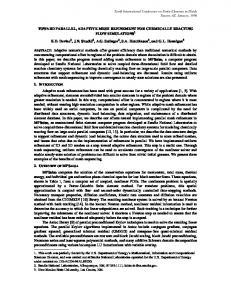
lem to solve? While it is possible to generate very large meshes in-core using parallel computers with large number of processors by using their aggregate memory, there are two main drawbacks to this approach: (1) mesh generation and refinement are memory-intensive tasks and do not require the computing power of hundreds of CPUs, and (2) requesting hundreds of nodes on large CoWs shared by multiple users can result in long wait-in-queue delays that increase substantially the total wall-clock time. Figure 1 (right) depicts the average and maximum wait-inqueue time statistics for parallel jobs on Sciclone cluster at the College of William and Mary. These data indicate that the average and the maximum wait-in-queue time for a parallel job with more than 128 processors is about 3 hours and 11 days, respectively. We address these concerns by presenting two OoC algorithms and their implementation for CoWs with both single processor nodes and k-way SMP nodes. Specifically, in Section 4 we present an OoC method for distributed memory machines with a single processor per node and in Section 5 we present a hybrid OoC method for CoWs with SMP nodes. Our performance data in Section 6 indicate that the total wall-clock time including wait-in-queue delays and total execution time for the hybrid OoC method is 3.3 times shorter than the total wall-clock time for the in-core generation of the same size meshes using more than one hundred processors. Although the hybrid OoC method exhibits about 5% overhead over the corresponding in-core method (for mesh sizes that fit completely in the core of the CoWs) this is a modest performance penalty for savings of many hours in response time. Both OoC codes use the best publicly available off-the-shelf sequential Delaunay mesh generator [18]. This helps us leverage the on-going improvements in terms of quality, speed, and functionality of sequential in-core Delaunay mesh generation methods.
2. Related Work There are two basic approaches for the out-of-core computing: implicit, usually involves virtual memory (VM) supported by internal mechanisms of an operating system (OS); and explicit, which often implies algorithm-specific optimizations. While VM is easy to employ it has a number of limitations. First, the amount of VM is limited to 4GB for a single process on 32-bit architectures (only 2GB under Windows and Linux since a half is reserved for the OS). Although the newer processors provide 64-bit address space the OSsupported VM is optimized for system throughput and usually cannot exploit access patterns of irregular and adaptive applications. In our tests an increase in problem size from From the last four and a half years.
23.8 million elements (fully in-core, 4 processors) to 58.8 million elements (doubling the amount of memory by using disk, 4 processors) resulted in an increase of the execution time from 418 seconds to more than 3 hours. Our out-ofcore methods generate meshes of that size (58.8 millions) in less than a half an hour on 4 processors. The explicit approach is usually employed to develop algorithm-specific out-of-core methods. This approach has been very effective in linear algebra parallel computations [7, 20]. Out-of-core linear algebra libraries use various mapping layouts (depending on the underlying I/O and algorithm specifics) to store out-of-core matrices and employ vendor supplied libraries for asynchronous disk I/O. They rely on high performance in-core subroutines of BLAS [10], LAPACK [8] and ScaLAPACK [5] and a simple non-recursive (in most cases) pipeline to hide latencies associated with disk accesses. Also, Salmon et al. [17] described an out-of-core N-body parallel method which is irregular but not adaptive, i.e., there is no creation or deletion of new bodies during the execution, unlike the parallel mesh refinement computation we focus on in this paper. Salmon et al. extend the virtual memory scheme to store out-of-core pages on the disk. They use an algorithm-specific space-filling curve to arrange data within memory pages. A problem-independent feature [17] is the page replacement algorithm which is based on the last recently used (LRU) replacement policy. The same policy is used as a basic virtual memory policy for many platforms (e.g., Linux). However, the authors extend it by introducing priorities, different aging speeds for different data types, and explicit page locking. Etree [21] is an out-of-core algorithm-specific approach for sequential mesh generation. The novelty of Etree is in the use of a spatial database to store and operate on large octree meshes. Each octant is assigned a unique key using the linear quadtree technique which is stored as a B-tree. There are three steps to generate a mesh with Etree: (1) create an unbalanced octree on disk, (2) balance the etree by decomposing further the octants that violate the 2-to-1 constraint, and (3) store the element-node relations and node coordinates in two separate databases. Subsequently, all the mesh operations are performed by querying the databases using Etree calls. This method targets octree meshes and it is exceptionally fast, especially after recent new improvements using a two-level bucket sort algorithm [22]. However, it targets octree-based meshes and is not parallel.
3. Parallel Delaunay Refinement Method The Parallel Delaunay Refinement (PDR) algorithm is based on a theoretical framework for constructing guaranteed quality Delaunay meshes in parallel [2–4]. Sequential guaranteed quality Delaunay refinement algorithms in-
1000000
100000
Tim e (sec)
10000
max
1000
average
100
10
1 32 to 47
48 to 63
64 to 95
96 to 127
128 and higher
# ofrequested processors
Figure 1. (Left) The pipe cross-section overlapped by a uniform lattice used by the PDR method. The squares in bold represent refinement blocks that are subdivided into smaller cells; and (right) the wait-in-queue time statistics for parallel jobs collected from the last four and a half years from a 300+ processor cluster at the College of William and Mary.
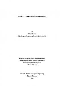
sert points at the circumcenters of triangles of poor quality or of unacceptable size. Two points are called Delaunayindependent iff they can be inserted concurrently without destroying the conformity and Delaunay properties of the mesh. In [3] we provide a sufficient condition of Delaunayindependence, which is based on the distance between points, i.e., two points are Delaunay-independent if the distance between them is no less than 4¯ r, where r¯ is an upper bound on triangle circumradius in the initial mesh. Evaluating the above criterion for every pair of candidate points is very expensive. In [3] we presented an efficient implementation which relies on the use of a coarse auxiliary lattice (see Figure 2). The lattice is imposed over the triangulation domain (see Figure 1, left) in such a way that the circumcenters in non-adjacent cells are a-priori Delaunayindependent. Processors are logically arranged into a twodimensional grid, and each processor is assigned some subset of cells for refinement. The parallel meshing in [3] is implemented by simultaneously shifting cells among processors. Buffer cells serve to separate the refinement zones. After every refinement iteration, the triangles in buffer cells are exchanged between neighboring processors and are used in subsequent refinement steps. Data exchange is organized by shifting cells along vertical, horizontal, and diagonal directions The PDR algorithm is partially coupled [6] with bulk communication and very simple and inexpensive data decomposition. Thus it is suitable for out-of-core parallel Delaunay mesh refinement. In [13] we presented a variation of the PDR algorithm for shared memory architectures (SPDR) and its out-of-core version (OSPDR).
4. Out-of-core Distributed Memory PDR The Out-of-core Distributed memory PDR (ODPDR) algorithm is designed to create very large meshes in parallel, using the aggregate and concurrent access of disk space through multiple nodes of a CoW. The following assumptions were made for the design of the ODPDR algorithm: (1) parts of the mesh stored on disk can only be accessed by the processor that the disk is directly attached to; (2) only a small fraction of the mesh can be loaded into the system memory, and (3) network and disk accesses have a very high latency. Therefore our goal in ODPDR is to minimize the number of accesses and overlap them with computation whenever possible. The mesh is stored on disk as a collection of subdomains. The subdomains are generated from the block decomposition (using the auxiliary lattice) we used for the PDR method. The ODPDR uses different from PDR assignment of the cells to processors, but relies on the PDR (in-core) parallel Delaunay meshing and refinement code. Optimal data distribution reduces the amount of communication to a necessary minimum and consequently lowers associated latencies. We propose an interleaving block partitioning (see Figure 3, left). That is the domain is partitioned into N 2 subdomains, where N is a number related to the size of the mesh and the amount of available RAM. Each subdomain is further partitioned into P blocks, where P is the total number of processors. Since P is a constant for every configuration, N is chosen such that the memory requirements of any single block is small enough to fully fit into RAM of a single node. The total number of blocks in the domain is P × N 2 ; each processor stores (on local disk) one block from each subdomain, total of N 2 blocks. This scattered decomposition helps to implicitly improve work-
(0)
(1)–(2)
(3)–(4)
(5)–(6)
(7)–(8)
(9)–(10)
Figure 2. Snapshots of a mesh distributed among four processors. Dark areas are the parts of the mesh that have already been refined. Grey areas are those that have not been refined. Each processor starts with an initial coarse mesh and ends up with a refined mesh covering the same area.
load imbalances. N
N
P
P N
1 3 1 3 1 3
ppn
2 4 2 4 2 4
1 3 1 3 1 3
2 4 2 4 2 4
1 3 1 3 1 3
2 4 2 4 2 4
K
N
11 12 11 12 11 12 21 22 21 22 21 22 11 12 11 12 11 12 21 22 21 22 21 22 11 12 11 12 11 12 21 22 21 22 21 22
Figure 3. An example of domain partitioning for the ODPDR (left) and the OHPDR (right) methods.
There are four refinement steps in the PDR method, each step is followed by data exchanges or shifts. Due to insuffi-
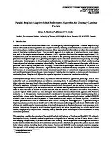
cient (relatively to the problem size) memory it is impossible to perform all of the shifts simultaneously as in the PDR. The ODPDR method uses two levels of data movements: (1) from the disk to the memory which we call a top-level shift and (2) from one processor to another which we call a shift, in consistence with our previous work (PDR). There are two distinct types of top-level shifts: horizontal/vertical and diagonal. We designed the diagonal shift to be more efficient than a simple sequence of horizontal/vertical shifts; therefore, it requires a separate explanation. We will describe each shift type using one direction as an example, and the remaining directions can be easily understood by analogy. In particular, we will focus on the horizontal shift to the right and the diagonal shift to the right and down. The horizontal/vertical type of top-level shift is rather straightforward, the order of refinement coincides with the
direction of the shift (see Figure 4): ¯ ρ¯, P , p, N ) ODPDR.H ORIZONTAL S HIFT(M, ∆, Input: M is a Delaunay mesh computed in previous phase(s) X is a planar straight line graph which defines the domain Ω ¯ and ρ¯ are desired upper bounds on triangle area ∆ and circumradius-to-shortest edge √ ratio, respectively P is the total number of processors ( P is integer) p is the index of the current processor, 1 ≤√p ≤ P N is the total number of subdomains (N/ P is integer) Output: a (partially) refined Delaunay mesh Mp which conforms to X ¯ and ρ¯ and respects (in certain regions) ∆ 0 Calculate row(p) and column(p) of the current processor √ // 1 ≤ row(i), column(i) ≤ P , 1 ≤ i ≤ P 1 for m = 1, . . . , N 2 for n = 1, . . . , N 3 Load block p of subdomain (m − 1) × N + n as local mesh Mp 4 if n �= 0 and col(p) = 1 5 Receive cells {ci,1 | 1 ≤ i ≤ 4} of local mesh Mp 6 endif ¯ ρ¯, P , p) 7 Mp ← P DRref inement (Mp , ∆, ¯ 8 Mp ← P DR √ shif ts (Mp , ∆, ρ¯, P , p) 9 if col(p) = P and n �= N 10 Send cells {ci,4 | 1 ≤ i ≤ 4} to processor in (row(p), 1) 11 endif 12 Store local mesh Mp as block p of subdomain (m − 1) × N + n 13 endfor 14 endfor 15 return Mp
The diagonal shift is more complex, because the corner cell shifts both horizontally and vertically and both groups of side cells shift into their respective directions (see Figure 4): ¯ ρ¯, P , p, N ) ODPDR.D IAGONAL S HIFT(M, ∆, Input: same as in ODPDR.HorizontalShift Output: a (partially) refined Delaunay mesh Mp which conforms to X 0 Calculate row(p) and column(p) of √ the current processor // 1 ≤ row(i), column(i) ≤ P , 1 ≤ i ≤ P 1 for m = 1, . . . , N 2 for n = 1, . . . , N 3 Load block p of subdomain (m − 1) × N + n as local mesh Mp 4 if n �= 0 and col(p) = 1 5 Receive cells {ci,1 | 1 ≤ i ≤ 3} of local mesh Mp 6 endif ¯ ρ¯, P , p) 7 Mp ← P DRref inement (Mp , ∆, ¯ 8 Mp ← P DR √ shif ts (Mp , ∆, ρ¯, P , p) 9 if col(p) = P and n �= N 10 Send cells {ci,4 | 1 ≤ i ≤ 3} to processor in (row(p), 1) 11 endif √ 12 if row(p) = P and m �= N 13 Send cells {c4,i | 1 ≤ i ≤ 3} to processor in (1, col(p)) 14 endif 15 if p = P and n �= N and m �= N
16 17 18 19 20
21 22 23 24
25 26 27 28 29
Send cell c4,4 to processor in (1, 1) endif if row(p) = 1 and m < N Receive cells {b1,i | 1 ≤ i ≤ 3} of local buffer B Overwrite cells {c1,i | 1 ≤ i ≤ 3} of block p in in subdomain m × N + n with the content of B endif if n < N and m < N Receive cell b1,1 of local buffer B Overwrite cell c1,1 of block p in subdomain m × N + n + 1 with the content of B endif Store local mesh Mp as block p of subdomain (m − 1) × N + n endfor endfor return Mp
5. Out-of-core Hybrid Memory PDR Our experimental study showed that ODPDR method performs best when used on distributed memory multiprocessors with single processor per node (see section 6). However, single-processor nodes are rather uncommon today; therefore, to take advantage of k-way SMP machines we designed and implemented the Out-of-core Hybrid memory PDR (OHPDR). We made the same design assumptions as in the case of the ODPDR, additionally, processors of the same node have equal access time to its local disk. The mesh is stored on disks as a collection of subdomains generated from the block decomposition (using the auxiliary lattice). Part of the code responsible for meshing is taken from the OSPDR, but the assignment of cells to processors is different. We use an interleaving partition similar to the one used in the ODPDR (see Figure 3, right). The mesh is divided into N 2 subdomains, where N is a number related to the size of the mesh and the amount of available RAM. Each subdomain is then subdivided into ppn × K blocks, where K is the number of SMP nodes and ppn is the number of processors per node. The value of N is chosen in the same way we chose the number of subdomains for the ODPDR method. The OHPDR also (as the ODPDR) uses the same two levels of data movements. However, a shift can be either shared (between processors of an SMP) or distributed, over the network (between nodes). Similarly, there are two distinct types of top-level shifts: horizontal/vertical and diagonal. Due to the limited space, we will only focus on the horizontal shift to the right and the diagonal shift to the right and down (the rest is done by analogy). A top-level horizontal shift is performed in the following steps (see Figure 4):
¯ ρ¯, K, ppn, p, N ) OHPDR.H ORIZONTAL S HIFT(M, ∆, Input: ppn is the number of processors per node (the same number of processors on all nodes) √ K is the number of nodes (we assume K ∗ ppn is integer and, for simplicity of the presentation, K = ppn) p is the index of the current processor, 1 ≤ p ≤ ppn × K ¯ ρ¯ and N are the same as in ODPDR.HorizontalShift M, X , ∆, Output: a (partially) refined Delaunay mesh Mp which conforms to X ¯ and ρ¯ and respects (in certain regions) ∆ 0 Calculate node(p) and proc(p) of the current processor // 1 ≤ node(i) ≤ K, 1 ≤ proc(i) ≤ ppn, 1 ≤ i ≤ ppn × K 1 for m = 1, . . . , N 2 for n = 1, . . . , N 3 Load block p of subdomain (m − 1) × N + n as local mesh Mp 4 if n �= 0 and proc(p) = 1 5 Read cells {ci,1 | 1 ≤ i ≤ 4} of local mesh Mp from shared-memory buffer 6 endif ¯ ρ¯, ppn, K, p) 7 Mp ← SP DRref inement (Mp , ∆, ¯ ρ¯, ppn, K p) 8 Mp ← SP DRshif ts (Mp , ∆, 9 if proc(p) = ppn and n �= N 10 Write cells {ci,4 | 1 ≤ i ≤ 4} into shared-memory buffer 11 endif 12 Store local mesh Mp as block p of subdomain (m − 1) × N + n 13 endfor 14 endfor 15 return Mp
The top-level diagonal shift to the right and down is performed in the following steps (see Figure 4): ¯ ρ¯, K, ppn, p, N ) OHPDR.D IAGONAL S HIFT(M, ∆, Input: same as in OHPDR.HorizontalShift Output: a (partially) refined Delaunay mesh Mp which conforms to X 0 Calculate node(p) and proc(p) of the current processor // 1 ≤ node(i) ≤ K, 1 ≤ proc(i) ≤ ppn, 1 ≤ i ≤ ppn × K 1 for m = 1, . . . , N 2 for n = 1, . . . , N 3 Load block p of subdomain (m − 1) × N + n as local mesh Mp 4 if n �= 0 and proc(p) = 1 5 Read cells {ci,1 | 1 ≤ i ≤ 3} of local mesh Mp from shared-memory buffer 6 endif ¯ ρ¯, ppn, K, p) 7 Mp ← SP DRref inement (Mp , ∆, ¯ ρ¯, ppn, K, p) 8 Mp ← SP DRshif ts (Mp , ∆, 9 if proc(p) = ppn and n �= N 10 Write cells {ci,4 | 1 ≤ i ≤ 3} into shared-memory buffer 11 endif 12 if node(p) = K and m �= N 13 Send cells {c4,i | 1 ≤ i ≤ 3} to node node(p) 14 endif 15 if proc(p) = ppn and node(p) = K and n �= N and m �= N 16 Send cell c4,4 to node 1 17 endif 18 if node(p) = 1 and m < N
19 20 21 22 23 24
25 26 27 28 29
Receive cells {b1,i | 1 ≤ i ≤ 3} of local buffer B Overwrite cells {c1,i | 1 ≤ i ≤ 3} of block p in in subdomain m × N + n with the content of B endif if n < N and m < N Receive cell b1,1 of local buffer B Overwrite cell c1,1 of block p in subdomain m × N + n + 1 with the content of B endif Store local mesh Mp as block p of subdomain (m − 1) × N + n endfor endfor return Mp
6. Performance Evaluation The evaluation of the OSPDR, ODPDR and OHPDR algorithms was performed on SciClone cluster. We used 4-way SMP nodes of subcluster “Hurricane” (4 quad-cpu Sun Enterprise 420R servers @ 450 MHz w/ 4 GB memory and 18.2 GB local disk), 2-way SMP nodes of subcluster “Twister” (32 dual-cpu Sun Fire 280R servers @ 900 MHz w/ 2 GB memory and 72.8 GB local disk) and singleprocessor nodes of subcluster “Whirlwind” (64 single-cpu Sun Fire V120 servers @ 650 MHz w/ 1 GB memory and 36.4 GB local disk). All algorithms are independent of the geometry of the domain, however, for our performance evaluation we used a square geometry to eliminate other parameters like work load imbalance. We also tested it with a mesh of cross section of a pipe model that is part rocket fuel system (see Figure 1, left). This test geometry shows that the impact of load imbalances is much more severe to the in-core PDR algorithms compared to its OoC counterparts we present here. In order to compare the performance of the in-core and OoC PDR methods which run on different configurations, we introduce a notion of normalized speed. This new measure computes the number of elements generated by a single processor over a unit time period, and it is given by V = TN ×P , N is the number of elements generated, P is the number of processors in the configuration and T is the total execution time. Table 1 shows the performance of all three out-of-core methods on a single 4-way SMP node from the “Hurricane” subcluster. The PDR performance is also included for comparison. However, the PDR has to use 9 and 16 processors, respectively for the second and the third problems since they would not fit in the aggregate memory of fewer processors. As expected OSPDR and OHPDR show the best performance (not including the PDR). The ODPDR does not take advantage of shared memory and thus is slower. These data http://www.compsci.wm.edu/SciClone/index.html.
suggest that the OHPDR method is about 5% slower than its counterpart in-core PDR method for the mesh sizes that fit completely in the core of the CoWs. Table 1. Parallel Delaunay refinement for a mesh of a unit square using the Hurricane subcluster. The OSPDR, the ODPDR and the OHPDR use 4 processors; the PDR uses 4, 9 and 16 processors. Mesh size, # elements ×106 23.8 58.8 109.3 175.4
PDR
OSPDR ODPDR OHPDR normalized speed (103 triangles per sec per proc) 12.22 5.95 5.31 5.54 13.33 8.89 7.94 8.77 12.35 11.32 10.38 11.68 n/a 10.19 9.31 9.96
Table 2 shows the performance of distributed memory out-of-core PDR methods along with the in-core PDR using up to 121 processors. The unit square is used as a test case. The OHPDR is tested on two slightly different configurations: (1) using 16 nodes with a single processor per node, listed as OHPDR and (2) using 8 nodes with two processors per node, listed as OHPDR2. The OSPDR being designed solely for shared memory cannot run on these configurations. Table 2. Parallel Delaunay refinement for the unit square using the Twister and Whirlwind subclusters. The ODPDR and the OHPDR use 16 processors of Twister (16 nodes, 1 CPU per node); the OHPDR2 uses 16 processors of Twister (8 nodes, 2 CPUs per node); the PDR uses up to 121 processors. Mesh size, # elements ×106 109.3 175.4 255.0 352.6 470.7 587.8 738.9 873.5
PDR
ODPDR OHPDR OHPDR2 normalized speed (103 triangles per sec per processor) 23.24 13.06 13.01 13.91 23.78 12.17 12.22 12.69 24.01 12.06 12.25 12.4 24.23 12.01 11.9 12.43 25.1 12.3 12.24 12.68 24.6 13.02 13.12 13.13 24.63 12.92 13.02 13.38 24.55 13.1 13.06 13.5
On SMP nodes the OHPDR (listed as OHPDR2) performs slightly better. This is expected since a substantial part of communication is done inside the SMP node using shared memory as opposed to ODPDR where all data The total number of nodes in the “Hurricane” subcluster is 16 and it is not possible to generate in-core meshes larger than 109.4 million triangles.
transfers happens over network. The normalized speed of the parallel OoC methods is approximately constant for all large problem sizes we ran. This suggests that the parallel OoC methods scale very well with respect to the problem size. The total execution time for about 0.9 billion elements is a little over one hour (one hour and seven minutes) using parallel OoC methods and 16 processors. However the wait-in-queue delays for parallel jobs with more than 100 processors —they are required to generate the same size mesh using the in-core PDR— in our cluster is on average about five hours. While on the same cluster the waiting time for 16 processors is less than half an hour. This makes the OHPDR2 response time 3.3 times shorter than the response time of the in-core PDR, for mesh sizes close to a billion elements. Table 3. Parallel Delaunay refinement for a mesh of the pipe model using the Twister and Whirlwind subclusters. The ODPDR and the OHPDR use 16 processors of Twister (8 nodes, 2 CPUs per node); the PDR uses varying number of processors. Mesh size, # elements ×106 58.3 91.1 131.2 178.6 233.3 295.3 364.6 441.1
PDR
ODPDR OHPDR normalized speed triangles per sec per proc) 16.12 9.42 9.96 15.18 8.42 8.84 14.29 8.31 8.32 14.35 8.01 8.39 13.3 8.31 8.33 14.08 8.81 8.89 15.72 8.73 8.83 17.2 9.09 9.46
(103
Table 3 shows the performance of distributed and shared memory methods along with the PDR on large configurations for an irregular geometry, the pipe model. The uniform block data decomposition we used for the pipe model results in an uneven distribution of work to processors. This load imbalance reduces the speed for both the in-core method (by 64%) and the OoC method (by 26%). However, in the case of OoC methods, at every point of time processors refine only a portion of over-decomposed [1] mesh, with all processor working in close proximity of each other. As a result the workload is implicitly balanced because by far all processors have to perform the same amount of computation.
7. Summary We presented two OoC methods for parallel guaranteed quality Delaunay mesh generation. First, the distributed
memory PDR method which extends the maximum size of the meshes we can generate compared to its counterpart shared memory OoC PDR methods [13]. Second, a combination of the OoC shared and distributed memory PDR method which is efficient for CoWs with k-way SMP nodes. The OoC methods are cost-effective (in terms of response time). The total wall-clock time including wait-in-queue delays and total execution time for the OoC methods is 3.3 times shorter than the total wall-clock time for the in-core generation of the same meshes using more than one hundred processors. Our best out-of-core method is only about 5% slower than its counterpart in-core method for mesh sizes that fit completely in the core of the CoWs. This is a modest performance penalty for savings of many hours in response time and power consumption. Moreover, both OoC codes use the best publicly available off-the-shelf sequential Delaunay mesh generator and thus leverage from on-going improvements in terms of quality, speed, and functionality of the sequential in-core Delaunay mesh generation methods. Although the data we presented are from 2D geometries, the contribution of this paper is still important for two reasons: (1) the memory management for 3D remains the same and thus the overheads for the 3D geometries will be much smaller since the 3D sequential mesher (Pyramid [19]) is more computationally intensive than its 2D counterpart (Triangle) which is the in-core mesh generation kernel we use and (2) 2D mesh generation is still important for some 3D simulations like direct numerical simulations of turbulence in cylinder flows (“drag” crisis simulations) with very large Reynolds numbers [9] and coastal ocean modeling for predicting storm surge and beach erosion in real-time [23]. In both cases, 2D mesh generation is taking place in the xy-plane and it is replicated in the z-direction in the case of cylinder flows or using bathemetric contours in the case of coastal ocean modeling applications. With the increase of the Reynolds number, the size of the mesh (in drag crisis simulations) grows in the order of Re9/4 [12], which motivates the use of parallel out-of-core mesh generation algorithms. Similarly, we have seen the difference in damages few inches (in the z-direction) made in two recent hurricanes in the Gulf Coast, this suggests very high resolution (and thus generation of very large meshes) for predicting storm surge and beach erosion. Our future work is directed toward improving the performance of disk memory using commercial off-theshelf databases, a highly efficient technology for out-ofcore query-based computations like OoC mesh generation. Finally, we are developing an out-of-core algorithmindependent framework using the percolation model of the HTMT Petaflops design [11], for relatively easy conversion of existing (in-core) parallel mesh generation codes to outof-core ones.
8
Acknowledgments
The experimental work was performed using computational facilities at the College of William and Mary which were enabled by grants from Sun Microsystems, the NSF, and Virginia’s Commonwealth Technology Research Fund. We are grateful to Tom Crocket for making available to us the wait-in-queue time statistics from Sciclone.
References [1] K. Barker, A. Chernikov, N. Chrisochoides, and K. Pingali. A load balancing framework for adaptive and asynchronous applications. IEEE Transactions on Parallel and Distributed Systems, 15(2):183–192, Feb. 2004. [2] A. N. Chernikov and N. P. Chrisochoides. Parallel guaranteed quality planar Delaunay mesh generation by concurrent point insertion. In 14th Annual Fall Workshop on Computational Geometry, pages 55–56. MIT, Nov. 2004. [3] A. N. Chernikov and N. P. Chrisochoides. Practical and efficient point insertion scheduling method for parallel guaranteed quality Delaunay refinement. In Proceedings of the 18th International Conference on Supercomputing, pages 48–57. ACM Press, 2004. [4] A. N. Chernikov and N. P. Chrisochoides. Parallel 2D graded guaranteed quality Delaunay mesh refinement. In Proceedings of the 14th International Meshing Roundtable, pages 505–517. Springer, Sept. 2005. [5] J. Choi, J. Dongarra, R. Pozo, and D. Walker. Scalapack: A scalable linear algebra for distributed memory concurrent computers. In In Proceedings of the 4th Symposium on the Frontiers of Massively Parallel Computation, 1992. [6] N. Chrisochoides. A survey of parallel mesh generation methods. Technical Report SC-2005-09, Division of Applied Mathematics, Brown University, 2005. [7] E. F. D’Azevedo and J. Dongarra. The design and implementation of the parallel out-of-core scalapack lu, qr, and cholesky factorization routines. Concurrency Practice and Experience, 12(15):1481–1493, 2000. [8] J. Demmel, J. Dongarra, J. D. Croz, A. Greenbaum, S. Hammarling, and D. Sorensen. Prospectus for the development of a linear algebra library for high-performance computers. Technical Report ANL/MCS-TM-97, 9700 South Cass Avenue, Argonne, IL 60439-4801, USA, 1987.
[9] S. Dong, D. Lucor, and G. E. Karniadakis. Flow past a stationary and moving cylinder: DNS at Re=10,000. In 2004 Users Group Conference (DOD UGC’04), pages 88–95, 2004. [10] J. J. Dongarra, J. Du Croz, S. Hammarling, and R. J. Hanson. An extended set of FORTRAN Basic Linear Algebra Subprograms. ACM Transactions on Mathematical Software, 14(1):1–17, 1988. [11] G. Gao, K. K. Likharev, P. C. Messina, and T. L. Sterling. Hybrid Technology Multithreaded Architecture. Proc. Frontiers, pages 98 – 105, February 1996. Annapolis, MD. [12] G. Karnriadakis and S. Orszag. Nodes, modes, and flow codes. Physics Today, 46:34–42, 1993. [13] A. Kot, A. Chernikov, and N. Chrisochoides. Outof-core parallel delaunay mesh generation for shared memory machines. In Proceedings of the 17th IMACS World Congress Scientific Computation, Applied Mathematics and Simulation, July 2005. [14] L. Linardakis and N. Chrisochoides. Medial axis domain decomposition for 2D geometries. ACM TOMS, submitted, Dec 2005. [15] L. Linardakis and N. Chrisochoides. Delaunay Decoupling Method for Parallel Guaranteed Quality Planar Mesh Refinement SIAM Journal on Scientific Computing, volume 27, issue 4, pages 1394-1423, 2006 [16] D. Nave, N. Chrisochoides, and L. P. Chew. Guaranteed: quality parallel Delaunay refinement for restricted polyhedral domains. In SCG ’02: Proceedings of the eighteenth annual symposium on Computational geometry, pages 135–144. ACM Press, 2002. [17] J. Salmon and M. Warren. Parallel out-of-core methods for N-body simulation. In Proceedings of the Eighth SIAM Conference on Parallel Processing for Scientific Computing, 1997. [18] J. R. Shewchuk. Triangle: Engineering a 2D Quality Mesh Generator and Delaunay Triangulator. In M. C. Lin and D. Manocha, editors, Applied Computational Geometry: Towards Geometric Engineering, volume 1148 of Lecture Notes in Computer Science, pages 203–222. Springer-Verlag, May 1996. From the First ACM Workshop on Applied Computational Geometry. [19] J. R. Shewchuk. Delaunay Refinement Mesh Generation. PhD thesis, Carnegie Mellon University, 1997.
[20] S. Toledo and F. Gustavson. The design and implementation of solar, a portable library for scalable outof-core linear algebra computations. In 4th Annual Workshop on I/O in Parallel and Distributed Systems, pages 28–40, 1996. [21] T. Tu and D. R. O’Hallaron. A computational database system for generatinn unstructured hexahedral meshes with billions of elements. In SC ’04: Proceedings of the 2004 ACM/IEEE conference on Supercomputing, page 25, Washington, DC, USA, 2004. IEEE Computer Society. [22] T. Tu and D. R. O’Hallaron. Extracting hexahedral mesh structures from balanced linear octrees. In Proceedings of the 13th INternational Meshing Roundtable, 2005. [23] R. A. Walters. Coastal Ocean Models: Two useful finite element methods. Recent Developments in Physical Oceanographic Modelling: Part II, 25:775–793, 2005.
2 4 2 4
1 3 1 3
2 4 2 4
2 4 2 4
1 3 1 3
11 12 11 12 11 12 21 22 21 22 21 22 11 12 11 21 22 21 11 21
11 21 11 21
12 22 12 22
11 12 11 12 11 21 22 21 22 21 11 21
12 22 12 22
11 12 11 12 11 12 21 22 21 22 21 22 11 12 11 12 11 12 21 22 21 22 21 22 11 12 11 12 21 22 21 22 11 12 11 12 11 21 22 21 22 21 11 21
12 22 12 22
11 12 11 12 11 12 21 22 21 22 21 22
12 22 12 22
11 12 11 12 11 12 21 22 21 22 21 22
11 12 11 12 11 12 21 22 21 22 21 22
11 12 11 12 11 12 21 22 21 22 21 22 11 12 11 12 11 12 21 22 21 22 21 22
11 12 11 12 11 12 21 22 21 22 21 22
2 block subdomain
1 3 1 3
step 1
1 3 1 3
11 12 11 12 11 12 21 22 21 22 21 22
step 2
2 4 2 4 2 4 2 4 2 4 2 4
step 3
1 3 1 3 1 3 1 3 1 3 1 2 1 2 1 3 4 3 4 3 2 4 2 4
2 4 2 4 2 4 2 4
OHPDR Diagonal shift (right and down)
step 4
1 3 1 3 1 3 1 2 1 3 4 3
OHPDR Horizontal/Vertical shift (right)
step 2
2 4 2 4
1 3 1 3
2 4 2 4
step 3
1 3 1 3
1 3 1 3
step 4
2 4 2 4 2 4 2 4 2 4 2 4 2 4
step 1
1 3 1 3 1 3 1 3 1 3 1 3 1 2 1 2 1 3 4 3 4 3 2 4 2 4
2 4 2 4 2 4 2 4 2 4
step 2
1 3 1 3 1 3 1 3 1 2 1 3 4 3
step 3
2 4 2 4 2 4
step 4
step 1 step 2 step 3 step 4
1 3 1 3 1 3
step 1
ODPDR Diagonal shift (right and down)
ODPDR Horizontal/Vertical shift (right)
21
processor assignment (ODPDR) node/processor assignment (OHPDR)
cell stored on disk cell loaded to ram
processed cell, stored on disk active buffer
buffer stored in ram
buffer stored on disk
data movements (shifts) between nodes
between procs.
Figure 4. Out-of-core schemes of top-level shifts for ODPDR (4 processors, 9 subdomains, distributed memory and disk storage) and OHPDR (2 nodes, 2 processors with shared memory per node, 9 subdomains, disk storage).