Effects of A-D Conversion Nonidealities on Distributed Sampling in Dense Sensor Networks * Sinem Coleri Ergen
Pravin Varaiya
Department of Electrical Engineering and Computer Sciences Berkeley CA 94720
Department of Electrical Engineering and
Computer Sciences Berkeley CA 94720
[email protected]
[email protected]
ABSTRACT We address the effect of the errors occurring at the analogto-digital converter (ADC), from quantization noise, circuit noise, aperture uncertainty and comparator ambiguity, on the accuracy of sensor field reconstruction. We focus on the oversampling of bandlimited sensor fields in a distributed processing environment. It has previously been shown that Pulse Code Modulation (PCM) style sampling fails to decrease the quantization error above some finite sampling rate. We show that the dither-based scheme, developed to decrease the quantization error, fails to decrease random errors associated with circuit noise, aperture uncertainty and comparator ambiguity. We propose an advanced ditherbased sampling scheme with the goal of reducing both kinds of errors by increasing the density of the sensor nodes. It is based on distributing the task of improving the quantization error and random error among the nodes. The error of the scheme is shown to be O( / ) for oversampling rate r. The maximum energy consumption per node is O(log(r)). Finally, the bit rate of the scheme is O( ,/2Iiog(r)) and it offers robustness to node failures in terms of a graceful degradation of reconstruction error. Categories and Subject Descriptors: C.2.4 [Distributed Systems] General Terms: measurements, performance, design. Keywords: distributed sampling, sensor networks, ADC, energy, accuracy, fault tolerance.
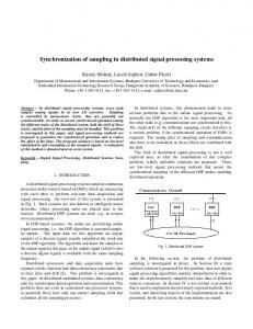
Figure 1: System for reconstructing sensor field.
hops, to a central controller. The central controller finally reconstructs the field. Increasing the density of the nodes in this sensor network setting is expected to improve the accuracy of the reconstructed sensor field. However, if all the error sources are not taken into consideration, the configuration of the nodes may fail to provide any improvement above some density. This paper focuses on the accuracy of the sensor field reconstruction based on the quantized samples of the sensor nodes by considering all types of errors occurring at the analog-todigital converter (ADC) for bandlimited sensor fields. Most physical signals are approximately bandlimited so can be reconstructed in a stable manner from the samples taken slightly above the Nyquist rate on a uniform lattice. In practice however the errors occurring in the ADC, namely quantization noise, circuit noise, aperture uncertainty and comparator ambiguity, cause unavoidable signal reconstruction errors. The only error mechanism present in an ideal ADC is quantization. This error arises in the transformation of the analog input signal that may assume any value within the input range of the ADC into finite precision output data. In physical ADC devices, on the other hand, there are additional error mechanisms. Aperture uncertainty comes about because an ADC does not sample the input signal at the precise sampling time and location. Comparator ambiguity is due to the finite speed with which transistors in the comparator are able to respond to a small voltage difference. Previous studies [1, 7, 3, 4, 5] have focused on two sampling schemes to reduce quantization error via oversampling in ADCs: Pulse Code Modulation (PCM) style sampling and dither-based sampling scheme. In PCM style sampling, the signal is sampled regularly at constant period r and then quantized with a step q. Then the signal is reconstructed by low-pass filtering the sequence of quantized samples with cut-off frequency equal to the signal bandwidth. In [1], it is
1. INTRODUCTION
Figure 1 illustrates a system for reconstructing sensor field F(x, y, z, t) based on the quantized samples at L sensor nodes. Each node i samples and quantizes the sensor field at location (x., Yi, zi). The quantized samples are then sent over the communication channel, which may have multiple
*Research supported by ARO-MURI UCSC-WNllNF-05-1-
0246-VA-09/05.
Permission to make digital or hard copies of all or part of this work for personal or classroom use is granted without fee provided that copies are not made or distributed for profit or commercial advantage and that copies bear this notice and the full citation on the first page. To copy otherwise, to republish, to post on servers or to redistribute to lists, requires prior specific permission and/or a fee. IPSN'06, April 19-21, 2006, Nashville, Tennessee, USA. Copyright 2006 ACM 1-59593-334-4/06/0004 ...$5.00.
202
structed from the samples at regular intervals T = , { }nEZ, with k-bit quantizer. Proposition 1: /2] For each A > 1, there exists a Airbandlimited kernel g(x) such that Cx - SuPxE (EZn g(xX - n ) I2) < oc and I (1) f(x) = E f -),Vx E R
shown that the quantization error in this sampling scheme can be modelled as a white noise independent of the input if the quantization step is small enough and a sufficiently large number of quantization levels is available. According to the white noise model, the conversion accuracy improves in proportion to the sampling interval r. In [7], however, it is shown that the accuracy improvement by a factor r is valid only in a small range of parameters q and r and the error does not tend to zero as r decreases but reaches a floor level for some finite -r. This is reasonable since the quantization error becomes correlated as T decreases. To improve the quantization error, a dither-based sampling scheme has recently been proposed. Dither-based sampling is based on recording positions of quantization threshold crossings of the input signal added to a deterministic dither function. [3] shows that the conversion accuracy im-
n
An)g(x
An example g is such that Ig(w)( - O for IwI > Air, g(w) = for lwl < r and 0 < g(w) < 1 for r < lwl < A7r. K-bit quantization perturbs the samples f(Q) by e, such that f(n) f(n) + En, in which IEn < 2 -k. In [1], it is shown that the quantization error can be modelled as a white noise independent of the input if the quantization step is small enough and a sufficiently large number of quantization levels is available. According to the white noise model, the reconstructed mean-square error is upper-bounded as
2 Moreover, representing quantization threshold crossing requires only a logarithmic increase of the bit rate in contrast to PCM style sampling scheme. The above schemes assume an ideal ADC so only quantization error is present. It is not clear however how other sources of errors affect the reconstruction performance. This paper aims to describe and analyze the effect of these random error sources in more detail. We show that a dither based scheme is successful at decreasing the quantization error by increasing the sampling rate but fails to eliminate random errors. On the other hand, PCM style sampling scheme fails to eliminate quantization error when the sampling interval decreases to a certain value but succeeds in decreasing random error as the oversampling rate increases. We propose an advanced dither based scheme that is successful at eliminating both quantization and random errors by combining PCM-style and dither-based schemes. The rest of the paper is as follows. Section 2 gives the system model and explains PCM-style and dither-based sampling schemes together with their quantization performance. Section 3 inspects random error sources and analyzes the performance of these two systems in reducing their effect on the signal reconstruction accuracy. Section 4 proposes a new sampling scheme to reduce both quantization and random errors. Section 5 analyzes the trade-off between accuracy and energy consumption in the proposed sampling scheme. Sections 6 and 7 give the bit rate to the central processor and robustness of the scheme to node failures respectively. Section 8 concludes the paper. proves in proportion to T
E(jIf(x)-A n
f(n)g(x
n) 12) < C2 -2k
2
(2)
For g(x) = sinc(x), the upper bound is 2 -2kr. However, the white noise model is not asymptotically valid and experimental results in [7] demonstrate that for high oversampling ratios the error decay rate of the reconstruction is lower than that implied by the white noise model since the quantization error becomes correlated. The error does not tend to zero as the oversampling rate increases but reaches a floor level for some finite rate. Therefore, the PCM-style sampling is not successful at decreasing the quantization error when the oversampling rate is above a certain value.
2.2 Dither-based Sampling Scheme Dither-based sampling is based on recording the position of the quantization threshold crossings of the function f(x) added to a deterministic dither function db (x) for b-bit quantizer and rate A > 1. The goal of the dither function db(X) is to guarantee that f (x) + db(x) has a quantization threshold crossing in each interval (Q, + )nEZ. The number of nodes inside each of these intervals then determines the sampling interval r so how accurate the location of these crossings can be found. Figure 2 shows an example of 1-bit dither sampling for -1 and- = 1 in parts a) and b) resampling intervals T= spectively. The arrows show the locations after which there is a threshold crossing within r interval. Let xn be the estimated threshold crossing inside interval (n, n+1) for n E 2. The sequence {Xnr}EZ is uniformly discrete, i.e. infn,kEZ,nflkIxn - XkI > 0. Since the lower uniform density of {Xn}nE2 is equal to A > 1, it constitutes a stable sampling, i.e. f(x) can be perfectly recovered from {f(xn)}InEZ provided they are exactly accurate [10]. The effect of the estimation error in f(xn) on the reconstruction accuracy is now briefly explained first for 1-bit then for b-bit dithered scheme. The goal of the dither function in 1-bit dithered scheme is to guarantee that f (x) + d1 (x) has a zero-crossing in each interval (n+' )nEZ. The dither function design has been explained in more detail in [4]. An example appropriate dither is the sine function, d(t) = -ysin(Awrt) where ay > 1. 2k nodes with 1-bit ADCs are placed uniformly in each interval (Q, n+l) to record the sign of the dithered signal f (x) + di (x) so the sampling interval r - 1k. Assume that
2. SYSTEM MODEL The analysis of the sampling schemes is performed for 1D spatially bandlimited sensor field at a certain time to. This field is represented by f(x) = F(x, yo, zo, to) for the rest of the paper. Without loss of generality, the field f(x) is assumed to belong to the set C, the set of 7r-bandlimited signals with finite energy and amplitude smaller than 1, C{f: f E L2(R)I IfIl < 1,f(w) - 0,IwI > 7r}, where f denotes the Fourier transform of f. The Nyquist period for f(x) is TNQ = 1. The sampling rate is assumed to be A > 1. The PCM-style and ditherbased sampling schemes together with their quantization error performance are summarized in Sections 2.1 and 2.2
respectively.
2.1 PCM-Style Sampling Scheme
In PCM-style sampling scheme, the signal f(x) is recon-
203
-c
0
-1
------'-
-
0-
7n+1
n
Let mn E [0, 2k-b+l- 1) be the smallest index for which [f+db](Q +±m,T) and [f+db]( +-(minn + 1)7) are on opposite
L)
n
sides of a quantization threshold In C {0, T **, T 2b1 )} Then from the intermediate value theorem, f(zn) + db(Zn) = In at some point zn, C ( n+ mn,T, n + (mn + 1)T). For Xn = mn + 2. [f + db](Zn) [f + db](n + XnT)j < (7 + Ab)lZn _XnT| SO
n+2
A ~~~~~~~~~A
A
(a)
-
fj +XT)
A
-1
n+l A
A
Figure 2: Dither based sampling for a) Tr =
1
b)
f(x)
±
A
(4)
n
where V/n and C' do not depend on f. i/An are the functions associated with the sequence (tn)nCZ. By using this proposition with tn = nA + XnT, one can reconstruct an approximation f for f as
f(x)
di (tn)in (X -tn)
-
(5)
Then the error between f and f is -
0 and < x0, where A > 1. Then there exist interpo8UPnE7ltn lating functions i/n with C' = sUpXeREnE2 ?Pn(X -tn)I < -
-
n
< (w + Ab)
This means that in contrast to PCM-style sampling, b-bit dithered scheme is able to decrease the mean square quantization error proportionally to T2.
so
f(tn)/n(X
Z Ee(ln
E(l f (x) f (X) 12 )< C(7
n
Z,
+Xn7))I
Then the mean square-error between f and f is
di(t) is differentiable and A\ supxd'(x) < oc. Let mn C [0, 2k 1) be the smallest index for which [f +d1i]( + mnT) and [f + d1] ( n + (mn + 1)T) have opposite signs. Then from the intermediate value theorem, f(Zn) + di (Zn) 0 at some point zn E (n +mn, + (mn + 1)T). For xn mn + 2 [f + di](Zn) -[f +di]( n+ XnT)| < (7 + A) Zn n _ XnT|
f(x)
-(In -db( A
where A\b = sup,db(x) < 00. By using Proposition 2 with tn = struct an approximation f for f as
n+2 A
(b)
n
(7)
c /2 4
PCM-style sampling uses k-bit ADC at one location in each interval of length A1 whereas 1-bit dithered sampling uses 1-bit ADCs at 2k locations uniformly distributed at
intervals of length 7= From the "conservation of bits" principle described in 14j, for 1 < b < k, there exists a dither-based sampling scheme with not more than 2k-b+-Ib-bit ADCs in each interval (Q nj+l')n achieving a worstcase reconstruction accuracy of the order of 2 k In the proposed sampling and quantization scheme developed in [4], 2k-b+b, b-bit ADCs are placed at locations { n + m7} for m = 0,...,2k-b+1 and n Z, = 1 The dither function db(x) is designed such that the sum f (x) + db(x) crosses some level in every interval of form [An, Bn] [n, n + (2 bk-b 1)Tr] [4].
* Aperture uncertainty: In a system where each sample is taken at the same sensor node, aperture uncertainty results since the time difference between sampling events fluctuates due to a combination of timing jitter and skew in the mechanism or clock that triggers sampling. The same effect occurs in the spatial sampling because the ADC in different sensors do not sample the input signal at the expected precise
204
The first term is equal to
location and time. The error in location comes from the imperfect spatial localization of the sensor nodes whereas the error in time results from the synchronization error of the sensor nodes. Let (xi, yi, zi) and to be the location and time node i should be sampled and (xi, yi, Zi) and to be the real location and time node i is sampled. The aperture uncertainty is
F(x', yi
Zi,
to)-F(xi, yzi, to).
E(5A2IuInn g(x n
The mean difference is expected to be zero. * Comparator ambiguity: This effect is due to the finite speed of integrated circuit technology being used. The comparators in an ADC have limited ability of resolving an input voltage in a certain amount of time due to the finite transistor speed. This leads to a tradeoff between the sampling rate in time and maximum possible resolution of the ADC converter. Based on the assumption that the sampling rate in time is fixed, the comparator ambiguity has the same distribution for any spatial sampling rate. Since the effect of the comparator ambiguity depends on the ADC design, which may be parallel comparator, successive approximation, counting or delta-modulation type, it is usually either ignored or included inside the circuit noise as an additive white Gaussian noise in the analysis.
12)
n
E(V- _E(u +En)g(X
_
n
=E(II:rng(x +E+mA2
A Zn9(X
n
+E( A2
I:I-mg(X m
-
(15)
2. F'(x ,yi,z1,t)l < ut, V node i
which results in: 1. 2.
i i
F(x', yi, zi, to) F(xi, Yi F(x -, yi, zi, t' ) F(xi, yi
I
Zi .
to)
< u,
lx'
x71, V node
I
zi .
to)
< ut
it,
tolf, V node
Then if the misplacement and synchronization error is upperbounded by m, and mt respectively, the resulting error in the sample due to aperture uncertainty is upper-bounded;
F(x',yi,zit') -F(x1,yi,zi,to)f
ln
K U8x
-
xiI
+ Ut
It' toI
1 with high probability. Since If(x) + e(x)I > (1 + U) with probability smaller than 10 -9 for U = u,rm + utmt + 6p, this is satisfied by designing the function db,e by normalizing db by 1 + U based on the assumption that If(x) + e(x)I < (1 + U). We first prove that the probability of a non-crossing goes to zero exponentially in the number of nodes r in the n-th interval [ , n+1 ). Let the quantized value of [f +e+db,e](n) be kn. In order that there is no threshold crossing inside nth interval, all the quantized values of f + e + db,e at the r -1 locations should be kn. The probability of this event
(13)
_2) 2)
)12
1. F'(x, yi, zi, to)l < us, V node i
(12)
R)12)
A
The goal of the dither function in dither-based sampling scheme is to guarantee at least one crossing of a quantization threshold in each interval (Q, n+l) for n C 2. This can be guaranteed by increasing the dynamic range of the dither function and the density of the nodes in the case of random errors. We have seen that circuit noise is usually modelled as an additive zero mean white Gaussian noise with standard deviation much smaller than the dynamic range of the signal. For a variance p2, the probability that the circuit noise is more than 6p is smaller than 10-9. Comparator ambiguity can also be upper-bounded for bandlimited signals. Since F(x, y, z, t) is bandlimited, there exists us and ut so that:
such that f (n) f (n) + en + An, where pIn has mean zero and variance J2, and pi and ,u; are independent for i $ j. The reconstructed mean-square error is as follows: n)
2E" lg(X
3.2 Dither-based Sampling Scheme
Without loss of generality, we assume that the sum of all these errors has mean zero. Furthermore, the error at each spatial sampling point is expected to be independent of each other and of the input signal with the same distribution p(v). Let the variance of p(v) be aJ2. Notice that we don't assume any specific distribution. We assume that the quantization error and the random error are additive. This system then becomes very similar to non-subtractively dithered systems. In [9], it has been shown that the moments of the total error can be made independent of the system input signal and of one another by carefully choosing the distribution of the random error. However, in ADC, the distribution of the random error is not known and cannot be controlled. Next, we analyze the effect of the random error on PCM-style and dither-based sampling schemes in Sections 3.1 and 3.2.
E(If (x)-Af(A)g(x
ol
--T A
For g(x) = sinc(x), the mean-square random error is equal 2 to A . The effect of random error sources therefore decreases as the sampling rate A increases. The second and third terms on the other hand correspond to the quantization error and the cross correlation of quantization error and random error. In Section 2.1, we have seen that the second term does not tend to zero as the oversampling rate increases but reaches a floor level for some finite rate so is the bottleneck in PCM-style sampling.
(11)
3.1 PCM-Style Sampling Scheme The samples f(Q) are perturbed by an additional error
W1
(14) ))
A) 1:Fng(X - A)) n
205
is
P(n{[f + e + db,e]Q(A+ir) C [kn
2b1)kn + 2b1 )}) (17) r-1