metals Article
Effects of Austenitizing Conditions on the Microstructure of AISI M42 High-Speed Steel Yiwa Luo 1,2 , Hanjie Guo 1,2, *, Xiaolin Sun 1,2,3 , Mingtao Mao 1,2,3 and Jing Guo 1,2 1
2 3
*
School of Metallurgical and Ecological Engineering, University of Science and Technology Beijing, Beijing 100083, China;
[email protected] (Y.L.);
[email protected] (X.S.);
[email protected] (M.M.);
[email protected] (J.G.) Beijing Key Laboratory of Special Melting and Preparation of High-End Metal Materials, Beijing 100083, China Central Iron & Steel Research Institute, Beijing 100083, China Correspondence:
[email protected]; Tel.: +86-138-0136-9943
Academic Editor: Robert Tuttle Received: 4 December 2016; Accepted: 12 January 2017; Published: 18 January 2017
Abstract: The influences of austenitizing conditions on the microstructure of AISI M42 high-speed steel were investigated through thermodynamic calculation, microstructural analysis, and in-situ observation by a confocal scanning laser microscope (CSLM). Results show that the network morphology of carbides could not dissolve completely and distribute equably in the case of the austenitizing temperature is 1373 K. When the austenitizing temperature reaches 1473 K, the excessive increase in temperature leads to increase in carbide dissolution, higher dissolved alloying element contents, and unwanted grain growth. Thus, 1453 K is confirmed as the best austenitizing condition on temperature for the steel. In addition, variations on the microstructure and hardness of the steel are not obvious when holding time ranges from 15 to 30 min with the austenitizing temperature of 1453 K. However, when the holding time reaches 45 min, the average size of carbides tends to increase because of Ostwald ripening. Furthermore, the value of Ms and Mf decrease with the increase of cooling rate. Hence, high cooling rate can depress the martensitic transformation and increase the content of retained austenite. As a result, the hardness of the steel is the best (65.6 HRc) when the austenitizing temperature reaches 1453 K and is held for 30 min. Keywords: high-speed steel; austenitizing temperature; cooling rate; carbides; martensite
1. Introduction High-speed steels (HSS) have been widely used to make engineering cutting tools in quenched and high-temperature tempered conditions due to their high hardness, wear resistance, and favorable high-temperature properties [1–3]. Among them, AISI M42 HSS is one of the most popular one owing to its excellent combination of hardness and toughness. The mechanical properties of AISI M42 HSS are determined by the martensitic matrix and distribution of carbides. The cast structure of high-speed steel can be improved by subsequent heat treatment processes such as annealing, quenching, and tempering. Under annealing conditions, high-speed steels have a ferrite matrix with plenty of undissolved carbides. Following quenching, they contain martensite, retained austenite, and undissolved carbides. The final microstructure after tempering, which may occur several times, mainly consists of tempered martensite and well-distributed hard carbides [1,4–6]. It is known that microstructural factors like distribution of carbides, as well as characteristics of the martensitic matrix, play important roles in optimizing the properties of high-speed steel such as hardness, wear resistance, fracture toughness, and thermal-fatigue behavior. It is also well known that the martensite morphology of HSS depends on austenitizing temperature Metals 2017, 7, 27; doi:10.3390/met7010027
www.mdpi.com/journal/metals
Metals 2017, 7, 27
2 of 13
and its holding time, prior deformation of the austenite matrix, chemical composition of alloys, and the cooling rate [7,8]. A lot of studies have been performed on the effects of austenitizing conditions on the microstructure of high-speed steel. Sarafianos [9] reported that the mechanical properties of high-speed steel can be improved by austenitizing heat treatment at 1463 K for 30 s. The microstructure is altered to a mixture of martensite and retained austenite, and the types of carbides after austenitizing are mainly Mo and W enriched carbides. Hashimoto et al. [10] noticed that the austenitizing time did not significantly change the morphology, size, and distribution of eutectic carbides. Fu et al. [11] investigated the effects of quenching and tempering treatment on the microstructure, mechanical properties, and abrasion resistance of high-speed steel. Their results showed that the hardness of high-speed steel increased with the increase of austenitizing temperature, but decreased while the austenitizing temperature exceeds 1323 K. When the austenitizing temperature reached 1273 K, the metallic matrix all transformed into martensite. Afterwards, the eutectic carbides dissolve into the metallic matrix and their continuous network distribution changed into the broken network. However, Kang et al. [12] reported that the HSS showed the best wear resistance when the austenitizing temperature was 1473 K, because M6 C phase was dissolved at such a high temperature, only MC carbide could be stable for its property of hindering crack propagation. Accordingly, opinions are divergent on the effective austenitizing temperature and its holding time, which are beneficial to the mechanical property of high-speed steel. The present work aims to identify the correlation between microstructure and hardness of AISI M42 HSS. It also intends to provide essential conditions for heat treatment by investigating the effects of austenitizing temperature, holding time, and cooling rate on the microstructure of AISI M42 HSS. 2. Materials and Methods Material used in this investigation was produced and developed at the pilot plant of the Central Irom & Steel Research Institute (Beijing, China). The AISI M42 high-speed steel scrap was melted in vacuum induction furnace and refined through electroslag remelting (ESR) furnace. The ESR ingot was 16 cm in diameter and 100 cm in length. The chemical compositions of the produced ingot were measured by spectrograph and summarized in Table 1. According to this composition, the equilibrium phase diagram was calculated by Thermal-Calc software (Thermal-Calc Software, Stockholm, Sweden) with the TCFE7 database. A thermal dilatometer (DIL, Fuji Electric, Tokyo, Japan) was employed to measure martensite start temperature (Ms ), martensite finish temperature (Mf ), and simulate the continued cooling transformation (CCT) curve of steel. To examine the correlation between martensitic transformation and cooling rate, the as-cast samples were machined into 4 mm in diameter and 10 mm in length and heated up to 1473 K (1200 ◦ C) with the heating rate of 10 K/s, maintained for 5 min and then cooled down with a series of cooling rates, such as 20 K/s, 10 K/s, 5 K/s, 1 K/s, 0.5 K/s, 0.1 K/s. Table 1. Chemical compositions of AISI M42 high-speed steel. (wt. %). C
Si
Mn
P
S
Cr
W
Mo
V
Co
1.11
0.7
0.39
0.016
0.002
4.58
1.39
9.46
1.37
8.04
The specimens machined into 20 mm × 20 mm × 20 mm were heated to 1373, 1423, 1453, and 1473 K (1100, 1150, 1180, and 1200 ◦ C) at a rate of 10 K/s, and then held for 15 min followed by oil quenching in a box-type furnace. The specimens which heated to 1453 K (1180 ◦ C) were held for 15, 30, and 45 min. Figures 1 and 2 show the detailed quenching process. In order to avoid the deformation and cracking due to excessive internal stress of the steel, the specimens were preheated at 1123 K for 10 min. The as-cast steel, as well as the quenched specimens, were machined into 10 mm × 10 mm × 10 mm and polished for microstructural observation using scanning electron microscope (SEM, Carl-Zeiss, Oberkochen, Germany). The average grain size of the specimens and volume fraction of carbides were counted by Image-Pro Plus software. The final value was the average by measuring 10 photos of each
Metals 2017, 7, 27
3 of 13
condition. Specimens for grain size measurement were polished and etched using a Nital etchant (Ethanol + 4 vol. % Nitric acid) to reveal the grain boundary, and then measured according to GB/T Metals 2017, 7, 27 3 of 13 6394-2002. Rockwell hardness tests were conducted on these specimens (10 mm × 10 mm × 10 mm) Metals 2017, 7, 27 3 of 13 using a Hardness Tester (TIME, Beijing, China). Impact themachined specimensinto with measured by Charpy Tester (SANS, Shenzhen, China), thetoughness specimens of were 10 different mm × 10 austenitizing conditions were measured by Charpy Tester (SANS, Shenzhen, China), the specimens mm × 55 mm without notch. measured by Charpy Tester (SANS, Shenzhen, China), the specimens were machined into 10 mm × 10 were machined 10 mm 10 mm × mm without notch. to into observe the × evolution of55 microstructure in situ, a confocal scanning laser microscope mm ×In55order mm without notch. In order to observe the evolution of microstructure in situ, a confocal scanning laser microscope (CSLM, Lasertec, Yokohama, Japan) equipped with an infrared furnace was employed in this In order to observe the evolution of microstructure in situ, aimage confocal scanning laser microscope (CSLM, Lasertec, Yokohama, Japan) equipped with an infrared image furnace was employed in this study. The specimens were heated to 1473 K (1200 °C) in animage alumina crucible, insulated (CSLM, Lasertec, Yokohama, Japan)up equipped with an infrared furnace wasthermal employed in this ◦ C) in an alumina crucible, thermal insulated for study. The specimens were heated up to 1473 K (1200 for 15 min, and cooledwere to room temperature cooling ofalumina 5 K/s and 20 K/s,thermal respectively. The study. The specimens heated up to 1473atKa(1200 °C)rate in an crucible, insulated 15 min,process and cooled to experiment room temperature at a cooling rate ofpurity 5 K/s and 20 gas K/s,and respectively. The whole whole of the was under an ultra-high argon the cooling rate was for 15 min, and cooled to room temperature at a cooling rate of 5 K/s and 20 K/s, respectively. The process of the was under an ultra-high purity argon gas and the cooling rate was controlled controlled by experiment adjusting nitrogen gas whole process of the experiment wasflowrate. under an ultra-high purity argon gas and the cooling rate was by adjusting nitrogen gas flowrate. controlled by adjusting nitrogen gas flowrate.
Figure 1. Experimental process for the investigation of effect of austenitizing temperature on the Figure 1. Experimental process for the investigation of effect of austenitizing temperature on the microstructure of AISI M42 HSS. Figure 1. Experimental process microstructure of AISI M42 HSS. for the investigation of effect of austenitizing temperature on the microstructure of AISI M42 HSS.
Figure 2. Experimental process for the investigation of effect of holding time on the microstructure of Figure 2. Experimental process for the investigation of effect of holding time on the microstructure of AISI M42 HSS. AISI M42 HSS. Figure 2. Experimental process for the investigation of effect of holding time on the microstructure of
AISI M42 HSS.
Metals 2017, 7, 27
4 of 13
Metals 2017, 7, 27
4 of 13
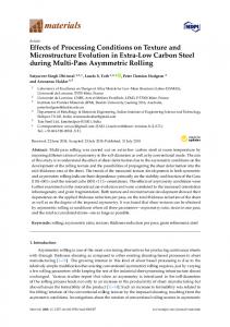
3. 3. Results Results and and Discussion Discussion 3.1. Phase Transformation and Precipitation Behavior of Carbides 3.1. Phase Transformation and Precipitation Behavior of Carbides Because the microstructure of as-cast HSS usually consists of ferrite and pearlite, austenitizing Because the microstructure of as-cast HSS usually consists of ferrite and pearlite, austenitizing and subsequent rapid cooling were employed to improve hardness of the steel. The phase stability and subsequent rapid cooling were employed to improve hardness of the steel. The phase stability diagram of AISI M42 HSS obtained from Thermo-Calc was shown in Figure 3. diagram of AISI M42 HSS obtained from Thermo-Calc was shown in Figure 3. As shown in Figure 3, the liquidus temperature and the solidus temperature of present AISI As shown in Figure 3, the liquidus temperature and the solidus temperature of present AISI M42 M42 HSS are 1680 K (1407 ◦ C) and 1500 K (1227 ◦ C), respectively. When the steel is slow cooling to HSS are 1680 K (1407 °C) and 1500 K (1227 °C), respectively. When the steel is slow cooling to room room temperature, the carbides of the present steel consisted of M6 C, M7 C3 , and MC. MC starts to temperature, the carbides of the present steel consisted of M6C, M7C3, and MC. MC starts to precipitate at 1550 K (1277 ◦ C) in the solid-liquid zone, while M6 C and M7 C3 begin to precipitate in precipitate at 1550 K (1277 °C) in the solid-liquid zone, while M6C and M7C3 begin to precipitate in the solid phase at 1500 K (1227 ◦ C) and 1140 K (867 ◦ C), respectively. That means when the specimens the solid phase at 1500 K (1227 °C) and 1140 K (867 °C), respectively. That means when the specimens are heated to the experimental temperatures and rapid cooling, M7 C3 have been dissolved into the are heated to the experimental temperatures and rapid cooling, M7C3 have been dissolved into the matrix and the carbides of the present specimens consisted of MC and M6 C. matrix and the carbides of the present specimens consisted of MC and M6C. The determined CCT diagram of AISI M42 HSS austenitized at 1473 K (1200 ◦ C) was shown in The determined CCT diagram of AISI M42 HSS austenitized at 1473 K (1200 °C) was shown in Figure 4. The dotted lines means different cooling rates range from 100 K/h to 30 K/s. The martensite Figure 4. The dotted lines means different cooling rates range from 100 K/h to 30 K/s. The martensite point (Ms ), critical temperatures of Ac1 and Ac3 (the start and end of austenitic transformation on point (Ms), critical temperatures of Ac1 and Ac3 (the start and end of austenitic transformation on heating) were determined corresponding to a heating (10 K/s) up to 1473 K (1200 ◦ C) and subsequent heating) were determined corresponding to a heating (10 K/s) up to 1473 K (1200 °C) and subsequent cooling down (5 K/s) to room temperature. As shown in Figure 4, the pearlitic transformation is only cooling down (5 K/s) to room temperature. As shown in Figure 4, the pearlitic transformation is only possible when the cooling rate is as slow as 100 K/h. Bainitic transformation occurs at the range from possible when the cooling rate is as slow as 100 K/h. Bainitic transformation occurs at the range from 100 to 1000 K/h. For the cooling rate of 1 to 30 K/s, martensite would precipitate directly and cross the 100 to 1000 K/h. For the cooling rate of 1 to 30 K/s, martensite would precipitate directly and cross area of pearlite and bainite. the area of pearlite and bainite.
Figure 3. Phase equilibrium diagram of AISI M42 HSS calculated using Thermo-Calc software. A dotted Figure 3. Phase equilibrium diagram of AISI M42 HSS calculated using Thermo-Calc software. A vertical line means the C concentration (1.11 wt. %) of the present steel. The blue lines show the region dotted vertical line means the C concentration (1.11 wt. %) of the present steel. The blue lines show of four different temperatures. the region of four different temperatures.
Metals 2017, 7, 27
5 of 13
Metals 2017, 7, 27
5 of 13
Figure 4. 4. CCT CCT diagram diagram for for AISI AISI M42 M42 HSS HSS austenitized austenitized at at 1473 1473 K K (1200 (1200 ◦°C). The dotted dotted lines lines mean mean Figure C). The different cooling rates range from 100 K/h to 30 K/s. different cooling rates range from 100 K/h to 30 K/s.
3.2. Effects Effects of of Austenitizing Austenitizing Temperature Temperatureon onMicrostructure Microstructureand andProperties Properties 3.2. SEM micrograph micrograph of of as-cast as-cast HSS HSS specimen specimen was was shown shown in in Figure Figure 5a. 5a. As SEM As indicated indicated by by arrows, arrows, network carbides M 2C, and graininess-shaped carbides MC (red circles) were found in the network carbides M2 C, and graininess-shaped carbides MC (red circles) were found in the micrograph. micrograph. 2C did not appear in the phase stability diagram because M2C particles are However, M2However, C did notMappear in the phase stability diagram because M2 C particles are in the in the metastable phase. MC carbides dispersed in the matrix and averagesize sizeofofthem them was was metastable phase. MC carbides werewere dispersed in the matrix and thethe average much smaller than M 2C carbides. The grains in the as-cast HSS were completely surrounded by the much smaller than M2 C carbides. The grains in the as-cast HSS were completely surrounded by the layers of of M M2C, namely, grain boundaries (GBs) were completely wetted by the second solid phase layers 2 C, namely, grain boundaries (GBs) were completely wetted by the second solid phase M2C carbides. Microstructure of AISI M42 HSS specimens oil cooled at different temperatures were M 2 C carbides. Microstructure of AISI M42 HSS specimens oil cooled at different temperatures were shown in Figure Figure5b–e. 5b–e.The Thepopulation populationofofthe thecarbides carbideswas wasbeing being steadily reduced with increase shown in steadily reduced with thethe increase of of temperature during austenitization. When the austenitizing temperature was 1373 K (1100 °C), ◦ temperature during austenitization. When the austenitizing temperature was 1373 K (1100 C), fibrous fibrous M2C particles decomposed into M6C and MC particles [13,14]. However, the network M 2 C particles decomposed into M6 C and MC particles [13,14]. However, the network morphology morphology of carbides exists as shown Figure With the of temperature, austenitizing of carbides still exists as still shown in Figure 5b. in With the 5b. increasing of increasing austenitizing temperature, continuous network distribution turnscattered to be broken andinscattered as the continuousthe network distribution of carbides turn toofbecarbides broken and as shown Figure 5c,d. shown in Figure 5c,d. The portion of completely wetted GBs decreased as well. When GBs wetted by The portion of completely wetted GBs decreased as well. When GBs wetted by a liquid phase (melt), a liquid phase (melt), thewetted amount of always completely wetted GBs with the increase of the amount of completely GBs increases with thealways increaseincreases of temperature due to higher temperature due to higherHowever, entropy of a melt However, when GBs wetted a second entropy of a melt [15,16]. when GBs[15,16]. are wetted by a second solidare phase, theby completely solid phase, the completely wetted GBs will decrease with the increase of temperature [17,18]. wetted GBs will decrease with the increase of temperature [17,18]. Moreover, Ms point will decrease and Moreover, M s point will decrease and the stability of austenite will increase because the highthe stability of austenite will increase because the high-temperature austenite dissolves more carbon temperature dissolves more carbon and alloying elements with the increase of austenitizing austenitizing and alloying austenite elements with the increase of austenitizing temperature [19,20]. When the temperature [19,20]. When the austenitizing temperature reaches 1473 K (1200 °C), more temperature reaches 1473 K (1200 ◦ C), more carbides dissolve into the metallic matrix so carbides that the dissolve into the metallic matrix so that the quantity of carbides reduced rapidly as shown in quantity of carbides reduced rapidly as shown in Figure 5e. No sufficient number of carbidesFigure were 5e. No sufficient number carbides were available to grain pin down the grain to prevent available to pin down the of grain boundaries to prevent coarsening, so itboundaries is more probable for grain coarsening, so it is more probable for cracks to be formed [4,9]. Besides, austenitizing cracks to be formed [4,9]. Besides, austenitizing temperature approaching the melting point of the temperature approaching the(1500 melting point to ofpartial the experimental M42 HSS (1500precipitation K) leads to experimental AISI M42 HSS K) leads melting andAISI agminate carbide partial melting and agminate carbide precipitation of the specimen. Figure 6 shows the relationship of the specimen. Figure 6 shows the relationship between the average grain size and austenitizing between the average grain size and austenitizing temperature of the specimens. The average grain size presents a smooth increase with the increase of temperature. However, it shows an impressive
Metals 2017, 7, 27
6 of 13
Metals 2017, 7, 27
6 of 13
temperature of the specimens. The average grain size presents a smooth increase with the increase of temperature. However, it shows an from impressive (35 µm) during a period from Metals 2017,(35 7, 27 6 of1453 13 in to promotion μm) during a period 1453 topromotion 1473 K. Consequently, an excessive increase 1473 K. Consequently, anincreased excessive increase in temperature resultsgrain in increased temperature results in carbide dissolution and unwanted growth. carbide dissolution promotion grain (35 μm) during a period from 1453 to 1473 K. Consequently, an excessive increase in and unwanted growth. temperature results in increased carbide dissolution and unwanted grain growth.
Figure 5. SEM microstructures ofofof the as-cast specimen (a); the oil cooling specimens Figure SEM microstructures the as-castAISI AISIM42 M42 HSS the oiloil cooling specimens at at at Figure 5. 5. SEM microstructures the as-cast AISI M42 HSS HSSspecimen specimen(a); (a); the cooling specimens 1373 K1373 (b); K (c); 1453 KK (d); and 1473 K1423 (b); 1423 (c);1453 1453 K(d); (d); and 1473KK K(e). 1373 K (b); 1423 KK(c); and 1473 (e).
Figure 6. Relationships between grain size and austenitizing temperature.
Figure Relationshipsbetween betweengrain grain size size and austenitizing Figure 6. 6. Relationships austenitizingtemperature. temperature.
Metals 2017, 7, 27
7 of 13
Table 2 presents the corresponding hardness and impact toughness of AISI M42 HSS specimens with different austenitizing temperatures and holding time. The hardness increased with the austenitizing temperature between 1373 and 1453 K, but decreased when the austenitizing temperature reached 1473 K. This phenomenon could be explained by the reducing of well-distribution hard carbides. The hardness of quenched HSS is affected by the microstructure, the quantity of carbides, and alloy elements in the martensite and the retained austenite [21,22]. Carbon and alloying elements dissolved into the austenite, and then transferred to martensite by oil cooling, and the quantity increased with the increase of austenitizing temperature. However, when the austenitizing temperature reached 1473 K, there was an excess dissolution of carbon and alloying elements in the austenite. Besides, Ms tends to decrease when alloying elements dissolved in the steel at high temperature [21]. It lead to excess retained austenite remaining in the microstructure after oil cooling which reduced the hardness of the steel. On the contrary, the impact toughness increased with the increase of austenitizing temperature for the increasing of retained austenite. Consequently, in the experimental temperature range, the tendency of the hardness of the specimens presented a peak, and the impact toughness increased with increasing temperature. Table 2. Effects of austenitizing conditions on hardness and impact toughness of AISI M42 HSS. Austenitizing Temp. (K)
Holding Time (min)
Hardness (HRc)
Impact Toughness (J)
1373 1423 1453 1453 1453 1473
15 15 15 30 45 15
58.5 59.8 65.5 65.7 64.8 63.7
8.7 10.4 10.9 11.2 11.9 12.5
3.3. Effects of Austenitizing Time on Microstructure and Properties The series in Figure 7 represent SEM micrographs of the specimens austenitized at 1453 K for 15 to 45 min. From Figure 7a,b, change on the microstructure of the specimens was not obvious under the austenitizing time ranges between 15 and 30 min, as well as the hardness (Table 2). However, the hardness of the specimen decreased when the holding time up to 45 min. Besides, the average size of the carbides tends to increase but the quantity of carbides seems decrease as shown in Figure 7c. This phenomenon could be explained by the fact of Ostwald ripening. Since carbides with large sizes have a lower interfacial concentration. The resulting concentration gradients give rise to diffusional transport from small carbides to the matrix then to large carbides. Thus, large carbides tend to grow at the expense of the small carbides, the average particle size increases, and the total number of carbides decreases [23,24]. The impact toughness of the specimens increased with the increase of holding time. Because more carbides and alloy elements dissolved in the matrix promoted solution strengthening, and made retained austenite stable. Figure 8 is the volume fraction of carbides in the specimens with different holding time and austenitizing temperatures. The blue line means cooling at different austenitizing temperature but with the same holding time—i.e., 15 min. The red line represents cooling with different holding time at the same austenitizing temperature, i.e., 1453 K. Compared with that of the as-cast specimen, the quantity of carbides in AISI M42 HSS after austenitizing reduced greatly. At 1453 K, the quantity of carbides showed a smooth decrease with the increase of holding time. It could be thought that this decrease in the amount of the carbides is due to the dissolution of carbides into austenite matrix phase. Moreover, the decrease of carbides with different holding time is much weaker than that with different austenitizing temperatures. Consequently, the effect of austenitizing temperature on the microstructure and hardness of AISI M42 HSS is more influential than the austenitizing time.
Metals 2017, 7, 27 Metals 2017, 7, 27 Metals 2017, 7, 27
8 of 13 8 of 13 8 of 13
Figure 7. Microstructures of the oil oil cooling AISI M42 HSS specimens at K 15 min(a); (a); 30min min (b); Figure 7. Microstructures the cooling AISI M42 at 1453 1453 K for for Figure 7. Microstructures ofofthe oil cooling AISI M42HSS HSSspecimens specimens at 1453 K 15 formin 15 min30 (a); 30 min and 45 min (c). 45 min (b); (b); andand 45 min (c).(c).
Figure 8. The volume in the the specimens specimenswith with different holding Figure 8. The volumefraction fraction of of carbides carbides in different holding time time and and austenitizing temperatures. austenitizing temperatures. Figure 8. ofThe volume fraction of carbides in the specimens with different holding time and 3.4. Effects Cooling Rate on Microstructure and Properties 3.4. Effects of Cooling Rate on Microstructure and Properties austenitizing temperatures. In order to investigate the effects of cooling rate on the microstructure and observe the phase
In order to investigate the effects of cooling rate on the microstructure and observe the phase transformation and precipitation of AISI M42 HSS in situ, CSLM was employed in combination with 3.4. Effects of Cooling Rate on Microstructure andHSS Properties transformation and precipitation of determination. AISI M42 situ, CSLM was employed in combination with thermal dilatometer experimental Min s and Mf were measured by a thermal dilatometer thermal dilatometer experimental determination. M and measured byand a thermal s f were and shownto in investigate Figure 9. In order the effects of cooling rate onMthe microstructure observedilatometer the phase and shown in Figure 9. transformation and precipitation of AISI M42 HSS in situ, CSLM was employed in combination with thermal dilatometer experimental determination. Ms and Mf were measured by a thermal dilatometer and shown in Figure 9.
Metals 2017, 7, 27
9 of 13
Metals 2017, 7, 27
9 of 13
Figure s and f of as-castAISI AISI M42 M42 HSS cooling rates. Figure 9. M9.s M and MfMof as-cast HSSunder underdifferent different cooling rates.
As the cooling rate increases, the value of the Ms and Mf points decrease consequently (Figure
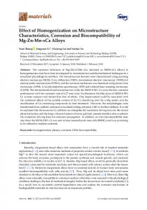
As the cooling rate increases, the value of the M and M points decrease consequently (Figure 9). 9). When the cooling rate is 5 K/s, the value of Mssand Mf fare 448 K (175 °C) and 380 K (107 °C), Whenrespectively. the coolingWhen ratethe is 5cooling K/s, rate the reaches value of Mf are K (175 ◦ C) and 380 K (107 ◦ C), s and 20 M K/s, the value of M448 s and Mf decrease to 419 K (146 °C) respectively. When therespectively. cooling rate reaches 20 K/s, the value of Ms and Mf decrease to 419 K (146 ◦ C) and 347 K (74 °C), ◦ and 347 KFigure (74 C), 10 respectively. shows the sequential image of the in-situ observation on AISI M42 HSS cooling from 1473 K 10 (1200 °C) tothe room temperature by the rate in-situ of 5 K/s.observation Each image is in the order of thefrom Figure shows sequential image of the onarranged AISI M42 HSS cooling ◦ corresponding temperature. Figure 10a,b is magnified 500 times and Figure 10c–f is magnified 1473 K (1200 C) to room temperature by the rate of 5 K/s. Each image is arranged in the 1000 order of times. In the heat up stage, some small carbides precipitated of the volume contraction the corresponding temperature. Figure 10a,b is magnified 500 because times and Figure 10c–f is magnified caused by austenite transformation (Figure 10a). When the temperature reached 1473 K (1200 °C), an 1000 times. In the heat up stage, some small carbides precipitated because of the volume contraction outburst of precipitation and growth of carbides appeared (Figure 10b). At the beginning of cooling, ◦ caused by austenite transformation (Figure 10a). When the temperature reached 1473 K (1200 C), the specimen consisted of austenite and carbides which precipitate on the grain boundaries, and the an outburst of precipitation and growth of carbides appeared (Figure 10b). At the beginning of cooling, grain size was about 15 to 25 μm (Figure 10c). When the temperature decreased to 1281 K (1008 °C), the specimen consisted of austenite andfrom carbides which precipitate on the grain boundaries, and the acicular ferrite started to transform austenite (Figure 10d). The martensitic transformation grainbegan size was about 15Kto(173 25 °C) µmwith (Figure 10c). When temperature decreased K (1008 ◦ C), at about 446 a saltatory mode the along the grain boundary and to the1281 undissolved acicular ferriteas started austenite (Figure The martensitic began carbides, showntointransform Figure 10e.from During the increase of 10d). marensite, a position oftransformation grain boundaries ◦ were replaced by martensite. No pearlite appears in the range from 1281 K (1008 °C) to 446 K (173 °C), at about 446 K (173 C) with a saltatory mode along the grain boundary and the undissolved carbides, which thatDuring the cooling rate of 5ofK/s is greatera position than the of critical rate ofwere pearlitic as shown in indicates Figure 10e. the increase marensite, graincooling boundaries replaced ◦ C) ◦ C), which transformation (Figure 4). When in thethe temperature room temperature, martensitic by martensite. No pearlite appears range fromdropped 1281 K to (1008 to 446 K (173 transformation was still underway and there was a small group of retained austenite in the indicates that the cooling rate of 5 K/s is greater than the critical cooling rate of pearlitic transformation microstructure (Figure 10f). It is worth noting that martensitic transformation is usually finished rapidly (Figure 4). When the temperature dropped to room temperature, martensitic transformation was in most of low-carbon steels [25,26]. However, for the high-carbon steel AISI M42, martensite transformed still underway and there a small still group of retained austenite in the microstructure (Figure with a saltatory mode.was Martensite emerged sporadically during in-situ observation when the 10f). It is worth noting that martensitic transformation is usually finished rapidly in most of low-carbon temperature dropped to room temperature. Because martensitic transformation is affected by shear steelsresistance [25,26]. However, the high-carbon steel AISI martensite a saltatory in kinetics, for it could be worth considering thatM42, a higher content oftransformed carbon wouldwith increase the mode.shear Martensite still during in-situ observation when the temperature dropped resistance of emerged martensiticsporadically transformation and slow down the transformation rate. to room temperature. Because martensitic transformation is affected by shear resistance in kinetics, it could be worth considering that a higher content of carbon would increase the shear resistance of martensitic transformation and slow down the transformation rate.
Metals 2017, 7, 27
Metals 2017, 7, 27
10 of 13
10 of 13
Figure 10. In-situ observation of phase transformation during austenitizing process of AISI M42 HSS Figure 10. In-situ observation of phase transformation during austenitizing process of AISI M42 HSS with the cooling rate of 5 K/s: (a) 1423 K (×500); (b) 1473 K (×500); (c) 1473 K (×1000); (d) 1281 K with the cooling rate of 5 K/s: (a) 1423 K (×500); (b) 1473 K (×500); (c) 1473 K (×1000); (d) 1281 K (×1000); (×1000); (e)K446 K (×(f) 1000); room temperature (e) 446 (×1000); room(f)temperature (×1000). (×1000).
phase transformationand andprecipitation precipitation behavior M42 HSS austenitizing at 1473 K The The phase transformation behaviorofofAISI AISI M42 HSS austenitizing at 1473 K (1200 °C) with the cooling rate of 20 K/s was shown in Figure 11. It seems to be very different from ◦ (1200 C) with the cooling rate of 20 K/s was shown in Figure 11. It seems to be very different that with the cooling rate of 5 K/s. At the beginning of cooling, the specimen also consisted of from that with the cooling rate of 5 K/s. At the beginning of cooling, the specimen also consisted of austenite and carbides (Figure 11a). Acicular and triangular ferrite transformation began at 1323 K austenite and carbides (Figure 11a). Acicular and triangular ferrite transformation began at 1323 K (1050 °C) (Figure 11b). The grain size was uneven between 20 and 50 μm. Because the cooling rate ◦ C) (Figure 11b). The grain size was uneven between 20 and 50 µm. Because the cooling rate (1050(20 K/s) is much greater than the critical cooling rate of pearlitic transformation, no pearlite appeared (20 K/s) is process much greater than(Figure the critical cooling rate of pearlitic transformation, no°C), pearlite appeared in the of cooling 4). When the temperature decreased to 421 K (148 martensite ◦ C), martensite in thestarted process of cooling (Figure 4). When the temperature decreased to 421 K (148 to transform from the austenite (Figure 11c). Because there was so little time for martensitic transformation and carbide there was stillBecause much retained that time had not started to transform from the dissolution, austenite (Figure 11c). there austenite was so little forfinished martensitic the transformation in thedissolution, microstructure (Figure 11d). Moreover, increasing the cooling ratefinished could the transformation and carbide there was still much retained austenite that had not decrease M s and Mf point which narrow the martensitic transformation range (Figure 9). The carbides transformation in the microstructure (Figure 11d). Moreover, increasing the cooling rate could decrease likewise werewhich hardly dissolved and presented network, which could provide routes for crack Ms and Mf point narrow the martensitic transformation range (Figure 9). The carbides likewise propagation and make cracks deeper [27,28]. Therefore, it might be worth considering that a high were hardly dissolved and presented network, which could provide routes for crack propagation and make cracks deeper [27,28]. Therefore, it might be worth considering that a high cooling rate can depress the martensitic transformation and increase the content of retained austenite. Consequently,
Metals 2017, 7, 27 Metals 2017, 7, 27
11 of 13 11 of 13
cooling rate can depress the martensitic transformation and better increase the content of retained austenite. an exorbitant cooling rate prevents less retained austenite, microstructure, and higher hardness Consequently, in AISI M42 HSS. an exorbitant cooling rate prevents less retained austenite, better microstructure, and higher hardness in AISI M42 HSS.
Figure In-situ observation of during austenitizing processprocess of AISI M42 HSS M42 Figure 11. 11. In-situ observation of phase phasetransformation transformation during austenitizing of AISI raterate of 20 (a) 1473 (×1000); (b) 1323 K (c)(× 421 K (×1000); (d)Kroom HSS with withthe thecooling cooling of K/s: 20 K/s: (a)K1473 K (× 1000); (b)(×1000); 1323 K 1000); (c) 421 (×1000); temperature (×1000). (d) room temperature (×1000).
4. Conclusions
4. Conclusions
In this study, effects of austenitizing temperature, holding time, and cooling rate on the In this study,and effects of austenitizing temperature, holding time, and have cooling on the microstructure hardness of AISI M42 HSS were investigated. The conclusions beenrate drawn microstructure and hardness of AISI M42 HSS were investigated. The conclusions have been drawn as follows:
as follows: 1.
1.
2.
3.
When the austenitizing temperature is 1373 K, the network morphology of carbides could not dissolve completely and distribute equably. When the austenitizing temperature reaches 1473 When the austenitizing temperature is 1373 K, the network morphology of carbides could not K, the excessive increase in temperature leads to increased carbide dissolution and unwanted dissolve completely and distribute equably. When the austenitizing temperature reaches 1473 K, grain growth. 1453 K gives the best austenitizing condition on temperature for AISI M42 HSS. the excessive increase in temperature leads increased carbide dissolution andbetween unwanted 2. The amount of hardness increases with the to increase of austenitizing temperature 1373grain growth. 1453K,Kbut gives the best austenitizing condition on temperature for K. AISI HSS. of and 1453 decreases when the austenitizing temperature reaches 1473 TheM42 hardness The the amount of hardness increases withmuch the increase of holding austenitizing AISI M42 HSS does not change when the time istemperature less than 30 between min, but 1373 when the holding 45 mintemperature because of Ostwald The hardness impact and decreases 1453 K, but decreases whentime the reaches austenitizing reachesripening. 1473 K. The of toughness of thedoes specimens increases with the increase of austenitizing temperature andbut holding the AISI M42 HSS not change much when the holding time is less than 30 min, decreases time. when the holding time reaches 45 min because of Ostwald ripening. The impact toughness of the 3. The value of Ms and Mf decrease with the increase of cooling rate. High cooling rate can depress specimens increases with the increase of austenitizing temperature and holding time. the martensitic transformation and increase the content of retained austenite, which prevents The less value of M and Mf decrease with the increase of cooling rate. High cooling rate can depress retaineds austenite, better microstructure, and higher hardness in AISI M42 HSS.
the martensitic transformation and increase the content of retained austenite, which prevents less
Acknowledgments: Thisbetter study was financially supported by the National Natural Science Foundation retained austenite, microstructure, and higher hardness in AISI M42 HSS. of China (NSFC) by a Grant of No. U1560203 and No. 51274031. Author Contributions: Yiwa Luo and Hanjie Guo conceived and designed the experiments; Mingtao Mao and
Acknowledgments: This study was financially supported by the National Natural Science Foundation of China Jing Guo performed the experiments; Yiwa Luo and Xiaolin Sun analyzed the data; Xiaolin Sun contributed (NSFC) by a Grant of No. U1560203 and No. 51274031. analysis tools; Yiwa Luo wrote the paper.
Author Contributions: Yiwa Luo and Hanjie Guo conceived and designed the experiments; Mingtao Mao and Conflicts of Interest: authors declare conflict interest.Sun analyzed the data; Xiaolin Sun contributed Jing Guo performed the The experiments; YiwanoLuo andofXiaolin analysis tools; Yiwa Luo wrote the paper. Conflicts of Interest: The authors declare no conflict of interest.
Metals 2017, 7, 27
12 of 13
References 1.
2. 3. 4. 5.
6. 7. 8. 9. 10. 11. 12. 13. 14. 15.
16. 17. 18. 19. 20. 21. 22. 23. 24.
Kim, C.K.; Park, J.I.; Lee, S.; Kim, Y.C.; Kim, N.J.; Yang, J.S. Effects of alloying elements on microstructure, hardness, and fracture toughness of centrifugally cast high-speed steel rolls. Metall. Mater. Trans. A 2005, 36, 87–97. [CrossRef] Sano, Y.; Hattori, T.; Haga, M. Characteristics of high-carbon high speed steel rolls for hot strip mill. ISIJ Int. 1992, 32, 1194–1201. [CrossRef] Zhou, X.F.; Fang, F.; Li, F.; Jiang, J.Q. Morphology and microstructure of M2 C carbide formed at different cooling rates in AISI M2 high speed steel. J. Mater. Sci. 2011, 46, 1196–1202. [CrossRef] Yu, T.H.; Yang, J.R. Effect of retained austenite on GPM A30 high-speed steel. J. Mater. Eng. Perform. 2007, 16, 500–507. [CrossRef] Cambronero, L.E.G.; Gordo, E.; Torralba, J.M.; Ruiz-Prieto, J.M. Comparative study of high speed steels obtained through explosive compaction and hot isostatic pressing. Mater. Sci. Eng. A 1996, 207, 36–45. [CrossRef] Xu, L.; Xing, J.; Wei, S.; Chen, H.; Long, R. Comparative investigation to rolling wear properties between high-vanadium high-speed steel and high-chromium cast iron. J. Xi’an Jiaotong Univ. 2006, 40, 275–278. Himuro, Y.; Kainuma, R.; Ishida, K. Martensitic transformation and shape memory effect in ausaged Fe-Ni-Si alloys. ISIJ Int. 2002, 42, 184–190. [CrossRef] Durlu, T.N. Effects of high austenitizing temperature and austenite deformation on formation of martensite in Fe-Ni-C alloys. J. Mater. Sci. 2001, 36, 5665–5671. [CrossRef] Sarafianos, N. The effect of the austenitizing heat-treatment variables on the fracture toughness of high-speed steel. Metall. Mater. Trans. A 1997, 28, 2089–2099. [CrossRef] Hashimoto, M.; Kubo, O.; Matsubara, Y. Analysis of carbides in multi-component white cast iron for hot rolling mill rolls. ISIJ Int. 2004, 44, 372–380. [CrossRef] Fu, H.; Qu, Y.; Xing, J.; Zhi, X.; Jiang, Z.; Li, M.; Zhang, Y. Investigations on heat treatment of a high-speed steel roll. J. Mater. Eng. Perform. 2008, 17, 535–542. [CrossRef] Kang, M.; Lee, Y.K. The effects of austenitizing conditions on the microstructure and wear resistance of a centrifugally cast high-speed steel roll. Metall. Mater. Trans. A 2016, 47, 3365–3374. [CrossRef] Zhou, X.; Fang, F.; Li, G.; Jiang, J. Morphology and properties of M2 C eutectic carbides in AISI M2 steel. ISIJ Int. 2010, 50, 1151–1157. [CrossRef] Hwang, K.C.; Lee, S.; Lee, H.C. Effects of alloying elements on microstructure and fracture properties of cast high speed steel rolls part I: Microstructural analysis. Mater. Sci. Eng. A 1998, 254, 282–295. [CrossRef] Straumal, B.B.; Kucheev, Y.O.; Efron, L.I.; Petelin, A.L.; Majumdar, J.D.; Manna, I. Complete and incomplete wetting of ferrite grain boundaries by austenite in the low-alloyed ferritic steel. J. Mater. Eng. Perform. 2012, 21, 667–670. [CrossRef] Modica, L. Critical point wetting. J. Chem. Phys. 1977, 66, 359–361. Straumal, B.B.; Baretzky, B.; Kogtenkova, O.A.; Straumal, A.B.; Sidorenko, A.S. Wetting of grain boundaries in Al by the solid Al3 Mg2 phase. J. Mater. Sci. 2010, 45, 2057–2061. [CrossRef] Straumal, B.B.; Gornakova, A.S.; Kucheev, Y.O.; Baretzky, B.; Nekrasov, A.N. Grain boundary wetting by a second solid phase in the Zr-Nb alloys. J. Mater. Eng. Perform. 2012, 21, 721–724. [CrossRef] Zhou, B.; Shen, Y.; Chen, J.; Cui, Z.S. Evolving mechanism of eutectic carbide in as-cast AISI M2 high-speed steel at elevated temperature. J. Shanghai Jiaotong Univ. Sci. 2010, 15, 463–471. [CrossRef] Deng, Y.K.; Chen, J.R.; Wang, S.Z. High Speed Tool Steel; Guo, G.C., Ed.; Metallurgical Industry Press: Beijing, China, 2002; pp. 199–200. Yamamoto, K.; Kogin, T.; Harakawa, T.; Murai, N.; Kuwano, M.; Ogi, K. Effects of alloying elements in hardenability for high C high speed steel type alloy. J. Jpn. Foundry Eng. Soc. 2000, 72, 90–95. Barlow, L.D.; Toit, M.D. Effect of austenitizing heat treatment on the microstructure and hardness of martensitic stainless steel AISI 420. J. Mater. Eng. Perform. 2012, 21, 1327–1336. [CrossRef] Snyder, V.A.; Akaiwa, N.; Alkemper, J.; Voorhees, P.W. The influence of temperature gradients on Ostwald ripening. Metall. Mater. Trans. A 1999, 30, 2341–2348. [CrossRef] Garay-Reyes, C.G.; Hernandez-Santiago, F.; Cayetano-Castro, N.; Martinez-Sanchez, R.; Hernandez-Rivera, J.L.; Dorantes-Rosales, H.J.; Cruz-Rivera, J. Analysis of Ostwald ripening in Ni-rich Ni-Ti alloys by diffusion couples. J. Bull. Mater. Sci. 2014, 37, 823–829. [CrossRef]
Metals 2017, 7, 27
25.
26. 27.
28.
13 of 13
Alvarado-Meza, M.A.; Garcia-Sanchez, E.; Covarrubias-Alvarado, O.; Salinas-Rodriguez, A.; Guerrero-Mata, M.P.; Colas, R. Effect of the high-temperature deformation on the Ms temperature in a low C martensitic stainless steel. J. Mater. Eng. Perform. 2013, 22, 345–350. [CrossRef] Morito, S.; Yoshida, H.; Maki, T.; Huang, X. Effect of block size on the strength of lath martensite in low carbon steels. Mater. Sci. Eng. A 2006, 438–440, 237–240. [CrossRef] Nogueira, R.A.; Riberiro, O.C.S.; Das-Neves, M.D.M.; de Lima, L.F.C.P.; Filho, F.A.; Friedrich, D.N.; Boehs, L. Influence of the heat treatment on the microstructure of AISI T15 high speed steel. Mater. Sci. Forum 2003, 416–418, 89–94. [CrossRef] Hwang, K.C.; Lee, S.; Lee, H.C. Effects of alloying elements on microstructure and fracture properties of cast high speed steel rolls part II: Fracture behavior. Mater. Sci. Eng. A 1998, 254, 296–304. [CrossRef] © 2017 by the authors; licensee MDPI, Basel, Switzerland. This article is an open access article distributed under the terms and conditions of the Creative Commons Attribution (CC-BY) license (http://creativecommons.org/licenses/by/4.0/).