materials Article
Effect of Homogenization on Microstructure Characteristics, Corrosion and Biocompatibility of Mg-Zn-Mn-xCa Alloys Yuan Zhang
ID
, Jingyuan Li *, Huiying Lai and Yuzhao Xu
School of Materials Science and Engineering, University of Science and Technology Beijing (USTB), Beijing 100083, China;
[email protected] (Y.Z.);
[email protected] (H.L.);
[email protected] (Y.X.) * Correspondence:
[email protected]; Tel.: +86-010-8237-6939 Received: 23 December 2017; Accepted: 31 January 2018; Published: 1 February 2018
Abstract: The corrosion behaviors of Mg-2Zn-0.2Mn-xCa (denoted as MZM-xCa alloys) in homogenization state have been investigated by immersion test and electrochemical techniques in a simulated physiological condition. The microstructure features were characterized using scanning electron microscopy (SEM), X-ray diffraction (XRD), transmission electron microscopy (TEM) and electron probe microanalysis (EPMA), and the corrosion mechanism was illustrated using atomic force microscope (AFM), X-ray photoelectron spectroscopy (XPS) and confocal laser scanning microscopy (CLSM). The electrochemical and immersion test verify the MZM-0.38% Ca owns the best corrosion performance with the corrosion rate of 6.27 mm/year. Furthermore, the film layer of MZM-0.38% Ca is more compact and denser than that of others. This improvement could be associated with the combined effects of the suitable content of Zn/Ca dissolving into the α-Mg matrix and the modification of Ca-containing compounds by heat-treatment. However, the morphologies were transformed from uniform corrosion to localized pitting corrosion with Ca further addition. It could be explained that the excessive Ca addition can strengthen the nucleation driving force for the second phase formation, and the large volumes fraction of micro-galvanic present interface sites accelerate the nucleation driving force for corrosion propagation. In addition, in vitro biocompatibility tests also show the MZM-0.38% Ca was safe to bone mesenchymal stem cells (BMSCs) and was promising to be utilized as implant materials. Keywords: homogenization; phases; corrosion; TEM; biocompatibility
1. Introduction Recently, magnesium-based alloys and composites have a crucial role in implant materials applications [1–6], due to the moderate mechanical properties similar to bone tissue [7–12]. In addition, Mg2+ is also the second most important cation for special physiological functions, which can activate the body enzymes, participate in the protein synthesis and muscle growth, and maintain the structure stability of nucleic acid [13]. Besides, Mg-based alloys could be gradually dissolved, absorbed, consumed by metabolic reactions, and then excreted with urinary system after the tissues heal [7,13,14]. Moreover, magnesium alloys have no systemic toxicity in human body and possess excellent biocompatibility with cells activity [15]. Thus, Mg and its alloys have been paid more attention to develop as the candidate biomaterials for clinical applications [1,2,6]. However, these Mg alloys were extremely susceptible to corrosion medium when they were exposed to the physiological condition, leading to the loss of mechanical integrity before the tissues have recovered completely [3]. As a result, how to accurately control degradation rate and explore the corrosion mechanism of biodegradable materials in vitro has become an important problem.
Materials 2018, 11, 227; doi:10.3390/ma11020227
www.mdpi.com/journal/materials
Materials 2018, 11, 227
2 of 17
Some efforts have been paid to enhance the corrosion resistance and explore the corrosion mechanism of implant materials [16–18]. Unfortunately, almost all these Mg-based alloys consist of aluminum, nickel or other rare earth elements [2,6,9,12,16–22]. The permanent presence of these elements in the physiological environment may induce latent toxicity and gradually cause chronic diseases (Alzheimer’s disease and muscle fiber damage) [13,23–27]. Therefore, it is essential to develop an adequate degradable alloy. Moreover, the degradation behavior of implant materials depends not only on the type and concentrations of alloying elements but also on the microstructure (grain size and phases distribution) features of the alloys with treatment (temperature, plastic working, and surface modification). Among all of the methods, alloying is an effective means not only for enhancing corrosion resistance with microstructure modification but also endowing the degradable materials with moderate mechanical properties by tailoring the phase morphology, distribution, potential, and size of the matrix [28–30]. Besides, the correlations of phase characteristics and degradation behaviors of Mg-xZn (x = 2, 3, 4, 5, 6) alloys were also studied in the simulated body fluid [1,31–34]. Bakhsheshi-Rad et al. [35–37] further discussed that the corrosion behavior of Mg-0.5Ca-xZn (x = 0, 0.5, 1, 3, 4, 5, 6, 9) and Mg-2Ca-0.5Mn-xZn (x = 2, 4, 7) were improved with Zn concentration addition, whereas it would produce a reversed effect with the Zn further addition. Cho et al. [38] also demonstrated that the Mn addition was beneficial to improve the degradation performance of Mg-4Zn-0.5Ca alloy, where the dense film layers of MnO and MnO2 on the surface can inhibit the chloride ion permeation and control matrix dissolution. In addition, the β-Ca3 (PO4 )2 addition in Mg-Zn series alloys were further investigated [39,40]. These results showed that adding β-Ca3 (PO4 )2 could strengthen the mechanical properties and corrosion resistance via hot extrusion and aging treatment. Based on the above, there is very limited research related to the degradation behavior of Mg-2Zn-0.2Mn-xCa alloys with homogenization treatment in the Kokubo solution. Thus far, the mechanism of phase characteristics (surface Volta potential distribution and interface distinction) on the corrosion resistances of Mg-2Zn-0.2Mn-xCa and 3D corrosion profiles in the Kokubo solution have not been discussed, and the data about biocompatibility of investigated alloys are relatively scarce. Therefore, in this study, the comprehensive microstructure observation of MZM-xCa alloys subjected to homogenization treatment were investigated by TEM, SEM, EPMA, XRD, XPS and AFM, and their in vitro biocompatibility was also examined. Furthermore, the degradation mechanism is further illustrated. 2. Experimental Details 2.1. Preparation of the Alloys The Mg-Zn-Mn-xCa (MZM-xCa) alloys were prepared from high-purity Mg (>99.94%), high-purity Zinc (99.99%), Mg-Ca (20% wt %) and Mg-Mn (5% wt %) master alloys. The melts were held at 750 ◦ C for 20 min under the gas mixture of Ar/SF6 . Then, the melts were poured into a graphite crucible and cooled at ambient temperature. Before casting, the graphite mold was preheated at 250 ◦ C. The composition analysis was determined by ICP-AES (Varian 715-ES), and the results are listed in Table 1. Afterwards, all billets were subjected to homogenization treatment at 380 ◦ C for 24 h and then cooled by water. Table 1. Chemical composition of the experimental alloys (wt %). Experimental Alloys
Zn
Ca
Mn
Mg
MZM MZM-0.38 Ca MZM-0.76 Ca MZM-1.10 Ca
2.12 2.08 2.11 2.08
/ 0.38 0.76 1.10
0.20 0.20 0.20 0.20
Bal. Bal. Bal. Bal.
Materials 2018, 11, 227
3 of 17
2.2. Microstructure Characterization Samples for microstructure observation were polished down to 0.25 µm, and then were etched using 5 g picric acid, 10 mL acetic acid (17.5 mol/L), 10 mL distilled water and 100 mL ethanol. Then, the microstructure characteristics were detected using SEM (Zeiss Auriga, Oberkochen, Germany) and EPMA (JXA-8100, JEOL, Akishima, Japan). The phases characteristics were detected using XRD (SmartLab) (Rigaku Co., Ltd., Tokyo, Japan) and TEM (Tecnai G2) (Thermo Fisher Scientific, Hillsboro, OR, USA). The surface Volta potential distributions and corrosion profile were detected using AFM (MFP 3D Infinity, Oxford Instrument, Abingdon, UK), which was conducted at 25 ◦ C and a relative humidity of 40 ± 5% [41]. 2.3. Electrochemical Measurement According to ASTM G3-89 [42], the polarization measurements were measured in the Kokubo solution using an electrochemical workstation (Princeton Versa STAT 3F, AMETEK, Chicago, IL, USA). The standard three-electrode system consists of a saturated calomel electrode as the reference electrode, a platinum plate as the counter electrode and the as-prepared sample with an exposed area of 1 cm2 as the working electrode. The composition of Kokubo solution is listed in Table 2. When the open circuit potential (OCP) reaches the steady-state for 30 min, the measurement was conducted with a scan rate of 1 mV/s. The corrosion potentials (Ecorr , VSCE ) and corrosion current densities (Icorr , mA/cm2 ) were calculated from the polarization curves by the Tafel extrapolation method. The corrosion rate (Pi , mm/year) was related to corrosion current densities, according to the following equation [35]: Pi = 22.85 Icorr
(1)
Table 2. Ion concentrations of Blood plasma and simulated body fluid [26,43]. Solution SBF Blood Plasma
Concentrations (mM) Na+
K+
Mg2+
Ca2+
Cl−
HCO3−
HPO4 2−
SO4 2−
142 142
5.0 5.0
1.5 1.5
2.5 2.1–2.6
147.8 95–107
4.20 27
1.0 0.7–1.5
0.5 0.5
Buffer Tris -
2.4. Immersion Test In accordance with ASTM G31-72 [44], the immersion test was conducted in the Kokubo solution at 37 ◦ C for 240 h, and the ratio of specimen surface area to solution volume was 1:30 cm2 /mL. Prior to immersion tests, all samples were polished down to 0.25 µm and weighted. After the immersion test, the corrosion products were analyzed by SEM, XPS and XRD, respectively. Subsequently, according to the G1-03 (2011), the corrosion products were chemically removed using a solution containing 200 g/L CrO3 and 10 g/L AgNO3 , and then the corrosion morphologies were characterized by confocal laser scanning microscopy (CLSM) (OLS 4000, Olympus, Tokyo, Japan). The corrosion rate (CR) was determined using the following equation: CR =
K×W A×T×D
(2)
where K is a constant (8.76 × 10⁴ for rate unit of millimeter per year), W is mass loss (g), A is the sample area exposed to solution (cm2 ), T is the time of exposed (h) and D is the density of materials (g·cm3 ). Each specimen was tested three times under the identical conditions. 2.5. In Vitro Biocompatibility Assessment Human bone marrow mesenchymal stem cells were adopted to evaluate the cytotoxicity of the investigated MZM-xCa alloys. The BMSCs were cultured in Dulbecco’s modified Eagle’s medium (DMEM, Gibco, Waltham, MA USA) supplemented with 10% fetal bovine serum (FBS, Gibco, Waltham, MA USA), 100 units/mL penicillin and 100 units/mL streptomycin in a cell incubator (humidified
Materials 2018, 11, 227
4 of 17
atmosphere with 5% CO2 at 37 ◦ C). The cytotoxicity tests were carried out by indirect contact. Polished samples were washed, dried in air and sterilized via Co60 γ ray radiation. Extracts were prepared using DMEM serum free medium as the extraction medium with the surface area to extraction medium ratio 1.25 mL/cm2 in a humidified atmosphere with 5% CO2 at 37 ◦ C for 72 h, according to ISO 10993-5:1999. The supernatant fluid was withdrawn and filtered Materials 2018, 11, x FOR PEER REVIEW 4 of 17 to prepare the extraction medium, and subsequently preserved at 4 ◦ C before the cytotoxicity test. The control groups involved the use of DMEM medium as negative controls. The BMSCs were (humidified atmosphere with 5% CO2 at 37 °C). The cytotoxicity tests were carried out by indirect seeded incontact. 96-well plates at a density of 5000 cells/well and incubated for h to allow attachment. Polished samples were washed, dried in air and sterilized via Co60 γ ray24 radiation. Extracts were serum free medium as themedium, extraction medium with the for 1, 2 Then, the medium was prepared replacedusing withDMEM 100 µL extract or DMEM and incubated surface area to extraction medium ratio 1.25 mL/cm2 in a humidified atmosphere with 5% CO2 at 37 and 3 days, respectively. In addition, the relative growth rate (RGR) was calculated for all samples °C for 72 h, according to ISO 10993-5:1999. The supernatant fluid was withdrawn and filtered to using theprepare Cell Counting Kit-8 (CCK-8, Sigma-Aldrich, St. Louis, MO, USA). After each assay time the extraction medium, and subsequently preserved at 4 °C before the cytotoxicity test. The point, 10control µL CCK-8 solution wasuse added to each well and then it wasThe incubated forseeded 2 h. The groups involved the of DMEM medium as negative controls. BMSCs were in optical 96-well plates at a density of 5000 cells/well and incubated for 24ahmicroplate to allow attachment. Then, the Bio-Rad, density (OD) was measured at the wavelength of 450 nm using reader (iMARK, was replaced with 100 μL extract DMEM medium, and incubated forrate 1, 2 (RGR) and 3 days, Hercules,medium CA, USA). The cell viabilities wereorexpressed as relative growth determined respectively. In addition, the relative growth rate (RGR) was calculated for all samples using the Cell by RGR (%) = {(OD)sample/OD (negative control)} × 100%. All the data were presented as the mean Counting Kit-8 (CCK-8, Sigma-Aldrich, St. Louis, MO, USA). After each assay time point, 10 μL CCKRGR value ± standard deviation. Statistical analysis was conducted tooptical evaluate the(OD) difference in cell 8 solution was added to each well and then it was incubated for 2 h. The density was viability by analysis of wavelength variance (ANOVA), where the statistical wasHercules, definedCA, as p < 0.05. measured at the of 450 nm using a microplate reader significance (iMARK, Bio-Rad, USA). The cell viabilities were expressed as relative growth rate (RGR) determined by RGR (%) = {(OD)sample/OD (negative control)} × 100%. All the data were presented as the mean RGR value ± 3. Results and Discussion
3.1.
standard deviation. Statistical analysis was conducted to evaluate the difference in cell viability by analysis of variance (ANOVA), where the statistical significance was defined as p < 0.05. Microstructure Characteristics
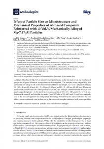
3. Results and Discussion Figure 1 reveals the microstructure evolution of as-homogenized MZM-xCa alloys with various Ca content addition. The grain size within Mg-2Zn-0.2Mn (Figure 1a) alloy was remarkably 3.1. Microstructure Characteristics inhomogeneous, for which the smallest grain size was less than 40–50 µm and the largest size was Figure reveals thethe microstructure of as-homogenized MZM-xCa alloys gain with various more than 400 µm.1 Besides, MZM hasevolution the equiaxed grains, and the average size was about Ca content addition. The grain size within Mg-2Zn-0.2Mn (Figure 1a) alloy was remarkably 180 µm by the linear intercept methods. The grain size slightly reduced with the 0.38% Ca addition inhomogeneous, for which the smallest grain size was less than 40–50 μm and the largest size was and onlymore a small quantity of precipitation phases were detected in the matrix and triangular grain than 400 μm. Besides, the MZM has the equiaxed grains, and the average gain size was about boundary180 (the oflinear Figure 1b). When theThe Ca grain concentration to 0.76% and 1.10%, the μminset by the intercept methods. size slightlyfurther reducedincreased with the 0.38% Ca addition a small quantity of precipitation phases were in the grain matrixsize and triangular grain grain sizeand of only the two alloys significantly decreased and detected the average was 87 µm and 60 µm, boundary (the inset of Figure 1b). When the Ca concentration further increased to 0.76% and 1.10%, respectively. Some holes were observed in the matrix due to peeling of the precipitates. As for the the grain size of the two alloys significantly decreased and the average grain size was 87 μm and 60 reason ofμm, grain refinement, it holes was widely accepted an due alloy of a small amount of respectively. Some were observed in thethat matrix to liquid peelingconsisting of the precipitates. As for Ca atomsthe at reason the solid/liquid interface could form composition undercooling in the diffusion of grain refinement, it was widely accepted that an alloy liquid consisting of a small layer, in amount of Ca particles atoms at the interface could form composition undercooling the which the nucleation maysolid/liquid be activated in the undercooling region, leading to in forming more diffusion layer, in which the nucleation particles may be activated in the undercooling region, leading grain nucleation particles and refining the grain size [35]. Moreover, the Ca atoms, with low speed of to forming more grain nucleation particles and refining the grain size [35]. Moreover, the Ca atoms, diffusion, hindered the grain growth in the interfaces and limited the growth rate of crystal. Thus, the with low speed of diffusion, hindered the grain growth in the interfaces and limited the growth rate grain sizeofof MZM-xCa alloys refined alloys (Figure 1d).refined (Figure 1d). crystal. Thus, the grain clearly size of MZM-xCa clearly
Figure 1. SEM morphologies of as-receive MZM-xCa alloys with homogenization treatment: (a) 0%;
Figure 1. SEM morphologies of as-receive MZM-xCa alloys with homogenization treatment: (a) 0%; (b) 0.38%; (c) 0.76%; and (d) 1.10%. (b) 0.38%; (c) 0.76%; and (d) 1.10%.
Materials 2018, 11, x FOR PEER REVIEW
5 of 17
Materials 2018, 11, 227
5 of 17
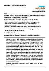
Figure 2 reveals the solute element distribution of MZM-xCa with 380 °C/24 h treatment. It can be seen that the distribution of Mn element was uniform along the matrix while Zn/Ca were gathered Materials 2018, 11, x FOR PEER REVIEW 5 of 17 in localized the volume fraction of phases with (Mg2380 Ca ◦+C/24 Ca2Mg 6Zn3) increased Figure 2 areas. revealsIntheaddition, solute element distribution of MZM-xCa h treatment. It can gradually as the Ca content increased, ranging from 0.26% to 1.93%, which was consistent with be seen that the distribution of Mn element was uniform along the matrix while Zn/Ca were gathered Figure 2 reveals the solute element distribution of MZM-xCa with 380 °C/24 h treatment. It can SEM morphologies. Figure showsofthe XRD patterns of studied alloys and as-cast state. It in localized areas. In3 addition, the volume of phases (Mgcompared Ca +Zn/Ca Ca2with Mg be seen that the distribution Mn element wasfraction uniform along the matrix were gathered 2while 6 Zn 3 ) increased in localized Inthe addition, the volume fraction of phases 2which Ca mainly + Ca 2Mg 6Zn3) increased can be concluded as-cast MZM-xCa alloys (Figure 3a)(Mg were composed of α-Mg, gradually as the areas. Cathat content increased, ranging from 0.26% to 1.93%, was consistent with SEM gradually the Ca2content to 1.93%, which was consistent with SEM Mg 2Ca, MgZn,asFigure MgZn Caincreased, 2Mg 3,ranging and thefrom homogenization MZM-xCa alloyswith (Figure 3b) were morphologies. 3and shows the6Zn XRD patterns of0.26% studied alloys and compared as-cast state. morphologies. Figure shows the patterns ofreason studied alloys and compared withcomposed as-cast state. Itα-Mg, composed of α-Mg, Mg and Ca2XRD Mg 6Zn3. Thealloys for the3a) component discrepancy wasofmainly It can be concluded that23Ca the as-cast MZM-xCa (Figure were mainly can be concluded that the as-cast MZM-xCa alloys (Figure 3a) were mainly composed of α-Mg, attributed to Zn/Ca dissolving homogenization treatment (Figure 3c). Mg2 Ca, MgZn, MgZn Mg6Mg Zn3substrate , and the after homogenization MZM-xCa alloys (Figure 3b) were 2 and Ca2into Mg2Ca, MgZn, MgZn2 and Ca2Mg6Zn3, and the homogenization MZM-xCa alloys (Figure 3b) were composed of α-Mg, Mg2 Ca and Ca2 Mg6 Zn3 . The reason for the component discrepancy was mainly composed of α-Mg, Mg2Ca and Ca2Mg6Zn3. The reason for the component discrepancy was mainly attributed to Zn/Ca dissolving afterhomogenization homogenization treatment (Figure attributed to Zn/Ca dissolvinginto intoMg Mg substrate substrate after treatment (Figure 3c). 3c).
Figure 2.The The elements distribution samples with treatment: (a) MZM; (b) MZMFigure 2.2.The elements distribution ofofsamples withhomogenization homogenization treatment: (a) MZM; (b) MZMelements distribution of samples with homogenization treatment: (a) MZM; 0.38% Ca; (c) MZM-0.76% Ca; and (d) MZM-1.10% Ca. 0.38% Ca; (c) MZM-0.76% Ca; and (d) MZM-1.10% Ca. (b) MZM-0.38% Ca; (c) MZM-0.76% Ca; and (d) MZM-1.10% Ca.
Figure 3. Cont.
Materials 2018, 11, 227
6 of 17
Materials 2018, 11, x FOR PEER REVIEW
6 of 17
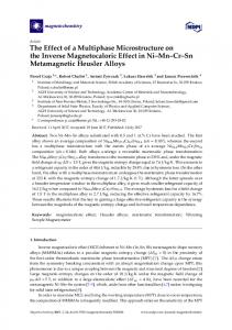
Figure 3. X-ray diffractions patterns of: (a) as-cast MZM-xCa alloys; and (b) homogenization state;
Figure 3. X-ray diffractions patterns of: (a) as-cast MZM-xCa alloys; and (b) homogenization state; and (c) JmatPro calculations results for the microstructure transformation of MZM-1.10% Ca alloy and (c)depending JmatPro calculations results for the microstructure transformation of MZM-1.10% Ca alloy on temperature. depending on temperature. To ascertain the phase structure, TEM observation was further conducted. Figure 4 shows the TEM morphology of MZM-1.10% Ca alloys, and the random distribution of precipitation phases were To ascertain the phase structure, TEM observation was further conducted. Figure 4 shows the detected. In addition, Figure 4a–c presents the different morphologies of precipitation phases, such TEM morphology of MZM-1.10% Ca alloys, and the random distribution of precipitation phases as short-rod shape and granular shape. Figure 4d presents the HRTEM images and selected area were detected. addition, Figure presents(Figure the different morphologies of precipitation diffractionInpattern (SADP) of the4a–c precipitation 4c), in which the interplanar space was 0.84 phases, such asnm. short-rod shape and Figure 4d presents andofselected It was consistent withgranular the value shape. of Ca2Mg 6Zn3 (100). Moreover,the the HRTEM elemental images distribution precipitatespattern is presented in Figure 4e,precipitation which further verified validity of TEM results. In a similar area diffraction (SADP) of the (Figurethe4c), in which the interplanar space was way, the precipitation of Mg 2Ca was also identified, and the details are shown in Figure 4f–h. 0.84 nm. It was consistent with the value of Ca Mg Zn (100). Moreover, the elemental distribution of 2
6
3
precipitates is presented in Figure 4e, which further verified the validity of TEM results. In a similar way, the precipitation of Mg2 Ca was also identified, and the details are shown in Figure 4f–h.
Figure 4. Cont.
Materials 2018, 11, 227
7 of 17
Figure 4. (a,b) Typical TEM phase features of as-studied MZM-1.10% Ca alloys; (c) TEM phase; (d) high resolution morphology; and (e) element distributions of Ca2 Mg6 Zn3 marked in (c); (f) TEM phase; (g) selected area diffraction patters; and (h) EDS analysis of Mg2 Ca phase marked in (f).
3.2. Electrochemical Measurements Figure 5 shows the electrochemical behaviors of homogenization MZM-x Ca alloys as a function of Ca content in the Kokubo solution at 37 ◦ C, and the fitted results are summarized in Table 3. As indicated, as the Ca content increased, the MZM-0.38% Ca alloys shifted to a more positive potential (−1.57 VSCE ) compared to the MZM alloy. However, the sample of MZM-(0.76% Ca, 1.10% Ca) unexpectedly shifted to a negative potential (Figure 5a), in which the values were −1.63 V and −1.68 V, respectively. Based on the electrochemical theory, the Ecorr of samples depends mainly on the relative magnitude between the anodic and cathode reaction rates, which reflected the reaction tendency [27]. Besides, the corrosion current density (Icorr ) was presented in a decreasing order: MZM-1.10 Ca < MZM-0.76 Ca < MZM < MZM-0.38 Ca. Lower current density means better corrosion resistance. Thus, it indicated that the MZM-0.38% Ca sample with 380 ◦ C/24 h treatment possesses the noblest corrosion potential, smallest current density and best corrosion resistance. It was associated with the combined effects of the suitable content of Zn/Ca dissolving into the α-Mg matrix and the modification of Ca-containing compounds by heat-treatment. Thus, the corrosion resistance was improved. However, the excess Ca content present in the matrix could generate intermetallic and form micro-galvanic effect, which accelerated the Mg substrates dissolution. Figure 5b–d reveals the EIS spectra of MZM-xCa alloys in Kokubo solution. In the case of Nyquist plots (Figure 5b), the curve dimensions have different values, which are ranked in an increasing order as follows: MZM-1.10 Ca < MZM-0.76 Ca < MZM < MZM-0.38 Ca, corresponding to an increasing impedance trend of the MZM-xCa alloys in the curves (Bode plots of |Z| vs. frequency) in Figure 5c. As known, the dimension size of the Nyquist plots was the important parameters to reflect the corrosion resistance. Namely, better corrosion behavior of the metal matrix is associated with the higher Z modulus at lower frequency, which is reciprocal to the correlation of corrosion rate for the alloys. In the case of bode phase plot (phase angle vs. frequency), it can be seen that the phase angles
Materials 2018, 11, 227
8 of 17
Materials 2018, 11, x FOR PEER REVIEW
8 of 17
of the high frequency capacity resistance crests decrease in the sequence MZM-0.38 Ca > MZM > >MZM-0.76 MZM-0.76Ca Ca>>MZM-1.10 MZM-1.10Ca, Ca,which whichcan canbe beattributed attributedto tothe the protective protective performance performance of the surface film layers. As a result, the test results were consistent with polarization polarization curves. curves.
Figure 5. Electrochemical Electrochemical behaviors behaviors of MZM-xCa alloys in a simulated body fluid: (a) polarization (b) nyquist nyquist plots; plots; (c) (c)bode bodeplots plotsofof|Z| |Z|vs.vs. frequency; bode plots of phase angle curves; (b) frequency; andand (d)(d) bode plots of phase angle vs. vs. frequency. frequency. Table 3. Result of the electrochemical polarization tests in SBF solution. solution.
Alloys Ecorr (VSCE ) ) Alloys Ecorr (VSCE MZM −1.63 MZM −1.63 MZM-0.38 Ca −1.576 MZM-0.38 Ca −1.576 MZM-0.76 Ca Ca −1.67 MZM-0.76 −1.67 MZM-1.1 Ca −1.752 MZM-1.1 Ca −1.752
Icorr(µA/cm (μA/cm 2 ) 2) Icorr
Pi (mm/y) Pi (mm/y)
289.93 274.41 274.41 356.20 356.20 400.31 400.31
6.62 6.27 6.27 8.14 8.14 9.15 9.15
289.93
6.62
3.3. Immersion Test Figure 6 presents the SEM micrographs of corrosion morphology of MZM-xCa in the Kokubo ◦ C for 10 days. As can be seen, the substantial corrosion products were covered on solution at at 37 37 °C for 10 days. As can be seen, the substantial corrosion products were covered on the the surface cracks features, wastodue to the dehydration when they removed the surface withwith cracks features, whichwhich was due the dehydration when they removed from thefrom Kokubo Kokubo solution. In addition, flat and surface smooth was surface was obtained in of sample MZM, MZM-0.38 solution. In addition, a flat anda smooth obtained in sample MZM,ofMZM-0.38 Ca and Ca and MZM-0.76 Ca. In contrast, severe corrosion morphology withsize large size of pitting holes and MZM-0.76 Ca. In contrast, a severeacorrosion morphology with large of pitting holes and multimulti-defects features was observed in MZM-1.10 Ca. The composition of the products is summarized defects features was observed in MZM-1.10 Ca. The composition of the products is summarized in in the Figure 6 inset. It can be seen that the corrosion products were primarily composed of Mg, O, the Figure 6 inset. It can be seen that the corrosion products were primarily composed of Mg, O, P, C P, C Ca andelements. Ca elements. Furthermore, the elements distribution of products was shown in Figure 7. and Furthermore, the elements distribution of products was shown in Figure 7. These These elements such O and Ca corresponded to each other, which indicatedthe thepresence presenceof of (Mg, (Mg, elements such as P, as O P, and Ca corresponded to each other, which indicated Ca)33(PO (PO44))22(insoluble) (insoluble)in inthe theproducts. products.To Tofurther further study study the the composition composition of of corrosion products, XRD and XPS were employed to determine the results, as shown in Figure 8. 8. XRD results indicated the corrosion products were primary composed of Mg, Mg(OH)2 and a small quantity of hydroxyapatite (HA). As shown in Figure 8b, the XPS test identified the corrosion products consist of O−, OH−, CO32−,
Materials 2018, 11, 227
9 of 17
corrosion products Materials 2018, 11, x FORwere PEER primary REVIEW
composed of Mg, Mg(OH)2 and a small quantity of hydroxyapatite 9 of 17 (HA). As shown in Figure 8b, the XPS test identified the corrosion products consist of O− , OH− , 2+ and 2− Ca2+ 2+ 2+ .results PO . Thus, the XPSofand XRD consistent which was CO332−2,−Mg , PO and Ca Thus, of theEDS, results EDS, XPShave andaXRD have aconclusion, consistent conclusion, 3 , Mg also in was goodalso agreement previous [6,24,38,45]. which in good with agreement withstudies previous studies [6,24,38,45].
Figure immersion test: (a)(a) MZM; (b)(b) MZM-0.38% Ca; Ca; (c) Figure 6. 6. SEM SEMmicrographs micrographsofofcorrode corrodesurface surfaceafter after immersion test: MZM; MZM-0.38% MZM-0.76% Ca; and (d) MZM-1.10% Ca. (c) MZM-0.76% Ca; and (d) MZM-1.10% Ca.
Figure 7.7.Elements distribution of corrosion products for MZM-1.10% Ca alloys: (a) morphologies; Figure Elements distribution of corrosion products for MZM-1.10% CaSEM alloys: (a) SEM and (b) main solute elements distribution. morphologies; and (b) main solute elements distribution.
Materials 2018, 11, 227 Materials 2018, 2018, 11, 11, xx FOR FOR PEER PEER REVIEW REVIEW Materials
10 of 17 10 of of 17 17 10
XRD and and XPS XPS spectrum spectrum of corrosion corrosion products products of of MZM-xCa MZM-xCa alloys: alloys: (a) (a) XRD; XRD; and and (b) (b) XPS. XPS. Figure 8. XRD products of MZM-xCa alloys:
Besides, the the3D 3D corrosion morphologies of as-received MZM-xCa alloystheafter the products Besides, corrosion morphologies of as-received MZM-xCa alloys after products removal removal are shown in Figure 9, which were characterized by laser scanning confocal microscopy are shown in Figure 9, which were characterized by laser scanning confocal microscopy (CLSM). (CLSM). As indicated, the experiment alloys surface exhibit colors the different colors profiles, and corrosion As indicated, the experiment alloys surface exhibit the different and corrosion which profiles, which reflected and represented the different corrosion performance of as-received alloys in reflected and represented the different corrosion performance of as-received alloys in a simulated body a simulated fluid [45–47].the Assurface for thewas MZM, the corroded surface was corroded and exhibited fluid [45–47].body As for the MZM, slightly andslightly exhibited some shallow pitting some shallow pitting holes. The MZM-0.38 Ca alloy revealed a smooth surface, and the fluctuation holes. The MZM-0.38 Ca alloy revealed a smooth surface, and the fluctuation of profile curves was of profile curves was also relatively slight. With increasing Ca content, the volume fraction of the also relatively slight. With increasing Ca content, the volume fraction of the compounds remarkably compoundswhich remarkably increased, which can arise from micro-galvanic corrosion. large size to of increased, can arise from micro-galvanic corrosion. The large size of pittingThe holes began pitting holes began to generate and propagate, as shown in Figure 9c,d. Furthermore, the data in generate and propagate, as shown in Figure 9c,d. Furthermore, the data in Table 4 relate to the Table 4 relate corrosion ii. Themethods results from both methods show thatwt addition of 0.38 % corrosion rateto Pithe . The results rate fromPboth show that addition of 0.38 % Ca has thewt best Ca has the best corrosion resistance. As for the pH measurements (Figure 10), the MZM-0.38 Ca still corrosion resistance. As for the pH measurements (Figure 10), the MZM-0.38 Ca still possesses the possesses lowindicating value of pH, indicating the lowest corrosion which with was electrochemical consistent with low value the of pH, the lowest corrosion rate, which wasrate, consistent electrochemicaland measurements and immersion test. measurements immersion test.
Figure 9. Cont.
Materials 2018, 11, 227 Materials 2018, 11, x FOR PEER REVIEW
11 of 17 11 of 17
Materials 2018, 11, x FOR PEER REVIEW
11 of 17
Figure 9. 3D corrosion morphology MZM-xCa alloys alloys with homogenization treatment: (a) 0%; Figure ofof MZM-xCa with homogenization treatment: (a) (b) 0%; (b) Figure 9. 9. 3D 3Dcorrosion corrosionmorphology morphology of MZM-xCa alloys with homogenization treatment: (a) 0%; 0.38%; (c) 0.76%; and (d) 1.10%. 0.38%; (c) 0.76%; andand (d) 1.10%. (b) 0.38%; (c) 0.76%; (d) 1.10%. Table 4. Measurements related to corrosion rate in simulated body fluid at 37 °C.
◦ C. Table Table 4. 4. Measurements Measurements related related to to corrosion corrosion rate rate in in simulated simulated body body fluid fluid at at 37 37 °C. Icorr ΔWm Pi Pm Ecorr (V) Alloys I(μA/cm ΔW corr m Pi Pm 2)2 2/d) (mm/y) (mg/cm (mm/y) 2 Alloys Pi (mm/y) (V) Pm (mm/y) EEcorr Alloys Icorr (µA/cm ) ∆Wm (mg/cm /d) corr(V) 2) 2/d) (μA/cm (mm/y) (mg/cm (mm/y) MZM 289.9 6.61 −1.63 6.95 14.59 MZM 289.9 6.61 −1.63 6.95 14.59 MZM 289.9 6.61 −1.63 6.95 14.59 MZM-0.38 Ca 274.4 6.27 −1.58 5.62 11.80 MZM-0.38 Ca 274.4 6.27 −1.58 5.62 11.80 MZM-0.76 356.2 8.14 −1.67 8.87 18.63 MZM-0.76 356.2 8.14 −1.67 8.87 18.63 MZM-0.38 CaCaCa 274.4 6.27 −1.58 5.62 11.80 MZM-1.1 400.3 9.14 −1.75 11.18 23.47 MZM-1.1 400.3 9.14 −1.75 11.18 23.47 MZM-0.76 CaCaCa 356.2 8.14 −1.67 8.87 18.63
MZM-1.1 Ca
400.3
9.14
−1.75
11.18
23.47
Figure 10. pH value the studiedalloys alloys during during the test in Kokubo solution. Figure 10. pH value of of the studied theimmersion immersion test in Kokubo solution.
3.4. Biocompatibility Assessment
3.4. Biocompatibility Assessment
Figure 10. pHofvalue of the studiedinalloys the immersion testone, in Kokubo solution. Cell viability BMSCs cultured 100%during extraction medium for two and three days is
Cell viability of BMSCs cultured in that, 100%after extraction for one, three days is shown shown in Figure 11. It could be seen one daymedium of cultivation, thetwo cellsand in extracts showed 3.4. Biocompatibility Assessment in Figure 11. It could be seen that, after one day of cultivation, the cells in extracts showed slightly slightly lower viability than that of the control group (Figure 11a). After two and three days in culture ofviability materials’than extracts, the from MZM group exhibited lowertwo viability,three but not a significant lower of cells the control 11a).still After days in culture Cell viability of that BMSCs cultured ingroup 100%(Figure extraction medium for and one, two and three days of is one, than the negative control group, and the exhibited cytotoxicitystill of these extracts wasbut Grade 0–1 according one, materials’ extracts, the cells from MZM group lower viability, not a significant shown in Figure 11. It could be seen that, after one day of cultivation, the cells in extracts showed to ISO 10993-5:1999, thatthe the cytotoxicity MZM alloys did not induce toxicity to BMSCs. than the negative controlindicating group, and of these extracts was Grade 0–1Nevertheless, according to ISO slightly lower viability that thein control 11a). After two andviability three days in culture as shown in Figure than 11b–d, theofcells others group extracts(Figure exhibited a relatively high compared 10993-5:1999, indicating that the MZM alloys did not induce toxicity to BMSCs. Nevertheless, as shown of materials’ extracts, the cells from MZM group exhibited still lower viability, but not a significant in Figure the cells in others extracts exhibited a relatively high viability compared to the former. one, than 11b–d, the negative control group, and the cytotoxicity of these extracts was Grade 0–1 according It indicated that the extracts canthat offerthe a suitable environment for BMSCs proliferation. Among the four to ISO 10993-5:1999, indicating MZM alloys did not induce toxicity to BMSCs. Nevertheless,
as shown in Figure 11b–d, the cells in others extracts exhibited a relatively high viability compared
Materials 2018, 11, x FOR PEER REVIEW Materials 2018, 11,11, 227 Materials 2018, x FOR PEER REVIEW
12 of 17 of 17 12 12 of 17
to the former. It indicated that the extracts can offer a suitable environment for BMSCs proliferation. to the former. indicated that the extracts can offer aexhibits suitable environment BMSCs proliferation. Among the fourItspecimens, the MZM-0.38% Ca alloy the highest cell for viability, reaching 108% specimens, thefour MZM-0.38% Ca alloy exhibitsCa thealloy highest cell the viability, reaching 108%reaching after three-day Among the specimens, the MZM-0.38% exhibits highest cell viability, 108% after three-day cultivation. The better cell proliferation could be attributed to the synergetic effects of cultivation. The better cell proliferation could be attributed to the synergetic effects of the release after three-day cultivation. The better cell proliferation could be attributed to the synergetic effects of 2+ 2+ 2+ the release of suitable Mg , Ca , and Zn accompanied by a moderate degradation rate of the MZM2+ , Ca2+ , and 2+ 2+, Zn 2+, and 2+ accompanied of0.38% suitable Mg accompanied by a moderate degradation rate of the MZM-0.38% the release of suitable Mg Ca Zn by a moderate degradation rate of the MZMCa specimen. In addition, the cells grown in different extracts exhibited a healthy, spindle0.38% Ca specimen. In addition, the cells grown in different extracts exhibited healthy, Cashaped specimen. In addition, the cells grown in different extracts exhibited a healthy, spindle-shaped morphology, which was similar to that of the negative control group. As aaresult, thespindleresults shaped morphology, which was similar to that of the negative control group. As a result, the results morphology, which was similar to that of the negative control group. As a result, the results of cell of cell viability and cell morphology observation (Figures 11 and 12) showed that as-homogenized of cell viability and cell morphology observation (Figures 11 and 12) showed that as-homogenized viability and alloys cell morphology observation andmet 12) the showed that as-homogenized MZM-xCa MZM-xCa did not induce toxicity(Figures to cells11 and biocompatibility requirements for MZM-xCa alloys did not induce toxicity to cells and met the biocompatibility requirements for alloys did not induce toxicity to cells and met the biocompatibility requirements for implant materials. implant materials. implant materials.
Figure11.11.The TheBMSCs BMSCsviability viabilityininnegative negativecontrol controland andMZM-xCa MZM-xCaalloys alloysextractions extractionsafter afterone, one,two twoand Figure Figure 11.days TheofBMSCs viability in negative control Ca; and(c) MZM-xCa alloys after one, Ca. two and three culture. (a) MZM; (b) MZM-0.38% MZM-0.76% Ca;extractions and (d) MZM-1.10% three days of culture. (a) MZM; (b) MZM-0.38% Ca; (c) MZM-0.76% Ca; and (d) MZM-1.10% Ca. and three days of culture. (a) MZM; (b) MZM-0.38% Ca; (c) MZM-0.76% Ca; and (d) MZM-1.10% Ca.
Figure 12. Optical microscopy of BMSCs after three days of incubation: (a) negative control; (b) MZM Figure 12. Optical microscopy of BMSCs after three days of incubation: (a) negative (b) MZM extracts; MZM-0.38 Ca extracts; (d) MZM-0.76 Cadays extracts; and (e) MZM-1.10 Cacontrol; extracts. Figure 12. (c) Optical microscopy of BMSCs after three of incubation: (a) negative control; All (b) the MZM extracts; (c) MZM-0.38 Ca extracts; (d) MZM-0.76 Ca extracts; and (e) MZM-1.10 Ca extracts. All the scale bar represents 20 μm. extracts; (c) MZM-0.38 Ca extracts; (d) MZM-0.76 Ca extracts; and (e) MZM-1.10 Ca extracts. All the scale bar represents 20 μm. scale bar represents 20 µm.
Materials 2018, 11, 227 Materials 2018, 11, x FOR PEER REVIEW
13 of 17 13 of 17
alloys in the the Kokubo Kokubo solution, solution, Aimed to further analyze the corrosion mechanism of MZM-xCa alloys the SKPFM were used to detect the surface Volta potential distributions. The second phase particles Volta potential distributions. brightercolor color(white (white color) than surrounding matrix, indicating the difference in exhibited aabrighter color) than thethe surrounding matrix, indicating the difference in Volta Volta potentials, as shown in Figure 13. the In the MZM, MZM-0.38 Ca,almost almostno noor or trace trace of potentials, as shown in Figure 13. In casecase of of MZM, MZM-0.38 Ca, precipitatons were detected and exhibited a uniform distribution distribution of of Volta potential with relative corresponding to a better corrosion resistance [45,47]. As As for the Figure 13d, the large noble value, corresponding size of compounds/phases could be observed, which caused the huge difference in in Volta potentials compounds/phases could be observed, which caused the huge difference between the matrix and phases. Moreover, with the Ca content increased, the large size and volume 1, Figure 2, and which fractions of of phases phases(Mg (Mg2 Ca 2Caand andCa Ca 2Mg 6Zn wereobserved observed(Figure (Figures 1, 2, and 13),Figure which13), gathered 2 Mg 6 Zn 33))were gathered along the grain boundaries, and exhibited a dots-chains distribution. Furthermore, the along the grain boundaries, and exhibited a dots-chains distribution. Furthermore, the morphologies morphologies werefrom transformed uniform localized pittingwith corrosion with Ca further were transformed uniformfrom corrosion to corrosion localized to pitting corrosion Ca further addition addition 6(Figures 6 and 9).beItexplained could be explained that theCa excessive Cacan addition can strengthen the (Figures and 9). It could that the excessive addition strengthen the nucleation nucleation driving force for the formation of precipitations (Mg Ca and Ca Mg Zn ), and the large driving force for the formation of precipitations (Mg2Ca and Ca 2 2Mg6Zn3),2 and6 the3 large volumes volumes of micro-galvanic present sites interface sites accelerate the nucleation driving force for fraction offraction micro-galvanic present interface accelerate the nucleation driving force for corrosion corrosion propagation. propagation.
Figure 13. Surface SurfaceVolta Voltapotential potential distribution of MZM-xCa. (a) (b) 0%;0.38%; (b) 0.38%; (c) 0.76%; (d) Figure 13. distribution of MZM-xCa. (a) 0%; (c) 0.76%; and (d)and 1.10%. 1.10%.
Moreover, the preferential corrosion areas were also observed at the interface positions, as shown Moreover, the preferential corrosion areas were also observed at the interface positions, as in Figure 14. The schematic of corrosion mechanism is shown in Figure 15. When the fresh surface shown in Figure 14. The schematic of corrosion mechanism is shown in Figure 15. When the2+fresh exposed to electrode containing corrosive ions, the Mg would immediately transfer into Mg and surface exposed to −electrode containing corrosive ions, the Mg would immediately transfer into Mg2+ combine with OH to deposit Mg(OH)2 accompanied by the evolution of hydrogen (Figure 15a, and combine with OH− to deposit Mg(OH) 2 accompanied by the evolution of hydrogen (Figure 15a, Equation (4)). Prolonged the immersion time, the film layer formation and rupture were under a Equation (4)). Prolonged the immersion time, the film layer formation−and rupture were under a dynamic balance (Figure 15b, Equations (3) and (4)). Besides, the more OH ions present in the Kokubo dynamic balance (Figure 15b, Equations (3)3−and (4)). Besides, more OH− ions present the 2− to PO 3−the 2+ andin solution convert H2 PO4 − and HO , and these PO ions can react with Ca Mg2+ 4 4 4 − 2− 3− 3− 2+ Kokubo solution convert H2PO4 and HO4 to PO4 , and these PO4 ions can react with Ca and Mg2+ in the electrolyte (Equations (6) and (7)) and result in the formation of calcium phosphate base apatite in the electrolyte (Equations (6) and (7)) and result in the formation of calcium phosphate base apatite precipitations according to Equation (8). However, with further extension of the immersion time, the precipitations according to Equation (8). However, with further extension of the immersion time, the presence of abundant Cl− in Kokubo solution exerts the film layer more active and vulnerable to presence of abundant Cl− in Kokubo solution exerts the film layer more active and vulnerable to rupture (Figure 15c, Equation (4)). Besides, the defects, such as micro-cracks and vacancies, can provide rupture (Figure 15c, Equation (4)). Besides, the defects, such as micro-cracks and vacancies, can diffusion channels for Cl− into film −structure to react with MgO and Mg(OH)2 , which accelerated the provide diffusion channels for Cl into film structure to react with MgO and Mg(OH)2, which dissolution rate of the Mg substrate and caused the formation of localized corrosion (Figure 15d). accelerated the dissolution rate of the Mg substrate and caused the formation of localized corrosion (Figure 15d).
Materials 2018, 11, x FOR PEER REVIEW Materials 2018, 11, 227
14 of 17 14 of 17
Figure 14. Preferential corrosion areas and morphologies were detected by SEM.
1
Figure 14. Preferential corrosion areas and morphologies were detected by SEM.
n Mg
1
n H O
1
n OH → 1
n Mg OH
1/2 1
n H
(3)
(1 − n) Mg+ + (1 − n) H2 O + (1 − n) OH− → (1 − n) Mg(OH)2 + 1/2 (1 + n) H2 Mg OH 2Cl → MgCl 2OH
(3) (4)
Mg(OH)2 + 2Cl− → MgCl2 + 2OH− H PO OH → H PO H O − − 2− H2 PO4 + OH → H2 PO4 + H2 O H PO 2OH− → PO 3− 2H O H2 PO4 + 2OH → PO4 − + 2H2 O
(4) (5) (5) (6) (6)
2+ 3Ca 2PO3− + mH mH2 OO → → Ca mH 2O 3Ca + 2PO Ca3 (PO PO4 )2 ·mH O(TCP TCP) 4
(7) (7)
2+ 2− − 10Ca + 8OH 6H2OO(HA HA) 4 PO4 )6 (OH 10Ca + 6HPO 6HPO 8OH →→ Ca Ca10 (PO OH )2 + 6H
(8) (8)
corrosion mechanism mechanism of of as-studied as-studied alloys alloys in in the theKokubo Kokubosolution. solution. Figure 15. Schematic illustration of corrosion
Materials 2018, 11, 227
15 of 17
4. Conclusions (1) (2)
(3)
(4)
Electrochemical tests and immersion results both showed that MZM-0.38 Ca has the best corrosion resistance, and yields a uniform corrosion morphology on the surface. The improvement of corrosion resistance could be attributed to the combined effects of the suitable content of Zn/Ca dissolving in α-Mg matrix and the modification of Ca-containing compounds by homogenization treatment. With the increase of Ca content, nucleation driving forces for the phases formation were facilitated and the microstructure was refined. However, the large volume fraction of micro-galvanic presence between α-Mg and phase accelerates the micro-galvanic corrosion. In vitro biocompatibility tests show the MZM-xCa alloys were safe to human bone marrow mesenchymal stem cells and were promising to be utilized as implant materials in the future.
Acknowledgments: This research is supported by the financial support of the National Key Research and Development Program of China 2016YFB0700300 and 2016YFB0300901. Author Contributions: Jingyuan Li and Yuan Zhang conceived and designed the experiments; Yuan Zhang and Huiying Lai performed the experiments; Yuan Zhang and Yuzhao Xu analyzed the data; Jingyuan Li, Yuan Zhang contributed reagents/materials/analysis tools; and Yuan Zhang wrote the paper. Conflicts of Interest: The authors declare no conflict of interest.
References 1.
2.
3. 4.
5. 6.
7. 8. 9. 10. 11. 12. 13. 14.
Singh, S.; Kumar, R.M.; Kuntal, K.K.; Gupta, P.; Das, S.; Jayaganthan, R.; Roy, P.; Lahiri, D. Sol-gel derived hydroxyapatite coating on Mg-3Zn alloy for orthopedic application. J. Miner. Met. Mater. Soc. 2015, 67, 702–712. [CrossRef] Shi, Y.J.; Zhang, L.; Chen, J.H.; Zhang, J.; Yuan, F.; Shen, L.; Chen, C.X.; Pei, J.; Li, Z.H.; Tan, J.Y.; et al. In vitro and in vivo degradation of rapamycin-eluting Mg-Nd-Zn-Zr alloy stents in porcine coronary arteries. Mater. Sci. Eng. C 2017, 80, 1–6. [CrossRef] [PubMed] Witte, F.; Feyerabend, F.; Maier, P.; Fischer, J.; Störmer, M.; Blawert, C.; Dietzel, W.; Hort, N. Biodegradable magnesium-hydroxyapatite metal matrix composites. Biomaterials 2007, 28, 2163–2174. [CrossRef] [PubMed] Jaiswal, S.; Manoj Kumar, R.; Gupta, P.; Kumaraswamy, M.; Roy, P.; Lahiri, D. Mechanical, corrosion and biocompatibility behaviour of Mg-3Zn-HA biodegradable composites for orthopaedic fixture accessories. J. Mech. Behav. Biomed. 2018, 78, 442–454. [CrossRef] [PubMed] Zeng, R.C.; Li, X.T.; Liu, L.J.; Li, S.Q.; Zhang, F. In vitro Degradation of Pure Mg for Esophageal Stent in Artificial Saliva. J. Mater. Sci. Technol. 2016, 32, 437–444. [CrossRef] Wong, P.C.; Tsai, P.H.; Li, T.H.; Cheng, C.K.; Jang, J.S.C.; Huang, J.C. Degradation behavior and mechanical strength of Mg-Zn-Ca bulk metallic glass composites with Ti particles as biodegradable materials. J. Alloys Compd. 2017, 699, 914–920. [CrossRef] Song, G.L. Control of biodegradation of biocompatible magnesium alloys. Corros. Sci. 2007, 49, 1696–1701. [CrossRef] Shubhakar-Nidadavolu, E.P.; Feyerabend, F.; Ebel, T.; Willumeit-Römer, R.; Dahms, M. On the determination of magnesium degradation rates under physiological conditions. Materials 2016, 9, 627. [CrossRef] [PubMed] Chiu, C.; Lu, C.T.; Chen, S.H.; Ou, K.L. Effect of hydroxyapatite on the mechanical properties and corrosion behavior of Mg-Zn-Y alloy. Materials 2017, 10, 855. [CrossRef] [PubMed] Singh Raman, R.K.; Harandi, S.E. Resistance of Magnesium Alloys to Corrosion Fatigue for Biodegradable Implant Applications: Current Status and Challenges. Materials 2017, 10, 1316. [CrossRef] [PubMed] Wang, L.Q.; Qin, G.W.; Sun, S.N.; Ren, Y.P.; Li, S. Effect of solid solution treatment on in vitro degradation rate of as-extruded Mg-Zn-Ag alloys. Trans. Nonferr. Metal. Soc. 2017, 27, 2607–2617. [CrossRef] Padekar, B.S.; Singh Raman, R.K.; Raja, V.S.; Paul, L. Stress corrosion cracking of a recent rare-earth containing magnesium alloy, EV31A, and a common Al-containing alloy, AZ91E. Corros. Sci. 2013, 71, 1–9. [CrossRef] Zheng, Y.F.; Gu, X.N.; Witte, F. Biodegradable metals. Mater. Sci. Eng. R 2014, 77, 1–34. [CrossRef] Ahmed, S.K.; Ward, J.P.; Liu, Y. Numerical Modelling of Effects of Biphasic Layers of Corrosion Products to the Degradation of Magnesium Metal In Vitro. Materials 2018, 11, 1. [CrossRef] [PubMed]
Materials 2018, 11, 227
15. 16.
17. 18. 19.
20.
21. 22.
23. 24.
25.
26. 27. 28. 29.
30. 31.
32. 33. 34.
35.
16 of 17
Song, G.L.; Song, S. A possible biodegradable magnesium implant material. Adv. Eng. Mater. 2007, 9, 298–302. [CrossRef] Liu, L.; Yuan, F.L.; Zhao, M.C.; Gao, C.D.; Feng, P.; Yang, Y.W.; Yang, S.; Shuai, C.J. Rare Earth Element Yttrium Modified Mg-Al-Zn Alloy: Microstructure, Degradation Properties and Hardness. Materials 2017, 10, 477. [CrossRef] [PubMed] Gu, X.N.; Xie, X.H.; Li, N.; Zheng, Y.F.; Qin, L. In vitro and in vivo studies on a Mg-Sr binary alloy system developed as a new kind of biodegradable metal. Acta Biomater. 2012, 6, 2360–2374. [CrossRef] [PubMed] Chen, Y.A.; Gao, J.J.; Song, Y.; Wang, Y. The influences of Sr on the microstructure and mechanical properties of Mg-5Zn-2Al alloy. Mater. Sci. Eng. A 2016, 671, 127–134. [CrossRef] Liu, X.W.; Sun, J.K.; Yang, Y.H.; Zhou, F.Y.; Pu, Z.J.; Li, L.; Zheng, Y.F. Microstructure, mechanical properties, in vitro degradation behavior and hemocompatibility of novel Zn-Mg-Sr alloys as biodegradable metals. Mater. Lett. 2016, 162, 242–245. [CrossRef] Vlˇcek, M.; Lukáˇc, F.; Kudrnová, H.; Smola, B.; Stulíková, I.; Luczak, M.; Gábor Szakács, G.; Norbert Hort, N.; Willumeit-Römer, R. Microhardness and In Vitro Corrosion of Heat-Treated Mg-Y-Ag Biodegradable Alloy. Materials 2017, 10, 55. [CrossRef] [PubMed] Wang, S.D.; Xu, D.K.; Chen, X.B.; Han, E.H.; Dong, C. Effect of heat treatment on the corrosion resistance and mechanical properties of an as-forged Mg-Zn-Y-Zr alloy. Corros. Sci. 2015, 92, 228–236. [CrossRef] Qin, H.; Zhao, Y.C.; An, Z.Q.; Cheng, M.Q.; Wang, Q.; Cheng, T.; Wang, Q.J.; Wang, J.X.; Jiang, Y.; Zhang, X.L.; et al. Enhanced antibacterial properties, biocompatibility, and corrosion resistance of degradable Mg-Nd-Zn-Zr alloy. Biomaterials 2015, 53, 211–220. [CrossRef] [PubMed] Bian, D.; Zhou, W.R.; Liu, Y.; Li, N.; Zheng, Y.F.; Sun, Z.L. Fatigue behaviors of HP-Mg, Mg-Ca and Mg-Zn-Ca biodegradable metals in air and simulated body fluid. Acta Biomater. 2016, 41, 351–360. [CrossRef] [PubMed] Dolezal, P.; Zapletal, J.; Fintova, S.; Trojanova, Z.; Greger, M.; Roupcova, P.; Podrabsky, T. Influence of processing techniques on microstructure and mechanical properties of a biodegradable Mg-3Zn-2Ca alloy. Materials 2016, 9, 11. [CrossRef] [PubMed] Terent’ev, V.F.; Dobatkin, S.V.; Prosvirnin, D.V.; Bannykh, I.O.; Kopylov, V.I.; Serebryany, V.N. Fatigue strength of a magnesium MA2-1 alloy after equal-channel angular pressing. Russ. Metall. 2011, 2010, 824–830. [CrossRef] Chen, Y.; Xu, Z.; Smith, C.; Sankar, J. Recent advances on the development of magnesium alloys for biodegradable implants. Acta Biomater. 2014, 10, 4561–4573. [CrossRef] [PubMed] Anawati, A.; Asoh, H.; Ono, S. Effects of alloying element Ca on the corrosion behavior and bioactivity of anodic films formed on AM60 Mg alloys. Materials 2017, 10, 11. [CrossRef] [PubMed] Zhao, J.; Gao, L.L.; Yuan, X.; Chen, X. Biodegradable behaviour and fatigue life of ZEK100 magnesium alloy in simulated physiological environment. Fatigue Fract. Eng. Mater. Struct. 2015, 38, 904–913. [CrossRef] Cheng, W.L.; Ma, S.C.; Bai, Y.; Cui, Z.Q.; Wang, H.X. Corrosion behavior of Mg-6Bi-2Sn alloy in the simulated body fluid solution: The influence of microstructural characteristics. J. Alloys Compd. 2018, 731, 945–954. [CrossRef] Li, C.Q.; Xu, D.K.; Chen, X.B.; Wang, B.J.; Wu, R.Z.; Han, E.H.; Birbilis, N. Composition and microstructure dependent corrosion behaviour of Mg-Li alloys. Electrochim. Acta 2018, 260, 55–64. [CrossRef] Zhang, S.X.; Zhang, X.N.; Zhao, C.L.; Li, J.N.; Song, Y.; Xie, C.Y.; Tao, H.R.; Zhang, Y.; He, Y.H.; Jiang, Y.; et al. Research on an Mg-Zn alloy as a degradable biomaterial. Acta Biomater. 2010, 6, 626–640. [CrossRef] [PubMed] Song, Y.W.; Han, E.H.; Shan, D.Y.; Yim, C.D.; You, B.S. The effect of Zn concentration on the corrosion behavior of Mg-xZn alloys. Corros. Sci. 2012, 65, 322–330. [CrossRef] Lu, Y.; Bradshaw, A.R.; Chiu, Y.L.; Jones, I.P. The role of β1 precipitates in the bio-corrosion performance of Mg-3Zn in simulated body fluid. J. Alloys Compd. 2014, 614, 345–352. [CrossRef] Yan, Y.; Cao, H.W.; Kang, Y.J.; Yu, K.; Xiao, T.; Luo, J.; Deng, Y.W.; Fang, H.J.; Xiong, H.Q.; Dai, Y.L. Effects of Zn concentration and heat treatment on the microstructure, mechanical properties and corrosion behavior of as-extruded Mg-Zn alloys produced by powder metallurgy. J. Alloys Compd. 2017, 293, 1277–1289. [CrossRef] Bakhsheshi-Rad, H.R.; Abdellahi, M.; Hamzah, E.; Ismail, A.F.; Bahmanpour, M. Modelling corrosion rate of biodegradable magnesium-based alloys: The case study of Mg-Zn-RE-xCa (x = 0, 0.5, 1.5, 3 and 6 wt %) alloys. J. Alloys Compd. 2016, 687, 630–642. [CrossRef]
Materials 2018, 11, 227
36.
37. 38. 39.
40. 41.
42. 43. 44. 45. 46.
47.
17 of 17
Bakhsheshi-Rad, H.R.; Idris, M.H.; Abdul-Kadir, M.R.; Ourdjini, A.; Medraj, M.; Daroonparvar, M.; Hamzah, E. Mechanical and bio-corrosion properties of quaternary Mg-Ca-Mn-Zn alloys compared with binary Mg-Ca alloys. Mater. Des. 2014, 53, 283–292. [CrossRef] Lu, Y.; Chiu, Y.L.; Jones, I.P. Three-dimensional analysis of the microstructure and bio-corrosion of Mg-Zn and Mg-Zn-Ca alloys. Mater. Charact. 2016, 112, 113–121. [CrossRef] Cho, D.H.; Lee, B.W.; Park, J.Y.; Cho, K.M.; Park, I.M. Effect of Mn addition on corrosion properties of biodegradable Mg-4Zn-0.5Ca-xMn alloys. J. Alloys Compd. 2017, 695, 1166–1174. [CrossRef] Yan, Y.; Kang, Y.J.; Li, D.; Yu, K.; Xiao, T.; Deng, Y.W.; Dai, H.; Dai, Y.L.; Xiong, H.Q.; Fang, H.J. Improvement of the mechanical properties and corrosion resistance of biodegradable β-Ca3 (PO4 )2 /Mg-Zn composites prepared by powder metallurgy: The adding β-Ca3 (PO4 )2 , hot extrusion and aging treatment. Mat. Sci. Eng. C 2017, 74, 582–596. [CrossRef] [PubMed] Ma, X.L.; Dong, L.H.; Wang, X. Microstructure, mechanical property and corrosion behavior of co-continuous β-TCP/MgCa composite manufactured by suction casting. Mater. Des. 2014, 56, 305–312. [CrossRef] Cook, A.B.; Barrett, Z.; Lyon, S.B.; McMurray, H.N.; Walton, J.; Williams, G. Calibration of the scanning Kelvin probe force microscope under controlled environmental conditions. Electrochim. Acta 2012, 66, 100. [CrossRef] ASTM G3-89. Standard Practice for Conventions Applicable to Electrochemical Measurements in Corrosion Testing; ASTM International: West Conshohocken, PA, USA, 2010. Zainal-Abidin, N.I.; Atrens, A.D.; Martin, D.; Atrens, A. Corrosion of high purity Mg, Mg-2Zn-0.2Mn, ZE41 and AZ91 in Hank’s solution at 37 ◦ C. Cross. Sci. 2011, 53, 3542–3556. ASTM G31-72. Standard Practice for Laboratory Immersion Corrosion Testing of 369 Metals; ASTM International: West Conshohocken, PA, USA, 2004. Zhang, Y.; Li, J.X.; Li, J.Y. Effects of Calcium addition on phase characteristics and corrosion behaviors of Mg-2Zn-0.2Mn-xCa in simulated body fluid. J. Alloy. Compd. 2017, 728, 37–46. [CrossRef] Zhang, C.Z.; Zhu, S.J.; Wang, L.G.; Guo, R.M.; Yue, G.C.; Guan, S.K. Microstructures and degradation mechanism in simulated body fluid of biomedical Mg-Zn-Ca alloy processed by high pressure torsion. Mater. Des. 2016, 15, 54–62. [CrossRef] Zhang, Y.; Li, J.X.; Li, J.Y. Microstructure, mechanical properties, corrosion behavior and film formation mechanism of Mg-Zn-Mn-xNd in Kokubo’s solution. J. Alloys Compd. 2018, 730, 458–470. [CrossRef] © 2018 by the authors. Licensee MDPI, Basel, Switzerland. This article is an open access article distributed under the terms and conditions of the Creative Commons Attribution (CC BY) license (http://creativecommons.org/licenses/by/4.0/).