Effects of Variable Diffuser Vanes on Performance of a ... - MDPI
Recommend Documents
diffuser outlet, the study suggested the use of guide-vanes into the diffuser. ... Diffusers are common sudden or gradual expansion component employed in .... (ANSYS-FLUENT) to investigate the flow process and modify the model for improved .... the g
and in the evaluation of real Otto engines. ... combustion at each instant for internal combustion en- ... heat release calculations for engines is the specific heat.
Summary. We conducted a review of published literature reporting relationships between the size of plant modules and the abundance or performance of gall ...
Matthew H. Sharp 1,*, Kevin A. Shields 2,â , Jacob T. Rauch 2,â , Ryan P. Lowery 1,â , Shane E. Durkee. 3,â , Gabriel J. Wilson 3,â and Eduardo O. De Souza 2,â .
Apr 8, 2016 - Assembled probing system, with stylus length 5.6 mm and 300 µm diameter ruby tip. .... small sinusoidal load: 0.3 V and 0.1 V for the stiff and flexible modes, ... To provide a stable environment for testing the capability of the ...
Sep 1, 2014 - Keywords: anaerobic digestion; dairy manure; biogas; organic ... lagoon digesters, reported the need for low loading rates of 0.1 and 0.2 kg ...
As reported later, the rear end is a simplification of a so- called fastback one such as on a Volkswagen. Golf I [4]. Using different combinations of moving flaps.
Jun 3, 2016 - and analyzed the data; Y.O. contributed analysis tools; S.Y. provided the .... Inoue, A. Hydrogen permeation and structural features of melt-spun ...
Jul 13, 2016 - Department of Engineering Mechanics, School of Aerospace Engineering, AML, Tsinghua ... and automotive fields. .... were carefully cleaned by the ultrasonic then measured in the vacuum chamber (10´4 Pa) of Quanta.
The effects on venturi meter efficiency and discharge coefficient of a radial, out-
ward step at the transition from throat to diffuser are reported over a Reynolds ...
Oct 9, 2017 - Diesel Engine Fueled with Karanja Biodiesel and its Blends .... line data and engine was allowed to run for nearly 20-30 minute and the inlet.
in both D. pseudoobscura infected with male-lethal spiroplasmas, and D. willistoni infected ... Keywords: Drosophila pseudoobscura, Drosophila willistoni, insect ...
Apr 30, 2014 - nine rodent host species from three biomes (temperate zone of central ... male-biased flea parasitism, especially during the repro- ductive period .... Winton, Meriones crassus Sundevall and Dipodillus dasyurus. Wagner) and ...
Feb 9, 2012 - Abstract: The effects of five rates of nitrogen fertiliser applications on the ... Keywords: intrinsic rate of increase; fecundity; phloem sap; plant ... ripe stage of grain development [14,15] (growth stage 73â77 on Zadok's [16] scal
Jan 12, 2018 - Collective Decision-Making â . Malte Lau Petersen * and Lars Bach. Interacting Minds Center, University of Aarhus, 8000 Aarhus C, Denmark; ...
Oct 30, 2017 - more affective when compared to Korean government support. ..... the same line, this study proposes the government support exercises positive.
EVS26 International Battery, Hybrid and Fuel Cell Electric Vehicle Symposium. 1. EVS26. Los Angeles, California, May 6-9, 2012. Analysis of Adverse Effects on ...
Aug 11, 2017 - The gas separation properties of PU-ZnO MMMs and the effect of ZnO .... The shoulder on 3440 cmâ1 shows the vibrations of NâH in the hard ...
Dec 27, 2018 - Received: 20 November 2018; Accepted: 24 December 2018; ..... Ceram. Int. 2013, 7,. 7717â7720. [CrossRef]. 13. Peng, M.Y.; Yin, X.W.; ...
May 10, 2018 - Richard Swinbourne 1,2,*, Joanna Miller 3, Daniel Smart 4, Deborah K. ...... Fletcher, D.K.; Bishop, N.C. Effect of a single and repeated dose of ...
Objectives: The purpose of this study was to examine meta- bolic effects of soldier performance on a simulated road march, comparing two functionally ...
Jan 15, 2019 - interfaced with a John Deere liquid fertilizer applicator. ... Keywords: variable rate application, liquid fertilizer applicator, .... spreader truck.
Performance Evaluation of a Variable Friction Cladding System for Seismic. Hazard Mitigation. Y. Gong1, L. Cao2, S. Laflamme3, S. Quiel4, J. Ricles5, ...
Effects of Variable Diffuser Vanes on Performance of a ... - MDPI
May 12, 2017 - for the application of the variable geometry method are upstream and .... diffuser, the choke mass flow rate increase and the operating range ...
energies Article
Effects of Variable Diffuser Vanes on Performance of a Centrifugal Compressor with Pressure Ratio of 8.0 Mohsen Ebrahimi, Qiangqiang Huang, Xiao He and Xinqian Zheng * Turbomachinery Laboratory, State Key Laboratory of Automotive Safety and Energy, Tsinghua University, Beijing 100084, China; [email protected] (M.E.); [email protected] (Q.H.); [email protected] (X.H.) * Correspondence: [email protected]; Tel.: +86-10-6279-2333 Academic Editor: Antonio Calvo Hernández Received: 4 April 2017; Accepted: 9 May 2017; Published: 12 May 2017
Abstract: In numerous applications, centrifugal compressors are required to provide a high pressure ratio with good efficiency while also working in a wide operating range. This is a challenge because as pressure ratio increases, efficiency and operating range inevitably decline. This paper studies the effects of a variable geometry diffuser on the performance and operating range of a centrifugal compressor with high pressure ratios of up to 8.0. The numerical method employed three-dimensional Reynolds-averaged Navier-Stokes simulations. An analysis of the matching of the vaned diffuser with the impeller for different working conditions and diffuser vane angles is presented. The results show that improved matching of the adjusted diffuser increased efficiency by 4.5%. The range extension mechanism of the variable diffuser is explained, and it is shown that adjusting the vane angle by +6◦ to −6◦ extended the operating range of the compressor by up to 30.0% for pressure ratios between 5.0 and 6.0. The interaction between diffuser and impeller was examined, and the independent characteristic of the impeller is illustrated. The connection between the incidence angle at the leading edge of the impeller and flow separation near the tip of the impeller is discussed. Keywords: centrifugal compressor; gas turbine; turbocharger; variable geometry; diffuser; high pressure ratio; diffuser impeller interaction; incidence angle; matching
1. Introduction Centrifugal compressors are extensively used in the industry [1]. Besides gas turbines and turboshaft engines, unmanned air vehicles (UAVs) are also one of the important applications of centrifugal compressors. Compression ignition engines are suggested as a suitable choice for the propulsion system of high altitude unmanned air vehicles [2–4]. Because of the lower air consumption compared to turbojets, turbocharged compression ignition engines can deliver constant power at different levels of altitude. However, to maintain constant inlet manifold pressure at high altitudes, a turbocharger with a high-pressure ratio centrifugal compressor is needed. Furthermore, high-altitude aircraft need to have long endurance, which requires using propulsion systems with high efficiency [4]. Designing a highly efficient centrifugal compressor with a high pressure ratio needs to use the vaned diffuser. However, the use of vaned diffusers will narrow the stable operating range of the compressor. The operation of a high pressure ratio centrifugal compressor with a wide operating range involves the impeller and/or the diffuser working close to or above their stability margin [5]. As a result, flow instability is a bottleneck for developing high pressure ratio centrifugal compressors with wide flow range. At high pressure ratio, the considerable negative pressure gradient in the flow path of the compressor inevitably causes flow instability, which restricts the operating range of a compressor. In addition, the matching between the impeller and diffuser plays a crucial role in designing a high-performance centrifugal compressor. According to Cumpsty [6], poor matching Energies 2017, 10, 682; doi:10.3390/en10050682
www.mdpi.com/journal/energies
Energies 2017, 10, 682
2 of 15
between the impeller and diffuser is a common reason for low performance of the high pressure ratio compressors. Various methods have been proposed and used for extending the operating range and improving the performance of compressors. Examples of these methods are the application of backswept blades [7], casing treatment [8], tandem diffusers [9], and shell cooling [10]. The variable geometry method is an alternative way to improve the performance and operating range of the compressor by adjusting the geometry of the compressor under different working conditions [11]. Potential locations for the application of the variable geometry method are upstream and downstream of the impeller. The variable vaned diffuser is one of the applications of the variable geometry method. In this approach, the geometrical parameters of the diffuser’s blade, such as blade stagger angle, distance from impeller blade’s trailing edge and blade’s solidity, are adjustable. In each scenario, the geometry would be changed in such a way that the performance of the compressor adapts to the operational requirements. Simon et al. [12] used a vaned diffuser with a different angle in conjunction with variable inlet guide vanes to improve both the operating range and the efficiency of the compressor. Salvage [13] employed a variable geometry split-ring pipe diffuser to improve the surge margin of a compressor with an excess impeller-diffuser gap. Ziegler et al. [14] used a vaned diffuser with adjustable vane angle and radial gap between diffuser vanes and the impeller to study the interaction between the diffuser and the impeller. They adjusted the radial gap ratio between 1.04 and 1.18 and found that the total pressure ratio of the compressor rises with a decrease of radial gap. In a recent work, Huang et al. [15] found that the variable diffuser method can extend the stable operating range of a centrifugal compressor from 23.5% to 54.9% at a pressure ratio of 4.8 with changing the diffuser vane angles by 10◦ . In the recent years, with the rising demand for UAVs, turbocharged engines and gas turbines with higher performance, research on high-pressure ratio centrifugal compressors with wide operating ranges is gaining popularity. Zheng et al. [16] showed the potential benefit of the operating range extension of the centrifugal compressor for a turbocharged engine and its operating line. In order to meet requirements of future engine generations, compressors with pressure ratios significantly higher than the current standard are required [17,18]. The application of variable diffuser vanes on the high pressure ratio compressor has not been reported in the literature, and the validity of the effects on the performance of such compressor has not been verified. In this paper, effects of variable diffuser vanes on the performance of a centrifugal compressor with a high pressure ratio of 8.0 are investigated. The compressor is of a new design that is under development for application in gas turbines and the future generation of single-stage high pressure ratio turbochargers. The main body of this work consists of three parts. Firstly, the research methodology is stated. Secondly, compressors maps with different setups of diffuser vane angles are shown, and the effects of variable diffuser vanes on range extension and performance are discussed. Thirdly, component performances, especially the impeller’s characteristics, are analyzed to reveal flow physics and intention to provide new insights for compressor design. 2. Methodology In this study, CFD simulations were conducted based on three-dimensional, steady-state, compressible, finite volume layout. Numeca FINE/Turbo 10.1 EURANUS solver was used for the computations to solve Reynolds-averaged Navier-Stokes equations. The central scheme with Jameson type dissipation [19] and fourth-order Runge-Kutta scheme were used for spatial and temporal discretization respectively. The Spalart-Allmaras one-equation model [20] was selected as turbulence model. We used a high pressure ratio centrifugal compressor. The compressor has 24 impeller blades, 19 diffuser vanes and can achieve peak pressure ratio of 8.0 and peak isentropic efficiency of 79.9%; Other details are presented in Table 1. We meshed passage of impeller and diffuser together and applied periodic matching on the side faces of the passage to make the computational domain. We employed a multi-block structured mesh with O4H topology scheme. The final grid of a single passage consisted of
Energies 2017, 10, 682
3 of 15
applied periodic matching on the side faces of the passage to make the computational domain. We 3 of 15 employed a multi-block structured mesh with O4H topology scheme. The final grid of a single passage consisted of 1 million nodes which 56% of them were allocated to the impeller. The tip was set to constant exitallocated blade height. minimum skewness angles 1clearance million nodes which 56% of 5.6% themof were to theThe impeller. The tip clearance was in setthe to impeller constant and diffuser were 16° and respectively, andangles maximum expansion were below 3. The 5.6% of exit blade height. The37° minimum skewness in the impeller andratios diffuser were 16◦ and 37◦ average y+ of and the mesh was around 1.6 with highest value lower than 10, which is suitable for the respectively, maximum expansion ratiosthe were below 3. The average y+ of the mesh was around Spalart-Allmaras turbulence model appropriately resolve sublayer. Aturbulence schematicmodel of the 1.6 with the highest value lower thanto10, which is suitable forthe theviscous Spalart-Allmaras impeller blade and diffuser passages is shown in Figureof1.the impeller blade and diffuser vane to appropriately resolve thevane viscous sublayer. A schematic passages is shown in Figure 1. Energies 2017, 10, 682
Figure 1. 1. Impeller Impeller and and diffuser diffuser grid. grid. Figure
Boundary conditions at the inlet consisted of the absolute total temperature of 288.15 K, the Boundary conditions at the inlet consisted of the absolute total temperature of 288.15 K, absolute total pressure of 101.325 kPa and the normal velocity. Likewise, an averaged static pressure the absolute total pressure of 101.325 kPa and the normal velocity. Likewise, an averaged static with backflow control was imposed at the outlet. The casing surface and blades were defined as static pressure with backflow control was imposed at the outlet. The casing surface and blades were non-slip solid boundary and rotational non-slip solid boundary, respectively. The non-reflecting 2D defined as static non-slip solid boundary and rotational non-slip solid boundary, respectively. The method was used to model the rotor-stator interface. The same compressor prototype with the same non-reflecting 2D method was used to model the rotor-stator interface. The same compressor prototype numerical setup was used in a previous study by present co-authors, and the mesh quality, grid with the same numerical setup was used in a previous study by present co-authors, and the mesh independency, and reliability of the turbulence model were validated [21]. The simulations were quality, grid independency, and reliability of the turbulence model were validated [21]. The simulations performed at 1.0Nmax, 0.9Nmax, 0.8Nmax and 0.6Nmax rotational speeds. The peak of each pressure ratio were performed at 1.0Nmax , 0.9Nmax , 0.8Nmax and 0.6Nmax rotational speeds. The peak of each pressure speed line was determined to be the surge point as it provides a good approximation for the flow ratio speed line was determined to be the surge point as it provides a good approximation for the instability [6]. Diffuser vanes were rotated in the range of [–6°, 6°] to investigate the effects of diffuser flow instability [6]. Diffuser vanes were rotated in the range of [–6◦ , 6◦ ] to investigate the effects of vane angles on the performance of the compressor. The leading edge of the diffuser vanes was used diffuser vane angles on the performance of the compressor. The leading edge of the diffuser vanes as a pivot point for the rotation, to maintain the width of the vaneless region and the gap ratio was used as a pivot point for the rotation, to maintain the width of the vaneless region and the gap between impeller blade’s trailing edge and diffuser vane’s leading edge. A schematic of the impeller ratio between impeller blade’s trailing edge and diffuser vane’s leading edge. A schematic of the and diffuser vanes with different stagger angles is shown in Figure 2. The angles are relative to the impeller and diffuser vanes with different stagger angles is shown in Figure 2. The angles are relative to the stagger angle of the datum diffuser. For the closed diffuser, the diffuser vanes were rotated
stagger angle of the datum diffuser. For the closed diffuser, the diffuser vanes were rotated clockwise, stagger of the datum diffuser. Fordecreased, the closed diffuser, vanes clockwise, and the angle diffuser throat area decreased, while for the open diffuser, vaneswere were rotated counterclockwise, and the diffuser throat area while forthe thediffuser openthe diffuser, the rotated vanes were rotated and the diffuser throat area decreased, while for the open diffuser, the vanes were rotated counterclockwise and theand diffuser throat area increased. counter-clockwise the diffuser throat area increased. clockwise and the diffuser throat area increased.
Figure 2. The compressor impeller together with the diffuser vanes at different angles. Figure 2. The compressor impeller together with the diffuser vanes at different angles. Figure 2. The compressor impeller together with the diffuser vanes at different angles.
3. Results and Discussion 3. Results and Discussion 3. Results and Discussion 3.1. Discussion on Extension of Stable Operating Range 3.1.3.1. Discussion onon Extension Discussion ExtensionofofStable StableOperating Operating Range Range The compressor pressure ratio characteristic curves for various stagger angles of diffuser vanes The compressor pressure ratio characteristic curves for various stagger angles of diffuser vanes The compressor are shown in Figure 3.pressure ratio characteristic curves for various stagger angles of diffuser vanes areare shown in Figure 3. shown in Figure 3.
Figure 3. Compressor map for different diffuser vane angles and rotational speeds. Extended range Figure 3. Compressor map for different diffuser vane angles and rotational speeds. Extended range of the3.compressor is highlighted. Figure Compressor map for different diffuser vane angles and rotational speeds. Extended range of of the compressor is highlighted. the compressor is highlighted.
The datum compressor reaches a pressure ratio of 8.0 at the maximum rotational speed. The The datum reaches ratio of can 8.0 at maximum speed. The extended part of compressor the operating range ais pressure highlighted and be the compared withrotational the operating range The datum reaches a highlighted pressure ratio of 8.0 at the maximum rotationalrange speed. extended part ofcompressor the operating range is and can be compared with the operating The extended part of the operating range is highlighted and can be compared with the operating
Energies 2017, 10, 682
5 of 15
Energies 2017, 10, 682
5 of 15
range of the datum compressor. It can be seen that the compressor with variable diffuser vanes has aofsignificantly wider range compared thethe datum compressor. In orderdiffuser to evaluate the datum compressor. It can be seentothat compressor with variable vanesthe hasrange a significantly wider range compared to the datumoperating compressor. In order the isrange extension potential of the variable diffuser, the stable range (SOR) to of evaluate compressor defined . . extension(1). potential of the variable diffuser, stable operating range (SOR) of compressor is defined by Equation In Equation (1), mchoke and the msurge represent the lowest and highest mass flow rates by Equation (1). Inrange Equation (1), pressure andratio, respectively. represent the lowest and highest mass flow rates within the operating at each within the operating range at each pressure ratio, respectively.
! . . mchoke − msurge choke m surge m SOR = × 100% SOR = m. choke 100% π =constant m choke π = constant
(1)
(1)
The The stable operating ranges ofofthe andthe thecompressor compressor with variable diffuser stable operating ranges thedatum datumcompressor compressor and with variable diffuser vanevane angles are shown in Figure 4. The difference between the two is the extended range value angles are shown in Figure 4. The difference between the two is the extended range value thatthat is achieved by employing thethe variable Thehighest higheststable stable operating range of the is achieved by employing variablegeometry geometry method. method. The operating range of the datum compressor is 40.5%, whichisisatataalow lowpressure pressure ratio a variable angle vaned datum compressor is 40.5%, which ratio of of3.0. 3.0.By Byusing using a variable angle vaned diffuser, operating range increases greatly and reaches the maximum of 63.3% the medium diffuser, operating range increases greatly and reaches the maximum of 63.3% at theatmedium pressure ratiopressure of 4.9. ratio of 4.9.
Figure 4. Comparison between the SOR of the datum compressor and variable diffuser compressor
Figure 4. Comparison between the SOR of the datum compressor and variable diffuser compressor for for different pressure ratios. different pressure ratios.
Because of the various effects of the variable diffuser on the compressor performance and the Because of the variousthe effects the variable diffuser on the performance and mechanisms governing rangeof extension at different speeds andcompressor pressure ratios, the amount of the range extension of the is notatconstant varies different rotation speeds of and mechanisms governing the compressor range extension differentand speeds andwith pressure ratios, the amount range pressure levels. Wheniswe close the diffuser, the operating range of rotation the compressor the extension of ratio the compressor not constant and varies with different speedsshifts and to pressure left on the map because of the decrease of the surge mass flow rate. On the other hand, when we open ratio levels. When we close the diffuser, the operating range of the compressor shifts to the left on the diffuser, mass flow and the operating shifts to the right onwe theopen map. the the map becausethe ofchoke the decrease ofrate the increase surge mass flow rate. Onrange the other hand, when At maximum pressure ratio and rotational speed (Nmax), the shift of the surge line to the lower mass diffuser, the choke mass flow rate increase and the operating range shifts to the right on the map. flow rates because of the closing of the diffuser is the main factor for the operating range extension. At maximum pressure ratio and rotational speed (Nmax ), the shift of the surge line to the lower mass Although at this rotation speed the opening of the diffuser increases the throat area of the diffuser, it flowdoes ratesnot because of the closing of the diffuser is the main factor for the operating range extension. have any effects on the choke mass flow rate of the compressor. This indicates that at Nmax Although atdoes this not rotation speed opening the diffuser increases thecompressor throat area the diffuser, choking happen at thethe diffuser, andofchoke mass flow rate of the is of dominantly it does not have any effects on the choke mass flow rate of the compressor. This indicates that at Nmax controlled by the choking in the impeller. Since at high pressure ratios of above 7.0 the range choking does not happen at the diffuser, and choke mass flow rate of the compressor is dominantly extension is only due to the shift of the surge line, the amount of range extension is below 20%. controlled the choking in the impeller. at high pressure ratios above the range extension Atby medium pressure ratio (4 to 6) Since and rotational speed (0.9N max,of 0.8N max), 7.0 closing the diffuser shifts thetosurge line significantly the left the map widen the stable operating range. Besides, is only due the shift of the surgetoline, the on amount of and range extension is below 20%. opening the diffuser moves line to the right,speed toward the higher mass rates. the At these At medium pressure ratiothe (4 choke to 6) and rotational (0.9N ), closing diffuser max , 0.8N maxflow
shifts the surge line significantly to the left on the map and widen the stable operating range. Besides,
Energies 2017, 10, 682
6 of 15
Energies 2017, 10, 682
6 of 15
opening the diffuser moves the choke line to the right, toward the higher mass flow rates. At these rotational speeds, the choking of the datum compressor no longer happens at the impeller and the the compressor compressor is determined determined by the the diffuser. diffuser. Because the choking of the choke mass flow rate of the diffuser happens at the throat of the diffuser, the higher throat area of the open diffuser increases the choke mass flow of the diffuser, which in turn increases the choke choke mass mass flow flow rate rate of of the the compressor. compressor. atmedium mediumpressure pressure ratios both surge choke shift by changing the of angles of the Since at ratios both surge andand choke lines lines shift by changing the angles the diffuser diffuser theofamount of rangeincreases extension increases reaches thefor peak of 30% for pressure vanes, thevanes, amount range extension and reaches and the peak of 30% pressure ratios between ratios 5.0 and 6.0. 5.0 andbetween 6.0. pressure ratio ratio and and rotational rotational speed speed (0.6N (0.6Nmax max), At a low pressure ), opening the diffuser increases the choke operating range of the compressor by shifting the mass flow rate rate of ofthe thecompressor compressorand andexpands expandsthe the operating range of the compressor by shifting choke line.line. However, the surge massmass flowflow rate of the has very little little change. At low the choke However, the surge rate ofcompressor the compressor has very change. Atmass low flow rates, the tipthe region of the of leading edge of the impeller is highly unstable. This is This the main mass flow rates, tip region the leading edge of the impeller is highly unstable. is thereason main for instability and stall install the compressor at lowatrotation speeds and pressure ratios. Because of this, reason for instability and in the compressor low rotation speeds and pressure ratios. Because of closing the diffuser vanesvanes does does not improve the stability of theofcompressor, and the massmass flow this, closing the diffuser not improve the stability the compressor, andsurge the surge rate of the doesdoes notnot change. Therefore, thethe amount flow rate of compressor the compressor change. Therefore, amountofofrange rangeextension extensionof of the the datum compressor decreases decreases to to about about 15% 15% at at aa low low pressure pressure ratio ratio of of 2.5. 2.5. 3.2. Discussion on Efficiency Performance The compressor compressor efficiency efficiency for fordifferent differentdiffuser diffuservane vaneangles anglesand androtational rotational speeds shown speeds areare shown in in Figure 5. shown As shown in Figure at high rotational and pressure ratio despite significant Figure 5. As in Figure 5a, at5a, high rotational speedspeed and pressure ratio despite significant range range extension, the efficiency of compressor the compressor decreases closing thediffuser diffuservanes. vanes. At At maximum extension, the efficiency of the decreases by by closing the rotational speed (N ), the datum compressor reaches the peak efficiency of 79.9%, while the “closed rotational speed (Nmax max), the datum compressor reaches the peak ◦ 66°”” case reaches a peak efficiency of only 69.1%. We can see the same trend at the rotational speed of 0.9Nmax forclosing closingthe the diffuser. diffuser. By By contrast, contrast, at at this this speed, speed, the the efficiency efficiency of the diffuser increases by max for ◦ opening the diffuser vanes ” case has the highest efficiency of 81.7%. This is because vanes and the “open 44°” the impeller and diffuser of the datum compressor were designed and matched for the best efficiency at the Nmax as itit is is the the design design speed. speed. However, However, as as the the rotational rotational speed speed of the compressor decreases, max as the impeller and diffuser become unmatched since the diffuser throat area needed for the appropriate matching the compressor matching increases increases [22]. [22]. As As aa result, result,at atlower lowerrotational rotationalspeeds speedsofof0.8N 0.8Nmax max and and 0.6N 0.6Nmax max the ◦ ” case, has the highest efficiency. with the largest diffuser throat area, which is the “open 6 largest diffuser throat area, which is the “open 6°” case, has the highest efficiency.
(a)
(b) Figure 5. Cont.
Energies 2017, 10, 682 Energies 2017, 10, 682
7 of 15 7 of 15
(c)
(d)
Figure 5. Compressor efficiency performance for various diffuser vane angles and rotational speeds. Figure 5. Compressor efficiency performance for various diffuser vane angles and rotational speeds. (a) Nmax; (b) 0.9Nmax; (c) 0.8Nmax; (d) 0.6Nmax. (a) Nmax ; (b) 0.9Nmax ; (c) 0.8Nmax ; (d) 0.6Nmax .
For further discussion of the efficiency performance of the compressor at different speeds for For further of the compressor at different speedsand for different diffuserdiscussion vane angles, it isefficiency necessaryperformance to evaluate of thethe matching between the impeller differentAs diffuser angles,etital. is [23], necessary to evaluate the between theofimpeller and diffuser. shownvane by Tamaki if the flow capacity of matching the impeller and that the diffuser diffuser. As shown by Tamaki et al. [23], if the flow capacity of the impeller and that of the diffuser match closely; the compressor will have the best performance at the design speed. This assumption match closely; thespeeds compressor have the the design speed. assumption also applies to the higherwill or lower thanbest theperformance design speed.atAs demonstrated byThis Dixon and Hall also applies to the speeds higher or lower than the design speed. As demonstrated by Dixon and [24], the choke mass flows of the impeller and vaned diffuser are dependent on the impeller blade Hall [24], the choke mass flows of the impeller and vaned diffuser are dependent on the impeller blade speed and stagnation conditions at the diffuser inlet, respectively, besides their respective throat area. speed circumstances and stagnationvary conditions at the diffuser inlet, respectively, besidesthat their respective throat area. These at different rotational speeds so the component chokes and determines These circumstances varyofatthe different rotational speeds so line the component that chokes and determines the choke mass flow rate compressor for each speed may be different. To analyze the choke the choke mass flow rate of the compressor for each speed line may be different. To analyze the choke mass flow of the impeller and diffuser and the matching between them, we study the component mass flow ofof the performance theimpeller impellerand anddiffuser diffuser.and the matching between them, we study the component performance of the impeller and diffuser. The diffuser loss coefficient and adiabatic efficiency of the impeller for different cases are shown The diffuser loss coefficient and adiabatic efficiency of the parameters impeller for cases are in Figure 6. The impeller efficiency calculated by using the gas-state of different the inlet, the rotorshowninterface in Figure 6. the Theoutlet impeller efficiency calculated by using(2). the gas-state parameters of the inlet, stator and of the compressor and Equation the rotor-stator interface and the outlet of the compressor and Equation (2). 1
The diffuser diffuser loss loss coefficient coefficient is is computed computed by by using using Equation Equation (3). (3). The ptp3 t3 − pt 7pt7 ωdifdiffuser f user = p − pt 3 t3 ps 3ps3
(3)(3)
As stated statedbefore, before,at atmaximum maximumrotational rotationalspeed, speed,the thedatum datumcompressor compressorhas hasthe thehighest highestefficiency. efficiency. As The reason reasonisisthat thatasaswe wesee seeininFigure Figure the choke mass flow rate of the impeller (2.69 kg/s) in The 6a,6a, the choke mass flow rate of the impeller (2.69 kg/s) is in is line line with the choke flowofrate the diffuser. Thematching close matching of the mass chokeflow mass flow rates with the choke mass mass flow rate theof diffuser. The close of the choke rates makes makes the impeller and diffuser at their performance highest performance a mass ratekg/s, of 2.57 kg/s, the impeller and diffuser work at work their highest at a massatflow rateflow of 2.57 which is which is the peak efficiency point of the stage. In other diffuser vane configurations, due to the the peak efficiency point of the stage. In other diffuser vane configurations, due to the alteration of alteration ofthroat the diffuser throat area,mass the choke massofflow of the diffuserand changes and mismatches the diffuser area, the choke flow rate the rate diffuser changes mismatches with the impeller. This mismatching results in the significant drop in the stage efficiency, and as this mismatching increases by closing the diffuser vanes, the stage efficiency decreases further.
Energies 2017, 10, 682
8 of 15
with the impeller. This mismatching results in the significant drop in the stage efficiency, and as this mismatching increases by closing the diffuser vanes, the stage efficiency decreases further. 8 of 15 Energies 2017, 10, 682
(a)
(b)
(c)
(d)
Figure 6. Diffuser loss coefficient and adiabatic efficiency of the impeller at different rotational speeds.
Figure 6. Diffuser loss coefficient and adiabatic efficiency of the impeller at different rotational speeds. (a) Nmax; (b) 0.9Nmax; (c) 0.8Nmax; (d) 0.6Nmax (a) Nmax ; (b) 0.9Nmax ; (c) 0.8Nmax ; (d) 0.6Nmax
The choke mass flow rates of both impeller and diffuser decrease as the rotational speed of the impeller decreases [24],rates but the decline of thediffuser choke mass flow rate of the diffuser is largerof the The choke mass flow of rate bothofimpeller and decrease as the rotational speed than that of the impeller. This difference leads to the off-design matching problem between the than impeller decreases [24], but the rate of decline of the choke mass flow rate of the diffuser is larger impeller and diffuser at lower speeds, which result in lower efficiency of the datum compressor, that of the impeller. This difference leads to the off-design matching problem between the impeller compared to cases with open diffuser vanes. As shown in Figure 6b, at 0.9Nmax opening the diffuser and diffuser at lower speeds, which result in lower efficiency of the datum compressor, compared to vanes increases the choke mass flow rate of the diffuser and makes it closer to the impeller choke cases mass withflow openrate. diffuser vanes. As shown in Figure 6b, atimpeller 0.9Nmaxand opening diffuser vanes increases The improvement in matching between diffuserthe increases the efficiency the choke flow rate of the diffuser and makes itmax closer to speed, the impeller mass flow of the mass compressor by 4.5% in the “open 6°” case at 0.8N . At this the peakchoke stage efficiency of rate. The improvement and diffuser efficiencyatof thebecause, compressor the open casesin is matching even higherbetween than theimpeller peak stage efficiency ofincreases the datumthe compressor Nmax by 4.5% in the “open 6◦ ” case at 0.8N speed, the peak efficiency of the open cases is in addition to the higher impeller efficiency, the open diffusers are stage more efficient. max . At this As than shown in peak Figures 6 and 7 in Casey the off-design problem betweento the even higher the stage efficiency ofand the Rusch datum[22], compressor at Nmatching in addition max because, theimpeller impellerefficiency, and diffuser is more in high ratio compressors, which have high design higher the open severe diffusers are pressure more efficient. tip shown speed. This effect elevates compressor efficiency due to the mismatching at As in Figures 6 and 7 the in Casey and Rusch [22],deterioration the off-design matching problem between speeds other than the design speed. Implementing the variable geometry method to improve the the impeller and diffuser is more severe in high pressure ratio compressors, which have high design matching by changing the diffuser vane angle at different speeds is a feasible solution for improving tip speed. This effect elevates the compressor efficiency deterioration due to the mismatching at the performance of modern high pressure ratio compressors. A demonstration of the potential speeds otherofthan the design of speed. Implementing variable method to improve benefits implementation this method for a superthe high pressuregeometry ratio compressor is provided in the matching by changing the diffuser vane angle at different speeds is a feasible solution for improving this paper. the performance modernthe high pressure ratio compressors. A demonstration ofathe potential benefits Figure 7of illustrates degree of reaction for different diffuser vane angles at rotational speed of 0.9Nmax. The degree reaction centrifugal compressor is the ratio of theisrotor static enthalpy of implementation of this of method forofaasuper high pressure ratio compressor provided in this paper. rise to the stage stagnation enthalpy rise. The degree of reaction for a stage inlet swirl can bespeed Figure 7 illustrates the degree of reaction for different diffuser vane without angles at a rotational calculated using the following equation: of 0.9Nmax . The degree of reaction of a centrifugal compressor is the ratio of the rotor static enthalpy
Energies 2017, 10, 682
9 of 15
rise to the stage stagnation enthalpy rise. The degree of reaction for a stage without inlet swirl can be calculated using the following equation: rk =
c2 2 hs2 − ht1 = 1− ht2 − ht1 2(ht2 − ht1 )
(4)
Energies 2017, 10, 682
9 of 15 As the diffuser vane angle decreases, the mass flow rate of the air passing through the impeller and so the velocity of the flow at the impeller outlet decrease. Also because of the backswept blade, ℎ −ℎ the work input of the impeller increases (4) = with the decrease = 1 − of the mass flow rate. As a result, the degree ℎ − the ℎ decrease 2(ℎin the − ℎ variable ) of reaction of the compressor increases with diffuser vane angle.
Figure Degree reactionfor fordifferent differentdiffuser diffuser vane vane angles angles at . Figure 7. 7. Degree ofofreaction at 0.9N 0.9Nmax max .
As the diffuser vane angle decreases, the mass flow rate of the air passing through the impeller 3.3. Discussion on Effects of the Variable Diffuser on the Impeller and so the velocity of the flow at the impeller outlet decrease. Also because of the backswept blade, Tamaki et al. of [23] their work theflow impeller that the work input theassumed impellerin increases withon thematching decrease between of the mass rate. and As adiffuser result, the degree of reaction of the compressor with the decreaseofinthe theimpeller variable and diffuser vane working angle. using different diffuser types does notincreases affect the performance it keeps with the same performance characteristic. Ziegler et al. [14] reported that the impact of vaned diffusers 3.3. Discussion on Effects of thediffuser Variableangles Diffuser theperformance Impeller with different radial gaps and onon the of the impeller is insignificant. These previousTamaki studiesethave been done onincompressors with medium pressure ratio levels.and Wediffuser are not aware al. [23] assumed their work on matching between the impeller that of any studies done on high pressure ratio compressors to investigate the effect of it a variable diffuser using different diffuser types does not affect the performance of the impeller and keeps working on with impeller the performance. same performance characteristic. Ziegler et al. [14] reported that the impact of vaned diffusers with different radial diffuser angles on the performancecurves of theofimpeller is As can be seen in Figure 6, atgaps everyand speed, the performance characteristic the impeller These previous have been done onrange compressors with medium pressure ratio for insignificant. different diffuser vane anglesstudies over the broad operating form a uniform and continuous curve. levels. We are notimplies aware of studies done pressure ratio compressors investigate the This uniform trend theany performance of on thehigh impeller is independent of theto downstream vane effect of a variable diffuser on impeller performance. diffuser system. To evaluate this, the average static pressure at impeller exit for different diffuser vane can be seen in Figure 6, at every speed, the performance characteristic curves of the impeller angles isAsstudied. forFigure different diffuser angles over the broad operating range formata0.9N uniform. Figure and continuous 8 shows the vane average static pressure at rotor–stator interface 8 indicates max curve. This uniform trend implies the performance of the impeller is independent of the downstream that the impeller performance is the same over the operating range, for different diffuser vane angles. vane diffuser system. To evaluate this, the average static pressure at impeller exit for different diffuser In order to investigate the flow condition at the impeller, various flow parameters at impeller exit for vane angles is studied. cases with different diffuser angles but the same mass flow rate are shown in Figures 9–11. At this mass Figure 8 shows the average static pressure at rotor–stator interface at 0.9Nmax. Figure 8 indicates flow rate, the stage has different performance and operating conditions with various diffuser settings, that the impeller performance is the same over the operating range, for different diffuser vane angles. but we can see that the flow conditions at impeller exit are the same. This confirms the independence In order to investigate the flow condition at the impeller, various flow parameters at impeller exit for of the impeller performance from the but diffuser vane’s configuration. cases with different diffuser angles the same mass flow rate are shown in Figures 9–11. At this mass flow rate, the stage has different performance and operating conditions with various diffuser settings, but we can see that the flow conditions at impeller exit are the same. This confirms the independence of the impeller performance from the diffuser vane’s configuration.
Figure Average 8. Average static pressureatatthe therotor–stator rotor–statorinterface interface for for different different diffuser vane angles. Figure diffuser vane angles. Figure8.8. 8. Average Averagestatic staticpressure pressure at at the rotor–stator rotor–stator interface interface for for different different diffuser diffuser vane angles. Figure static pressure vane angles.
Figure 9. Static pressure contours at the rotor–stator interface for different diffuser vanes angles at Figure 9.Static Staticpressure pressurecontours contours at at the the rotor–stator rotor–stator interface vanes angles at at Figure 9. 9. interfacefor fordifferent differentdiffuser diffuser vanes angles Figure Static 2.25 kg/s mass pressure flow rate.contours at the rotor–stator interface for different diffuser vanes angles at 2.25 kg/s mass flow rate. 2.25 kg/s 2.25 kg/smass massflow flow rate. rate.
Figure 10. Absolute Mach number contours at the rotor–stator interface for different diffuser vanes Figure 10. 10. Absolute Absolute Mach Mach number number contours contours at the the rotor–stator interface interface for different different diffuser diffuser vanes vanes Figure Figure 10.atAbsolute number at the rotor–stator rotor–stator interfaceforfor different diffuser vanes angles 2.25 kg/sMach mass flow rate.contours at angles at 2.25 kg/s mass flow rate. angles 2.25kg/s kg/smass mass flow flow rate. rate. angles atat2.25
Energies 2017, 10, 682 Energies 2017, 10, 682
11 of 15
Energies 2017, 10, 682
11 of 15
11 of 15
Figure Swirlangle angle contours contours at at the the rotor-stator rotor-stator interface vanes angles at at Figure 11.11.Swirl interfacefor fordifferent differentdiffuser diffuser vanes angles 2.25 kg/smass massflow flowrate. rate. 2.25 kg/s Figure 11. Swirl angle contours at the rotor-stator interface for different diffuser vanes angles at 2.25 kg/s mass flow rate. Applying variable geometry diffuser technique significantly increases the operating range of the
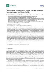
ApplyingThis variable geometry diffuser technique significantly increases therange operating range of the compressor. makes the impeller to work stably in a much wider mass flow than operating Applying variable geometry diffuser technique significantly increases the operating range of the compressor. This makes the impeller to work stably in a much wider mass flow range than operating range of a conventional fixed geometry compressor with the same impeller. Since the performance of compressor. This makes the impeller to work stably in a much wider mass flow range than operating range of a conventional fixed geometry compressor with the same impeller. Since the performance the impeller is independent of the diffuser, this technique can be used to study the performance of a of range of a conventional fixed geometry thecan same impeller. Since the performance ofof a thenew impeller is independent of the diffuser, this technique bethe used to study the performance impeller at the design process andcompressor improve thewith accuracy of matching between the impeller theimpeller impeller is independent ofconditions the diffuser, this technique can be to study the performance of a new process and improve the accuracy ofused the matching between the impeller and diffuser at in the the design operating in question. new impeller at the design process and improve the accuracy of the matching between the impeller and diffuser in the operating conditions in question. Although closing the diffuser significantly extends the stable operating range of the compressor and diffuserthe in the operating conditions in question. by shifting surge line to the lower mass flowextends rates, but at low mass flowofrates increases Although closing the diffuser significantly theworking stable operating range the compressor Although angle closingatthe diffuser extends stable operating range of the compressor incidence thethe impeller leading Figure 12 shows themass pitch-averaged spanwisethe bythe shifting the surge line to lowersignificantly mass flowedge. rates, butthe working at low flow rates increases by shifting the surgeincidence line to theangle loweratmass flow rates, but working at low mass operating flow rates points increases distribution the impeller edge six different at incidence angleofatthe the impeller leading edge. Figure 12leading shows the pitch-averaged spanwise distribution the incidence angle at the impeller leading edge. Figure 12 shows the pitch-averaged spanwise max. As shown 2, operating points of six 1 todifferent 5 are foroperating the “Closed 2°” at case from choke to of 0.9N the incidence angleinatTable the impeller leading edge points 0.9N max . As shown distribution of the incidence angle atpoint the impeller leading edge six “Closed different4°” operating points at ◦ surge, respectively, and the operating 6 is the choke point of the case. As the mass in Table 2, operating points of 1 to 5 are for the “Closed 2 ” case from choke to surge, respectively, 0.9N max. As shown in Table 2, operating points of 1 to 5 are for the “Closed 2°” case from choke to flow incidence mid-span This4rise of theAs incidence angle thethe ◦ ” case. and thedecreases, operatingthe point 6 is theangle choke point ofincreases. the “Closed the mass flowdecreases decreases, surge, respectively, and the operating point 6 is the choke point of the “Closed 4°” case. will As the mass stability of the tip region of the impeller leading edge to the point that flow separation happen incidence angle mid-span increases. This rise increases. of the incidence the stability of the tip flow theand incidence angledrop mid-span riseangle of thedecreases incidence angle decreases in thedecreases, tip region, a sudden of the incidenceThis angle happens at spans of above 90%the in region of the impeller leading edge to the point that flow separation willflow happen in the tip region, and stability of the tip region of the impeller leading edge to the point that separation will happen operating point 2, which is at 1.82 kg/s mass flow rate. a sudden drop of the incidence angle happens at spans of above 90% in operating point 2, which is in the tip region, and a sudden drop of the incidence angle happens at spans of above 90% in at 1.82 kg/s mass flow rate. is at 1.82 kg/s mass flow rate. operating point 2, which
Figure 12. Pitch averaged spanwise distribution of incidence angle at leading edge of the impeller. Figure Pitchaveraged averagedspanwise spanwise distribution distribution of edge ofof thethe impeller. Figure 12.12.Pitch of incidence incidenceangle angleatatleading leading edge impeller.
Energies 2017, 10, 682
12 of 15
Table 2. Different operating points shown in Figures 12 and 13.
Operating Point
OP1
OP2
OP3
OP4
OP5
OP6
Mass flow rate Diffuser setting
2.03 Closed 2°
1.96 Closed 2°
1.90 Closed 2°
1.82 Closed 2°
1.77 Closed 2°
1.74 Closed 4°
Energies 2017, 10, 682
12 of 15
Figure 13 shows the pitch-averaged spanwise distribution of the relative Mach number at the 13 shows the pitch-averaged spanwise distribution of the relative Mach number at the tip tip region ofFigure the impeller leading edge superimposed by the streamlines for the mentioned operating region of the impeller leading edge superimposed by the streamlines for the mentioned operating points. As we can see, by an increase of the incidence angle due to the decline of the mass flow, points. As we can see, by an increase of the incidence angle due to the decline of the mass flow, the the tip region becomes andflow flow recirculation vortex emerges. theflow mass flow tip region becomessignificantly significantly unstable unstable and recirculation vortex emerges. As theAs mass decreases further, the vortex grows and impinges the lower spans. decreases further, the vortex grows and impinges the lower spans.
13. Pitch-averaged spanwise contour of the relative Mach number at tip of the impeller leading Figure Figure 13. Pitch-averaged spanwise contour of the relative Mach number at tip of the impeller leading edge superimposed with streamlines. edge superimposed with streamlines.
As the performance of the impeller is independent of the diffuser, at each speed there is a critical Table 2. Different operating shown in Figures 12 andand 13. flow separation mass flow rate below which the impeller tippoints region will become unstable emerges, regardless of the diffuser setting or the stage-wide working condition (such as choke or Operating Point at operating OP1 points below OP2 the critical OP3mass flowOP4 OP5might be working OP6 surge). Although rate, the stage stably closing at the region may1.77 damage the impeller Massby flow rate the diffuser, 2.03 the flow separation 1.96 1.90impeller tip 1.82 1.74 Diffuser setting bladeClosed 2◦ Closed 2◦ Closed 2◦ Closed 2◦ Closed 2◦ Closed 4◦ due to increasing fatigue. 4. Conclusions
As the performance of the impeller is independent of the diffuser, at each speed there is a this rate work,below a variable diffuser vane was to become improve unstable the operating and critical massInflow which the impeller tipemployed region will and range flow separation performance of a high pressure ratio centrifugal compressor. This study employed steady-state emerges, regardless of the diffuser setting or the stage-wide working condition (such as choke or numerical simulations using Reynolds-averaged Navier-Stokes equations. Different diffuser vane surge). rotation Although at operating points below the critical mass flow rate, the stage might be working angles in a range from −6 to +6 were used to examine the effects on the performance of the stably by closing the the flowcan separation at theasimpeller compressor. Thediffuser, main conclusions be summarized follows. tip region may damage the impeller due to increasing blade fatigue. 1.
A variable vaned diffuser can significantly improve the operating range of centrifugal compressors. The effects of a variable vaned diffuser on high pressure ratio centrifugal compressors are 4. Conclusions verified. The stable operating range extended at different pressure ratio levels. There is an
In this work, a variable diffuser vane was employed to improve the operating range and performance of a high pressure ratio centrifugal compressor. This study employed steady-state numerical simulations using Reynolds-averaged Navier-Stokes equations. Different diffuser vane rotation angles in a range from −6 to +6 were used to examine the effects on the performance of the compressor. The main conclusions can be summarized as follows. 1.
A variable vaned diffuser can significantly improve the operating range of centrifugal compressors. The effects of a variable vaned diffuser on high pressure ratio centrifugal compressors are verified. The stable operating range extended at different pressure ratio levels. There is an increase of 30.0% in the operating range of the current case for pressure ratios between 5.0 and 6.0. At higher
Energies 2017, 10, 682
2.
3.
4.
5.
13 of 15
rotational speeds, the main contributor to range extension is the shifting of the surge line to lower mass flow rates, which is due to the closing of the diffuser. At lower rotational speeds, changing the angle of diffuser vanes has minimal impact on the surge mass flow rate while it significantly shifts the choke line. At medium rotational speeds, both surge and choke lines shift by changing the diffuser vane angle. Thus, both contribute to extending the operating range. A variable vaned diffuser has a significant impact on the compressor’s efficiency. At higher rotational speeds, the choke mass flow of the diffuser is matched by that of the impeller. Thus, opening the diffuser at these speed neither shifts the choke line nor improves the efficiency. At lower rotation speeds, however, the impeller and diffuser are not matched and choking happens at the diffuser. Because of this, opening the diffuser extends the operating range by shifting the choke line to higher mass flows and increases the efficiency of the stage by up to 4.5% at 0.8Nmax by improving the matching between impeller and diffuser. The impeller performance is independent of the modification in diffuser vane angle. For every rotation speed, the component performance of the impeller is a consistent curve even for diffusers with different vane angles. A change in the diffuser settings did not change the flow conditions at the impeller exit. Centrifugal impellers coupled with variable diffusers are able to operate in a wide range of mass flow rates. This is proposed as a general method to study the behavior of the impeller over a wide range of mass flow rates. By applying this approach, a critical point in the operating range of the impeller from stability was found. At each rotation speed, there is a certain mass flow rate for the impeller where the incidence angle at the impeller leading edge reaches a critical point. Because of the high incidence angle, instability and separation vortexes will arise in the near-tip region of the impeller as the mass flow rate decreases. This critical point is independent of diffuser settings and stage-wide working conditions such as choke or surge, which means even when the stage is in a stable condition there might be large separation vortexes at the near-tip region of the impeller. The instability in the impeller will grow larger with a further decrease in the mass flow rate.
Acknowledgments: We would like to thank the National Natural Science Foundation of China (Grant No. 51176087) for supporting this research. Author Contributions: Mohsen Ebrahimi acquired the data and wrote the paper; Qiangqiang Huang, Xiao He and Xinqian Zheng revised the paper and offered useful suggestions to write the paper; in addition, Qiangqiang Huang assisted in analyzing the data. Conflicts of Interest: The authors declare no conflict of interest.
Nomenclature A h . m . mc . ms Ma Nmax P T r rk y+ Z γ η π ω
passage area enthalpy mass flow rate choke mass flow rate surge mass flow rate Mach number maximum rotational speed of the impeller pressure temperature distance in the radial direction degree of reaction normalized wall distance number of blades specific heat ratio = 1.4 (constant) for air in this paper total-to-total isentropic efficiency total-to-total pressure ratio loss coefficient
Krain, H. Review of Centrifugal Compressor’s Application and Development. J. Turbomach. 2005, 127, 25–34. [CrossRef] Bents, D.J.; Mockler, T.; Maldonado, J.; Harp, J.L., Jr.; King, J.F.; Schmitz, P.C. Propulsion System for Very High Altitude Subsonic Unmanned Aircraft; NASA Technical Briefs DRC-98-61; NASA Lewis Research Center: Cleveland, UT, USA, 1998. Bettner, J.L.; Blandford, C.S.; Rezy, B.J. Propulsion System Assessment for Very High UAV under ERAST; NASA CR-195469; NASA: Cleveland, UT, USA, 1995. Rodgers, C. Turbocharging a high altitude UAV C.I. engine. In Proceedings of the 37th Joint Propulsion Conference and Exhibit, Salt Lake City, UT, USA, 8–11 July 2001; American Institute of Aeronautics and Astronautics: Reston, VA, USA, 2001. Rodgers, C. Flow Ranges of 8.0:1 Pressure Ratio Centrifugal Compressors for Aviation Applications. In Proceedings of the ASME Turbo Expo 2005 Parts A and B, Reno, NV, USA, 6–9 June 2005; Volume 6, pp. 801–811. Cumpsty, N.A. Compressor Aerodynamics, 2nd ed.; Krieger: Malabar, FL, USA, 2004. Rodgers, C.; Brown, D. A Performance Autopsy of Three Centrifugal Compressors for a Small Gas Turbine. In Proceedings of the ASME Turbo Expo 2010: Power for Land, Sea, and Air (Volume 5: Industrial and Cogeneration; Microturbines and Small Turbomachinery; Oil and Gas Applications; Wind Turbine Technology), Glasgow, UK, 14–18 June 2010; pp. 239–247. Zheng, X.; Zhang, Y.; Yang, M.; Bamba, T.; Tamaki, H. Stability Improvement of High-Pressure-Ratio Turbocharger Centrifugal Compressor by Asymmetrical Flow Control—Part II: Nonaxisymmetrical Self-Recirculation Casing Treatment. J. Turbomach. 2012, 135, 21007. [CrossRef] [PubMed] Li, P.-Y.; Gu, C.-W.; Song, Y. A New Optimization Method for Centrifugal Compressors Based on 1D Calculations and Analyses. Energies 2015, 8, 4317–4334. [CrossRef] Moosania, S.; Zheng, X. Comparison of Cooling Different Parts in a High Pressure Ratio Centrifugal Compressor. Appl. Sci. 2016, 7, 16–28. [CrossRef] Whitfield, A. Review of Variable Geometry Techniques Applied to Enhance the Performance of Centrifugal Compressors. In Proceedings of the International Compressor Engineering Conference, West Lafayette, IN, USA, 25–28 July 2000; pp. 63–70. Simon, H.; Wallmann, T.; Mönk, T. Improvements in Performance Characteristics of Single-Stage and Multistage Centrifugal Compressors by Simultaneous Adjustments of Inlet Guide Vanes and Diffuser Vanes. J. Turbomach. 1987, 109, 41–47. [CrossRef] Salvage, J.W. Development of a Centrifugal Compressor With a Variable Geometry Split-Ring Pipe Diffuser. J. Turbomach. 1999, 121, 295–304. [CrossRef] Ziegler, K.U.; Gallus, H.E.; Niehuis, R. A Study on Impeller-Diffuser Interaction—Part I: Influence on the Performance. J. Turbomach. 2003, 125, 173–182. [CrossRef] Huang, Q.; Zheng, X. Potential of variable diffuser vanes for extending the operating range of compressors and for improving the torque performance of turbocharged engines. Proc. Inst. Mech. Eng. Part D J. Automob. Eng. 2017, 231, 555–566. [CrossRef]