Efficient and Reusable Offset Cancellation Method Implemented in CMOS Design B. Mrković, I. Broz and D. Ribić Systemcom Ltd., Design Center Maksimirska 120, 10000 Zagreb, Croatia Phone: (+385 1) 2339 592 Fax: (+385 1) 2339 590 E-mail:
[email protected],
[email protected],
[email protected]
Abstract – An efficient and reusable offset cancellation method is presented, applicable for all amplifier structures with input resistances. The offset is cancelled with the current injected into amplifier's split input resistances. To keep the compensation range equal over the all working conditions, the compensation current is generated using the resistor from the voltage reference, matched with the amplifier’s resistors. The compensation current value is generated with the simple IDAC structure, controlled by SAR or even a simple counter, depending on the available compensation time. Such approach requires a simple circuitry and it is very easy to implement. The effect to compensated amplifier’s noise and linearity is low and controllable, while the effect to the gain accuracy doesn’t exist. Additional advantage of using current instead of voltage for compensation is in insensitivity to interferences. By using a simple circuit for offset cancellation range adjusting, the proposed method becomes reusable.
I. INTRODUCTION For a resistive gain chain, especially with a large required gain, offset error is, by nature, an issue which should be solved for correct and acceptable overall functionality. Depending on the requirements for the overall gain, as well as the remaining offset error at the output, offset cancellation points (loops) can be put on one or more places. The main purpose of the offset cancellation is to cancel various offsets coming from input, from the modules inside the gain chain, etc. resulting in minimum remaining offset error at the output without affecting the signal dynamic across the gain stages.
II. PRINCLE OF OPERATION Among several possibilities for offset cancellation implementation, the simple one was chosen and modified. Offset cancellation is realized by differential current injection into split stage’s input resistors. The compensation current is generated from a bandgap voltage reference and determined by an appropriate resistor value. To keep the offset cancellation ranges invariable over all working conditions, the stage’s resistors and the resistor in the voltage to current converter block should be matched. Although such approach needs a very simple circuitry easily implemented, it is accurate, robust, and also insensitive to interferences. In addition, with such an implementation, the influence to the gain stage’s linearity and noise is very small and quite acceptable.
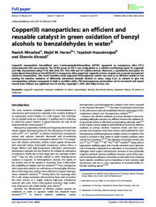
Fig. 1. Offset errors and cancellation
Figure 1. shows the simplified offset cancellation scheme. The stage’s offset error is emulated by an independent voltage source VOFF and the remaining offset error from the previous stages by VOFF_P. The offset error at the output caused by VOFF and VOFF_P, which should be compensated, is represented by VOE. The needed compensation current is represented by IOC and the resulting offset compensation voltage by VOC. Such approach has additional advantages: easy compensation polarity change; meaning sign implementation which actually increases compensation resolution for one bit; and secondly easy adjustment. As the zero value is defined, it is enough to take care of the necessary compensation range only. Additional important advantage of the presented approach is that the ratio R1B/(R1A+R1B) defines the compensation current value and, assuming the real current source, affects the linearity of the signal path. It is easy to calculate current needed to compensate the known offset error at the output VOE:
R1 A ⋅ R1B ⋅ I OC R1 A + R1B R VOE = VOC ⋅ 2 R1B R VOE = 2 ⋅ 1 A ⋅ I OC ⋅ R2 R1
VOC = 2 ⋅
(1) (2) (3)
With the known offset error at the output, the appropriate compensation current is:
I OC =
VOE ⋅ R1 2 ⋅ R1 A ⋅ R2
(4)
In case of a small stage’s offset error, the offset cancellation loop can be implement on a cascade of gain stages. With gainCR as the gain of following cascade stages (cascade without the first stage), the necessary compensation current is:
I OC =
VOE ⋅ R1 2 ⋅ R1 A ⋅ R2 ⋅ gainCR
With resistor matching and by keeping resistance ratios constant, stable compensation range over all working conditions is achieved. The offset error at the stage output is:
VOE = (VOF _ P ⋅ gain + VOFF _ OA ⋅ (1 + gain ))
(8)
(5) where
The implemented offset cancellation loop is shown in more detail by Figure 2. The offset cancellation current is generated with IDAC (current mode digital to analog converter) controlled by SAR (Successive Approximation Register) logic, but a simple counter is quite acceptable, in many cases. IDAC is followed by a simple current range block (simple current mirror) and a simple differential current driver with polarity control. Such approach allows us to use practically the same loop for different application points after correct adjustment of the current range block, for fully differential and for single ended outputs, as well.
gain =
R2 R1 A + R1B
(9)
For the offset cancellation range and the remaining offset error calculation, the maximum gain value is important. The calculated value defines the output offset cancellation range. For the real system, this value should be slightly enlarged, multiplied with some kOC (1.05-1.1), because of temperature dependency, uncalculated mismatch (squared ratio), gain errors etc. After offset cancellation, the remaining offset error at the gain chain output is:
VOE _ REM =
kOC ⋅ max(VOE ) + VOFF _ COMP 2n − 1
(10)
where n is the IDAC’s resolution, in bits and kOC·max(VOE) is the cancellation range at the output.. The simulation results show that calculations were quite correct. Fig. 2. Offset cancellation loop block scheme
III. IMPLEMENTATION
With known offset errors for the used OPAMP and comparator (simulated using Monte Carlo analysis with process and mismatch model variation and maximum available number of samples), we are able to calculate the real offset error and the required offset cancellation range. For calculation, the worst case is assumed: • offset errors are used as positive (polarities of offset errors are defined in such a way that the resulting offset error at the stages’ outputs are maximal and positive) • the maximal gain is used in case of variable stage’s gain At the beginning, since:
I OC ≈
VBG RVI
(6)
A. General Information The presented offset cancellation loop and gain stage were part of front-end, organized as a cascade of stages with a very high overall gain. The circuit was designed, simulated and verified in the 350 nm technology across the process corners and the temperature range. The design of circuit can be processed in any available mixed–signal technology with necessary re-calculations and optimizations due to the specific characteristics of the technology. To save space and to keep a clear picture, only some of the schematics will be shown. The top level schematic is similar to the offset cancellation block scheme (Figure 2.). The used R-2R MOS IDAC architecture is well known and the corresponding schematic will be avoided also. In the design, all resistors have the same unity resistance to achieve matching and R1A and R1B are equal.
where VBG is the bandgap (or any reference voltage), than:
VOE 2 ⋅ R1 A ⋅ R2 ≈ VBG RVI ⋅ R1
B. Voltage to Current Converter
(7) The voltage to current converter (Figure 3.) is simple and well known circuit, with the bandgap voltage as the
reference. Voltage-to-current converter uses a resistor with the same unity resistance as the resistors in affected gain stages. Resistances should be matched in the layout to avoid the changes of the compensation ranges over the process variations and working conditions. In case of restrictive area requirements, in case when multiple offset cancellation loops are required, the voltage-to-current converter can be implemented as common, shared between different offset cancellation loops.
to change the output current polarity. Although directly connected to the signal path, because of the differential, symmetrical structure connected to the differential signal path, the impact to the signal being processed is minimal. Leakage does not present a problem due to the fact that the differential signal is affected in both planes acting as a common signal.
Fig. 3. Voltage to current converter
C. Comparator Fig. 5. Differential current driver
Regarding to requirements, for different offset cancellation loops, different comparators should be used. The used comparator was optimized for fully differential input signals. As the remaining offset error always depends on the used comparator’s offset error, regardless to compensation resolution and range, the comparators were also optimized regarding to their own offset error. D. IDAC For the described offset cancellation loop a simple, but optimized, 8 bit R-2R MOS IDAC was chosen. The IDAC is controlled by a SAR regarding to the limited time available for the compensation. The SAR was implemented with the polarity control (sign, equivalent to additional bit). The compensation range is 8 bits with the sign (polarity, equivalent to 9 bits resolution).
IV.VERIFICATION Offset cancellation in real gain chain was simulated over all working conditions, using ideal voltage sources for particular offset error emulations. Working conditions are all process corners; temperature range: -40 +125ºC; power supply voltage: 3.2 – 3.6V and bias currents (operational amplifiers): 93 – 107% of the nominal values. Polarities of offset error voltage sources were chosen to give the worst possible errors over gain chain stages.
E. Current Range Blocks The current range block (Figure 4.) is a simple current mirror, used for a simple offset cancellation range adjustment. Such an approach allows us to reuse the same offset cancellation loop, even to share the same voltage to the current converter for different loops. Fig. 6. Offset cancellation voltage and current ranges, the worst case
Fig. 4. Current range block
F. Differential Current Driver Differential current driver (Figure 5.) is a single-ended to fully-differential current converter, having the possibility
Figure 6. shows the offset cancellation voltage (VOC) and current (IOC) over all IDAC’s input values. The nominal and the worst cases (min and max) over process corners and working conditions are shown. Maximal values actually represent compensation ranges. As expected, regarding to technological resistor’s value variation, the current range is also changed. With required resistors matching, the voltage range is acceptably stable. As the offset error is practically constant over all working conditions for any particular corner, the achieved range stability fit our needs.
TABLE I Offset cancellation voltage changes, all cases
OC voltage range, all cases Min. [-%] Nominal [mV] Max. [+%] -2.39 78.8924 3.46
Fig. 9. The output voltage VOE, during offset cancellation, all cases, positive offset error
Figures 10. and 11. show the output voltage (VOE) for the case with the gain stage which performs fullydifferential to single-ended conversion, both cases regarding to the offset error polarity.
Fig. 7. Influence to the gain stage linearity error
Figure 7. shows the signal path linearity error caused by the offset cancellation loop, for full signal swing, with its nominal and the worst cases over all process corners and working conditions. TABLE II Linearity error over all working conditions
Linearity error, all cases Nominal [%] Max. [%] ± 0.018 ± 0.022
Fig. 10. The output voltage VOE, single-ended output, during offset cancellation, all cases, negative offset error
Figure 8. shows the output voltage (VOE) during the offset cancellation with the IDAC controlled by the SAR logic, over all process corners and working conditions. Offset errors were chosen to cause maximal negative offset errors at the output.
Fig. 11. The output voltage VOE, single-ended output, during offset cancellation, all cases, positive offset error
V. CONCLUSION Fig. 8. The output voltage VOE, during offset cancellation, all cases, negative offset error
Figure 9. shows the output voltage (VOE) during the offset cancellation with the IDAC controlled by the SAR logic, over all process corners and working conditions. Offset errors were chosen to cause maximal positive offset errors at the output.
An efficient and reusable offset cancellation method is presented. It is applicable for all amplifier structures with input resistances. Reuse of the proposed offset cancellation method is simple. The compensation current range should be calculated and the current range block (simple current mirror) should be adjusted after a correct splitting of stage’s input resistors (regarding to acceptable effect to the linearity error). It is enough for almost all applications in resistive gain stages with differential inputs.
In the case of smaller offset errors, or in the case of a single-ended input architecture, some simplifications of the presented circuits are possible.
REFERENCES [1] D. M. Binkley, Tradeoffs and Optimization in Analog CMOS Design, A John Wiley & Sons Ltd. Chichester, West Sussex, England, 2008. [2] R. J. Baker, CMOS Circuit Design, Layout and Simulation 2nd Edn., Wiley-IEEE Press, New Jersey, 2005. [3] B. Razavi, Design of Analog CMOS Integrated Circuits, International Edition, McGraw-Hill, 2001