{em, akmalino, jxs}@cs.umb.edu. Department of Computer Science. University of Massachusetts, Boston .... may transform the input data to a new form before passing it to .... mines if next plugin is to be executed; if the validation fails, the.
Matilda: A Distributed UML Virtual Machine for Model-Driven Software Development Manikya Madhu Babu Eadara, Adam Malinowski and Junichi Suzuki {em, akmalino, jxs}@cs.umb.edu Department of Computer Science University of Massachusetts, Boston Abstract. This paper describes a distributed UML virtual machine, called Matilda, which allows developers to design their applications as UML models and directly execute the models. Matilda accepts the UML models that developers define (class and sequence diagrams), validates them against the UML metamodel, constructs a Java abstract syntax tree (JAST) that corresponds to the user-defined models, and executes Java byte code generated from the JAST. The architecture of Matilda is designed as a pipeline (or sequence) of plugins. Different plugins implement different functionalities in Matilda, such as importing UML models, validating UML models and constructing a JAST. The pipeline architecture allows Matilda to flexibly configure its structure and behavior by replacing a plugin with another one or changing the order of plugins. Also, Matilda’s pipeline can be distributed. Matilda can spread plugins over multiple hosts in the network and seamlessly connect them to form a pipeline. This improves Matilda’s performance by distributing its workload to different hosts. It also enables distributed model-driven development in which developers can build, transform, deploy and execute UML models at physically distributed places. This paper overviews Matilda’s architectural design and describes implementation details of its major plugins. Keywords: Model-driven development, UML virtual machine 1. INTRODUCTION Software modeling is becoming a critical process in software development, and modeling technologies have matured to the point where they can offer significant leverage in all aspects of software development [1]. Models expressed in a well-defined notation are a cornerstone to understanding systems for enterprise-scale solutions [7]. The current state of this practice employs the Unified Modeling Language (UML) as the primary modeling notation. The UML models help software developers and system designers to structure and focus their thinking and develop a solution with out worrying about the implementation details [3]. However, the transformation from UML models to the final implementation is manually performed in many software development projects by the programmers. UML models are given by the system architects and are interpreted by programmers, who write code to implement the models. The manual interpretation of the design artifacts, like UML models, to write code requires human intervention and has its disadvantages. Over time, with changes applied to the code and not to the UML models, it becomes difficult to trace the code back to its model. This results in semantic gap between code and the models. The manual interpretation of the model to write code is also time consuming and need to be repeated every time there is a change in the design to add or modify functionality. For example, a design change or additional functionality requested by the user, late in the development process, will exponentially increase the programming effort to implement the
change in the code. This results in the longer turnaround time, and more expensive software development. Matilda uses the MDA approach to software development, which is a conceptual framework provided by OMG to express models, model relationships, and model-to-model transformations. With Matilda, a computationally complete UML model can be used to generate final code. A developer can focus on the structure and logical flow of the software under development and leave the implementation to Matilda. Using Matilda to develop software will result in seamless mapping between UML models and the code that implements the model avoiding traceability issues and semantic gaps between code and models. With this approach, by eliminating the manual interpretation of models to write code, we can have faster turn around time and less expensive software development. Matilda is a model-driven development platform that accepts the UML 2.0 class diagrams and sequence diagrams as input. The input model will be represented as XMI documents. The XMI is parsed to build in-memory UML models. The inmemory models are then checked against the UML metamodels for syntax and semantic correctness. The UML models are also checked for computational completeness and conformance with UML Profiles applied to the models. The UML models are then mapped to the Abstract syntax tree from which the code is generated. Matilda uses the pipeline architecture and the functionality of the virtual machine like validation, code generation is provided by plug-ins. The pipeline architecture provides flexibility to add new plug-ins to support new functionality, for example, validating a new UML profile. The model validation, integration and code generation functions of the virtual machine takes lot of processing power for any non-trivial software development effort. The Matilda is designed to be distributed. The plug-ins that provides the functionality need not be all available on the design host and hence these functions can be distributed across the network host and balance the load. This paper overviews Matilda’s design principles and architectural design, and describes implementation details of major plugins. In order to present how developers use Matilda, this paper also show an example application developed with Matilda. The structure of this paper is organized as follows. Section 2 describes the design principles of Matilda. Section 3 compares Matilda with related work. Sections 4 and 5 describe the architectural design and implementation of the Matilda. Section 6 describes an example application developed with Matilda.
2. DESIGN PRINCIPLES Flexible One of the foremost design principles of the Matilda is to be flexible to handle transformations of various types of models. Matilda is designed to be metamodel driven, means the changes in the input model will not affect the functionality as long as the model is verified against the metamodel. The metamodel acts as the guide for the input models. Any model that is developed in compliance to the metamodel can be a valid input to Matilda. This gives flexibility to customize or extend the models instead of adhering to a strict set of model syntax. Modular and loosely coupled The functionality of Matilda is build into reusable components to enable maximum reuse. The functionality in Matilda naturally decomposes into independent steps of a sequence of model verifications and transformations. This facilitates developing the verification and transformation functionality as independent programming units. To enable the reuse of the individual components, each component must work independently with minimum dependence on the other components. This will facilitate the reuse of the component at any stage of the processing. The components are designed to be loosely coupled and modular to maximize reuse. Configurable The order of the plugins as well as the functionality of the plugins must be configurable. This will enable us to build a broad range of model transformations. Because the individual software components are loosely coupled and the software components perform a well-defined function, the order of the components can be changed as required by the application at runtime. The individual programming units must have a standard interface to the system. This will enable us to focus on the new functionality, while developing the new components, without worrying about the new component’s interface to the entire system. With a standard interface, new components can seamlessly integrate with the existing system and enables maximum reuse of the functionality. Transparently Distributed As the model transforms from PIM to ISM, we need to attach the platform specific details on the deployment host to the models. The most common example is to generate the executable code multiple heterogeneous deployment hosts rather than the development host. This requires Matilda to be transparently distributed – means, each component must perform its function, including accessing shared global state information, without the explicit knowledge of the whereabouts of the next software component. The underlying platform must support take care of marshalling the information between different hosts transparent to the participating components. In programming terms, no infrastructure code in the functionality components.
vendor. This means that the designer has to learn the proprietary action specification language syntax every time she uses a new modeling tool. This involves a steep learning curve and will increase the development time. Another disadvantage of using xUML is there is no interoperability between two vendors of xUML. The xUML diagrams specified using one vendor’s language cannot be interpreted without significant changes by the other vendor’s software. Matilda on the other hand is compliant with UML2.0 and uses the sequence diagrams for behavior modeling. The UML diagrams can be drawn using any UML2.0 compliant tool and can be imported into Matilda for further processing. Furthermore, xUML tools are not designed to be distributed. The xUML tools cannot emit executable code to the deployment hosts directly. The tools like Gen2J, Jamda and XDoclet take a code generation approach of taking a UML diagram to the source code directly. Although code generation is a requirement, it is not the only requirement. The code generators typically use proprietary templates as input in addition to the UML diagrams. The templates are specific to the code generator and do not capture the domain knowledge of the solution. Although many of the code generators claim to be complaint to MDA, they do not develop the use of metamodels and do not perform the model transformations. The code generators directly take the UML diagram to the executable/source code. This results in an inflexible architecture which need major changes to support new technologies. The code generators mostly use proprietary templates, which are difficult to understand and master. Unlike code generators, Matilda is metamodel driven and is flexible to change. Further none of the code generators actually use standardized methods for behavior modeling. Most of them actually generate stubs to be filled in by the programmers and can achieve up to a maximum of 85% automatic code generation. Matilda on the other hand follows a Model-Only approach and generates 100% of the code from the model – in a true MDA spirit. Matilda sets itself apart from the rest of the work primarily by the use if metamodels to verify the models and then by the use of model transformations in a platform independent way. Using metamodel allows the change in the input models without changing the code that processes it. Another key difference is that none of the existing work is geared up for the development/deployment on distributed machines. Matilda is designed from ground up to be distributed. The functionality is segregated and the components can communicate across development hosts, enabling teamwork during development and cross platform deployment after development. Matilda uses the sequence diagrams to describe the behavioral modeling instead of vendor specific action semantics and hence is more open for future extensions and integration with 3rd party code generators and code optimizers. 4. ARCHITECTURAL DESIGN
3. RELATED WORK The xUML process involves the creation of executable UML models with the UML diagrams. The xUML uses state charts and action semantics for behavioral modeling. UML diagrams are enriched with the action semantics-compliant Action Specification Language (ASL) for behavior modeling [3]. The action semantics extension to UML defines the underlying semantics of Actions, but does not define any particular surface language. The actual language is provided by the vendor of the xUML tool like iUML from Kennedy Carter. The semantics of the ASL are defined but the syntax of the language varies from vendor to
Matilda is based on the pipes and filters architecture pattern with the majority of the functionality being provided by the plugins/filters. The Pipes and Filters architectural pattern provides a structure for systems that process a stream of data[2]. Each processing step is encapsulated in a filter component. Data is passed through pipes between adjacent filters. Recombining filters allows to build families of related filters [2]. The pipeline design pattern is best suited when the system naturally decomposes into several independent steps and the requirements are likely to change. This architecture allows us to enhance the
system by substituting new filters for existing ones or by recombining the steps into a different communication structure.
pipeline to access the remote plugins as if they are located locally requires that the remote pipeline has access to all the configuration of the plugins, as the local pipeline has, and to provide an interface to the remote pipeline to access the plugin. Blackboard. The general assumption of pipeline is that if two steps are not adjacent, then they share any information. However, this assumption severely cripples the functionality in accessing the global data. Moreover, the output of one filter cannot be routed to multiple filters. To overcome this design challenge, Matilda implements the black board in the pipeline. Black board keeps the global data that is common to the multiple plugins. The black board acts as the messaging center between different plugins for exchanging state and configuration information. Another common draw back of conventional pipeline design pattern is lack of robust error handling since there is not global state information and often multiple asynchronous threads of execution exist in the system. This becomes more complicated when the plugins are distributed across different network hosts in a distributed pipeline. The black board addresses this by maintaining the state information of the plugins on the blackboard and allowing more concrete error handling. Further, transactional integrity of shared data becomes a key issue when dealing with the distributed systems. The black board is distributed and transitionally secure by design which is explained in more detail in the implementation section. 5. IMPLEMENTATION.
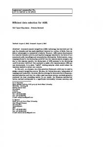
Fig.1 Class Diagram of Matilda
Filters/Plug-ins. The filters are the processing units of the pipeline [2]. A filter may enrich, refine, or transform its input data. In general, a transformation filter will enrich the model by computing new information from the input model and adding it to the output model. It may refine the model by concentrating or extracting information from the input model and passing only that information to the output stream like to a code generator. It may transform the input data to a new form before passing it to the output stream, like converting the input model in XML to an internal UML tree. It may, of course, do some combination of enrichment, refinement, and transformation. A validation filter will verify the input model against the input metamodel. The plugins/filters in Matilda are designed to be passive i.e. the underlying pipeline invokes the plugin based on the configuration rather than a plugin taking a proactive role and instantiating a processing action. Pipeline. The pipeline provides the framework for the operation of the filters. Different sources of input data exist and the pipeline takes care of routing the data between different filters. The pipeline has the information about the sequence of filters, the input and output data types of the pipelines. The key feature of the pipeline is that it is transparently distributed. This means that it’s the responsibility of the pipeline to transport data between the plugins, across hosts if necessary. This brings forth an important requirement of the underlying pipeline to expose its state and plugin information to the other pipelines. To enable a
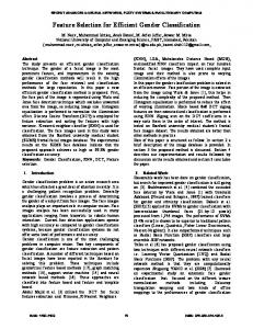
UML input models in Matilda are defined using UML2.0 class and sequence diagrams which is sufficient to describe both static and dynamic features for a subset of models. Other types of diagrams (state, activity) are currently not supported in the UML-VM specification. Class diagram defines structure and sequence diagrams define dynamic behavior of a model. Mapping of UML-VM model to a Java model is as follows: UMLVM class diagram maps to Java type, member and method declarations whereas the UML-VM sequence diagrams map to Java method implementations. Due to these and other restrictions on accepted UML models, user models must satisfy a set of rules to pass the model validation process and to be allowed for subsequent translation to executable code. UML-VM profile is specified in which a subset of UML2.0 for input models is defined, i.e. which elements are supported and understandable by the profile validator and which do not pass the validation. The profile also specifies constraints imposed on UML elements and extensions to UML metamodel in form of stereotypes and tags. There are at least five major groups of plugins required in the UML-VM pipeline configuration to execute UML models: (1) model loader plugins that read user-supplied models in given formats and convert them to internal structure recognizable by one or more subsequent plugins; (2) UML superstructure validator plugin to validate a model consistency according to the standard metamodel specification; (3) profile validation plugin that narrows down the pool of accepted models to be passed to the (4) executable code generation plugin that maps model to executable code or an intermediate language from which executable code can be generated, and (5) execution plugin to initialize runtime environment and execute generated code. Clearly, there is a unidirectional, synchronized data flow between subsequent plugins, and each plugin reads some data from the the black board (with an exception of the first plugin), processes it and may or may not place new data back on the common stor-
age space. There also is possible (6) group of transformation plugins in the chain that can be specialized either in transforming between two different serialization formats, between different metamodels, or different intermediate languages. Model Loader
XMI
UML Meta Model Validator
UML Model
UMLVM Profile Sequence Diagram Validator
UMLVM Profile Class Diagram Validator
UMLVM Profile Integrated Diagram Validator UMLVM Profile Validation
Class Diagram to JAST Mapper
Verified UML Model
Sequence Diagram to JAST Mapper
JAST
UML to AST Mapping
JAST Validator
Java Executor
Byte Code Black board
Fig.2 Process Diagram of Matilda
Having transformation plugins ensuring compatibility between different metadata, one can realize that the chain of specialized modules in the pipeline can grow large in size as long as data required to read and write is available and compatible for every plugin and that they are executed in proper order. Each group of plugins has specialized subgroups of plugins that can be interchanged seamlessly given proper configuration. There are different subgroups of specialized plugins possible for loading a model from different formats (XMI2.0, other versions of XMI, Rational, UML graphical tools not fully compliant with XMI), profile validation for different constraints and extensions (UMLVM, EJB, CORBA, C/C++, EAI, business process profiles), code generation plugins for different executables and environments (Java, .NET, i386, Solaris), or simulators. Different runtime plugins can also be substituted by debugger plugins. Although there is generally only one metamodel validation plugin in a single configuration, there can be many profile validation plugins connected in series for models with a higher features specialization. However, by supporting complex mod-
els defined with use of additional profiles, code-generator plugin may need to be extended to support a new framework. In the current version of UML-VM there are five main plugins in configuration to provide execution of a subset of UML models as stand-alone, single-threaded Java console applications. The first plugin, ModelLoader, reads UML2.0 model serialized to XMI2.0 format that can be previously exported from a UML modeling tool (currently only Eclipse UML2 editor which is the lowest-level UML modeling approach), and it uses an internal XMI parser embedded in EMF to create a UML resource representing the UML model. The UML resource is conveniently accessible using open-source EMF UML2 API to query and operate on the UML model. If model serialization conforms to XMI2.0 and all profiles applied to the model are accessible within specified profile path, the model is successfully loaded. The loader plugin then places the UML2 model extracted from the resource in the black board storage to be available to other plugins. At this stage, the model is already an instantiated UML model, whether it is valid or not. The next plugin in the UMLVM pipeline, UmlMetamodelValidator, is the standard UML2.0 Superstructure [4] validator plugin. Because structural validation has already been implemented in EMF UML2 project, this plugin is essentially a wrapper over UML2Validator class, which is being invoked on every element of the metamodel instance and its parent meta-class. Result of validation determines if next plugin is to be executed; if the validation fails, the structural inconsistencies are logged and the pipeline stops. UmlMetamodelValidator does not alter the model in any way and it does not put any new data to the black board, it simply determines whether model is a valid instance of UML2.0 metamodel. The next, third, plugin in series is UmlvmProfileValidator that checks if the model, in addition to being a valid UML2.0 model, is also an acceptable UML-VM model, as specified in the UML-VM Profile. The most important reason behind this validation step is to determine whether the model is ready for processing by the fourth plugin in series that maps UML-VM model to Java model. Profile validation is achieved by traversing the model structure with an extended version of UML2 validator that implements both structural and semantic validation features of extended UML-VM metamodel. The plugin actually consist of three sub-plugins; one for class diagram, one for sequence diagram and one for integration of both, leaving space for supporting additional UML diagrams in the future. Similarly to the previous plugin, the profile validator does not generate any new data; it queries the model in a readonly manner, logs potential inconsistencies and/or allows for execution of the next plugin. The fourth major plugin configured in the pipeline is the code generation plugin. It generates executable Java byte-code indirectly; first by mapping a valid UML-VM model instance to an instance of Java metamodel, an abstract Java syntax tree (JAST) instance, then by generating executable code from the JAST instance. During the first step, UML model elements are becoming JAST node instances according to defined mapping rules. One UML element maps to many JAST nodes. Some mappings can be performed directly, for others parsing of Java expressions contained within UML model elements is required. During the mapping step, a syntactically correct JAST tree is instantiated using JAST API. Also, UML to JAST mappings are recorded in a data structure that can be latterly used by a model debugger for a reverse lookup. The mapping plugin actually consists of two sub-plugins: ClassDiagramToJast-
Mapper and SequenceDiagramToJastMapper, for the two types of diagrams. The former creates a new JAST with type (class and interface) declarations, member field and method declarations, and then it outputs a compilation unit for each type declaration. There are also stub method definitions created which are filled with blocks containing only the proper return statement. The latter module, SequenceDiagramToJastMapper, reads from black board previously created compilation units that are updated with method definitions mapped from each sequence diagram. If a sequence diagram for a given method does not exist, the JAST node for a method definition is left off just with a method body having a proper return statement. The reason for this approach is to be able to generate byte-code for the model and debug it before user completes all sequence diagrams. When the complete JAST representing user model is created, the second part of code-generation plugin (JastValidator) performs two traversals; first for JAST semantic analysis and second to generate Java byte-code and output class files. JastValidator is essentially a Java compiler back-end. Finally, the last plugin in the pipeline configuration, JavaExecuter, first reads-in the user model again to determine which class is executable (properly stereotyped), sets up the execution environment (JVM), feeds in class files and the model execution proceeds. 6. AN EXAMPLE APPLICATION Calculator model implemented in UML2.0 uses applied UMLVM profile and is a representative example for UML Virtual Machine executable model. Arithmetic expression is passed to the executable at runtime and result of calculation is printed out to console. The input arithmetic expression is given in reverse Polish notation. Summation, difference, division, multiplication and factorial operations are supported. Calculator uses objectoriented semantics and complies with the UML-VM profile, for it is a solid test case model for the UML Virtual Machine. Class Diagram. Class diagram is essential for UML modelers to communicate the model structure and is a required diagram for UML Virtual Machine to create model structure and namespace referred to by other diagrams integrated into the model. UML-VM class diagram is largely as defined by UML Metamodel specification, with some minor restrictions. A subset of EJB Profile for UML and UML-VM profile is applied to the model to impose those restrictions and provide additional information.
Fig.3. Class diagram of Calculator example
The class diagram for the calculator example is shown above. The calculator model has a central Calculator class with an execution entry (denoted by stereotype and a main method) to which input arithmetic expression is passed. Other type declarations within this class diagram are: Tokenizer class, Token interface, Operand to encapsulate a double value, abstract Operator and its five subclasses for calculating different arithmetic operations: PlusOperation, MinusOperation, MultiplyOperation, DivideOperation and FactorialOperation. Besides local variables and imported types, all member variables and methods referred to in the model are declared in the class diagram. UML attributes and associations are mapped to Java member variables. UML operations are mapped to method declarations with bodies containing only appropriate return statement. Typed names (classes, interfaces, attribute types, methods types) used in the diagram that are not defined in the package are fully qualified names. A subset of EJB extensions is applied to the model. For example stereotype may be used to denote that interface can include constant declarations (as opposed to UML interface). Sequence Diagram. Due to higher complexity of dynamic model features, sequence diagram has more rules and restrictions than the class diagram. There can be many sequence diagrams in a model for which they define dynamic behavior – one for each method declaration. The example of UML-VM sequence diagram below shows implementation of getNextToken() interaction declared in Tokenizer class for the calculator model. Interaction taking place is invoked by Calculator object (caller); the calling object is not given in the sequence diagram because potentially there may be many different callers to one diagram. In preceding interaction, first, the Calculator object initiates Tokenizer by passing arithmetic expression to it and Calculator makes subsequent calls to Tokenizer:getNextToken() inside a loop fragment, requesting processed tokens. The interaction results in tokens being returned that are either Operator or Operand instances. Tokenizer keeps track of the next token string to be processed. If the current token string is successfully recognized as an Operator by having a hash entry in operators map, the corresponding Operator is returned, for example FactorialOperator matching “!” string. If lookup is not successful, the token is assumed to be an Operand and it is parsed to a double value. The double value is then wrapped inside a new Operand object, and the token is returned back to the caller.
Fig.4. Sequence diagram of Calculator example
UML-VM diagrams are used in generic form, i.e. a sequence diagram for a particular interaction defines all possible alternatives for a scenario [12]. There are UML 2.0 elements that aid modeling of complete execution flow, such as alt, opt and loop fragments together with guard expressions. The diagram shown contains all possible alternatives for getNextToken() operation and branching occurs inside opt and alt fragments. There is maximum only one sequence diagram allowed for an operation declared in class diagram. Name in the sd diagram frame pentagon denotes the owning class (Tokenizer) and operation name with signature (getNextToken():Token) for which the interaction diagram is drawn. Tokenizer object lifeline shown at the upper left corner of the interaction frame is an instance of the class for which the diagram is modeled. Tokenizer is the only active object in the diagram at all times: on the diagram only interactions between Tokenizer and other objects are present and there are no outgoing messages from other object lifelines. Messages from other object lifelines are only allowed in a sequence diagram for that particular object. The actual diagram interaction starts and ends with formal gates which are interface for entry (getNextToken() synchronous message) and exit points (reply message returning nextToken) to other interacting diagrams (callers). There may be more than one exit point because return from diagram may vary depending on a scenario and control flow may differ. The messages exchanged between the objects in the diagram are either synchronous, reply or create messages. Synchronous message shows a call being made and parameters being passed, for example get(curTokStr) call to operators object. Reply message, expected for every synchronous message, shows an optional assignment to a variable, for example the assignment to nextToken. Create message points to a new object lifeline by specifying type of object created, parameters passed to constructor and assignment to a variable, for example, creation of new Operand object and its assignment to nextToken. Java rules normally apply within assignments in message calls (semantically represented by UML OpaqueExpression). The main difference with Java call statement is that name of object is not given in the message because the given message end specifies the object interacted with to which the message is sent. Other difference is interaction with arrays. Accessing an element in expression array is performed as a synchronous call denoted with stereotype and an array index property tag as it is shown in the diagram on the top of the opt fragment. Due to limitations of sequence diagrams to modeling interactions between objects, it is hard to show a change of state within the active object. For this purpose, expression notes are attached to the active object lifeline. Semantically, such note is really a body of UML OpaqueExpression associated with the stereotyped message because messages and their ends impose the order of execution on a lifeline. Both ends of the message must be contained on the same lifeline, belonging to the active object. The notes bodies may contain one or more Java expressions. An illustrative example is an expression note attached to Tokenizer lifeline at the bottom of opt fragment, which contains a postfix expression incrementing value of curToken member variable by one. Sequence diagram may refer to member variables and methods declared in the class diagram. It is possible to declare and de-
fine local variables within diagram with a limited scope either inside notes attached to frame or fragment (such as Token nextToken declaration), or within a reply (such as String curTok) or create (such as Double value) message arrows that normally carry assignments to returned values. As member variables, any local variables declared inside a sequence diagram are also required to have a fully qualified type name if they are defined in external package. Scope of local variable is limited to the innermost fragment, or sd frame. 7. CONCLUSION The paradigm of model driven architecture has triggered a radial change in the way see the development process. The essential change is that models are no more used only as mere documentation for programmers, but they can be directly used to drive tools. By expressing the software primarily as a model, instead of code, we can solve the hard problem of adapting the software to the changes in the underlying platform. In this paper, we had attempted to define an open framework for achieving model driven development and laid out some of the main design challenges, and we feel that the area contains exciting challenges for future work, some of which we attempted to outline. 8. ACKNOWLEDGEMENT The work by Manikya Madhu Babu Eadara and Junichi Suzuki are supported by OGIS International, Inc. and Electric Power Development Co., Ltd. The authors would like to thank Anu Lall, Murtaza Qureshi and Kathiresan Solaiappan for their contributions to implement Matilda. REFERENCES [1] S. Mellor and M. Balcer, Executable UML: A foundation for Model Driven Architecture, Addison-Wesley, May, 2002. [2] A. Vermeulen, G. Beged-Dov, P. Thompson, “The Pipeline Design Pattern,” In Proc. of OOPSLA Workshop on Design Patterns for Concurrent, Parallel and Distributed Object-Oriented Systems, Oct. 1995. [3] C. Raistrick, P. Francis, J. Wright, C. Carter and I. Wilkie, Model Driven Architecture with Executable UML, Cambridge University Press, March, 2004. [4] Object Management Group, UML2.0 Super Structure Specification, http://www.omg.org/cgi-bin/doc?ptc/2004-10-02, October, 2004. [5] H. Eriksson, M. Penker, B. Lyons and D. Fado, UML 2 Toolkit, Wiley, October, 2003. [6] D. Frankel, Model Driven Architecture: Applying MDA to Enterprise Computing. Wiley Publishing, January, 2003. [7]C. Marshall, Enterprise Modeling with UML, Addison-Wesley, November, 1999. [8]J. Bézivin, “From Object Composition to Model Transformation with the MDA,” In Proc. of TOOLS USA 39, August, 2001 [9] J. Greenfield, UML Profile for EJB, Java Community Process, http://www.jcp.org/jsr/detail/26.jsp, May, 2001.