International Journal of Computing & Information Sciences
Vol.1, No. 1,December 2003
1
Efficient Cellular Automata Algorithms for Planar Graph and VLSI Layout Homotopic Compaction F. S. Al-Anzi Department of Computer Engineering, Kuwait University, P.O. Box 5969 Safat, Postal Code 13060, Kuwait, Email:
[email protected] Abstract: One-dimensional homotopic compaction is defined as; In a given routable layout, a layout of minimum width is reachable by operations that can move each module horizontally as a unit, also deform lines maintaining their connections and maintain their routability. This paper exploits the nature of parallelism of this problem and introduces an efficient cellular automata algorithm for homotopic compaction of layouts of planar graphs and VLSI circuits. The proposed algorithm inputs a bitmap representation of a routable initial layout and produces a feasible layout of minimum width. The proposed algorithm achieves a speed up of O(N2logN) over the best known sequential algorithm. It also solves the problem of automatic jog introduction effectively. The algorithm is implemented on CAM6, a cellular automata machine developed by Tom Toffoli [19] at MIT. The proposed algorithm has good performance measures in terms of total area, total wire length, total number of bends and module distribution of a layout. The implementation objectives of minimizing the number of bits per processing element and reducing the time complexity of the overall task are also studied. The results show that the compacted bitmap representation of a planar graph, and hence a VLSI layout, is a potential approach to high performance computing in CAD environments by using a cellular automata machine as an inexpensive accelerator. Keywords: Cellular Automata, Algorithm, Planar Graph, VLSI Layout, Homotopic Compaction.
Received: September 15, 2003 | Revised: March 14, 2004 | Accepted: April 30, 2004
1. Introduction Current VLSI technology often requires processing a circuit that involves over hundreds of thousands of logic elements. Conventional data representation for a circuit of this size causes an excessive search for typical CAD operations, such as automatic test generation (ATG), fault simulation, and fault dictionary manipulation. It is believed that the graphical/visual environments will be the main stream at least in the CAD/CAM area in the future. In VLSI CAD, a circuit is entered as a digital image, with each pixel tagged with extra bits identifying associated information such as line, gate type, and crossing point. Hardware and software development makes it possible for most of those VLSI CAD operations to be efficiently carried out using digital image representations of a circuit and special hardware architecture. The fundamental question is: How efficient will it be to use a bitmap representation of a circuit throughout the whole life cycle from its design through maintenance? Since it is large and sparse, a typical digital image representation of a typical schematic logic diagram makes inefficient use of memory. Therefore, a circuit should be kept
internally in a compacted form so that it can be expanded back to a schematic diagram for viewing. Notice that, for fault simulation and test generation, a schematic diagram can be compacted as long as the logical integrity is preserved. The focus is on developing heuristic cellular array algorithms for compacting and expanding planar graphs and exploring their application to manipulate the logic circuit diagram. Such algorithms have potential applications in graph manipulation as well as in CAD. It is a well known fact that on mesh-connected computers, many nontrivial graph problems can be solved efficiently [8]. The problem of providing efficient I/O, which can match the speed of internal computation, has yet to be solved especially when large graphs are involved. It is believed that a graph compaction/expansion algorithm would help to solve the I/O problem and could be used as a convenient tool for graph manipulation. Note that the graph compaction algorithms are different from the image compression algorithms are introduced in the literature where relative positions of image features are preserved. It requires a nontrivial encoding technique during
2
International Journal of Computing & Information Sciences
graph compaction, so that nodes can be moved around while graph connectivity is preserved. Different methodologies and algorithms for layout compaction have been developed and intensively studied in the literature [2,4]. Although some algorithms tend to do compaction in both directions (vertical and horizontal) simultaneously, most compaction algorithms developed so far compact the layout in x- and ydirection alternately using one-dimensional approach. This is because, in general the problem of compacting two-dimensional layout is NP-hard [17]. In addition, since the circuit designers know that layout modules during one-dimensional compaction move only in the direction of compaction, it can be easily controlled. Since the output can be estimated, the circuit designers can provide better input for compaction. A cellular automata based homotopic compaction technique is used to develop a fast parallel algorithm that is easy to implement. This proposed algorithm is shown to have efficient time and space complexities and to produce high quality output. The proposed algorithm also solves the problem of automatic jog points introduction efficiently. This paper is organized into 7 sections. Section 1 is this introduction. Section 2 defines the problem and introduces some useful definitions for the development of the proposed algorithms. Section 3 briefly presents the cellular automata machine and CAM6, the architecture on which the algorithms are implemented. Section 4 introduces the one-dimensional planar graph compaction algorithm. Section 5 analyzes the performance of the graph compaction algorithm. Section 6 extends the planar graph compaction algorithm to compact VLSI layouts. Finally, Section 7 gives some concluding remarks.
2. Problem Definition Compaction is the problem of modifying a layout to minimize the area it occupies. Other parameters such as number of bends and line length can be added to the problem. Layout components are differentiated into rigid modules and flexible lines. It is allowed to change the position of the nodes (modules) and their interconnected lines (wires). Compaction should conserve the connectivity and, for VLSI layout, its output must obey the geometric and electrical design rules of the
Vol.1, No. 1 ,December 2003
technology that is used to fabricate the circuit. The input is a feasible layout that satisfies the design rules. In this paper, legalization problems of compaction with infeasible initial layout are not considered. Since the compaction problem is NP-hard [17], the following three restrictions are commonly imposed to make it practically solvable. First, the compaction is done in one-dimensional, i.e., the compactor moves the layout components only in one-dimension(horizontal or vertical) in a single compaction operation. Second, the topology of the layout is preserved, i.e., the compactor may not cause any layout component to jump over any other component with which it interacts. Third, the lines consist of rectangles aligned with the coordinate axes. With these restrictions, the compaction problem can be stated as follows. One-Dimensional Layout Compaction: A feasible layout is given in order to find a layout of minimum width reachable by operations that can: • move each module and vertical line segment horizontally as a unit, • stretch or shrink horizontal line segments maintaining their connectivity, and • maintain feasibility. The width of a layout is the horizontal distance between its extreme west and extreme east points. As formulated here, one-dimensional compaction can be solved quite efficiently. The best known method, introduced by Hsueh [7] and refined by many others, involves converting the design rules into linear inequalities relating the positions of the layout components. These inequalities can be encoded in a graph and solved by means of a longest path algorithm. The solution thus obtained is an optimal placement of the modules from which the output layout can be easily recovered. Since the input layout is feasible, the entire process can be performed in O(NlogN) time on a layout with N components. A drawback of this method is the limited flexibility it allows to lines. Often considerable savings in the area can be achieved by bending lines, as opposed to merely stretching and shrinking horizontal line segments. A conventional approach to this problem is jog insertion, either by hand or by some automated
Efficient Cellular Automata Algorithms for Planar Graph and VLSI Layout Homotopic Compaction
heuristics. For example, a vertical line segment may be broken into two, and the pieces can be joined by a horizontal line segment of variable length. Jog insertion methods work only when lines are rectilinear, and they vary significantly in their effectiveness. 2.1 Homotopic Compaction
An alternative approach to compaction permits lines to be deformed in any continuous fashion. Some researchers who use this concept drop the demand that the layout remains feasible during compaction, and replace it by the condition that the layout stays routable [9]. A layout is routable if and only if it can be made feasible by deforming its lines in some continuous fashion that preserves the layout topology. The loose homotopic compaction problem is defined as follows: Loose One-Dimensional Homotopic Compaction: A routable layout is given to find a layout of minimum width reachable by operations that can: • move each module horizontally as a unit, • deform lines maintaining their connections, and • maintain routability. Next, a more restricted definition of homotopic compaction is given, in which insistence is given on maintaining feasibility, instead of routability. Strict One-Dimensional Homotopic Compaction: A feasible layout is given to find a layout of minimum width reachable by operations that can: • move each module horizontally as a unit, • deform lines maintaining their connections, and • maintain feasibility. The problem is called homotopic because continuous deformation is due to mathematicians Homotopy. Homotopic compaction has two kinds of constraints, separation constraints and connectivity constraints. Separation constraints are to maintain the design rules during compaction, while connectivity constraints are to maintain the graphical integrity (interconnections) during compaction.
3
A typical approach to the problem of VLSI layout compaction is to consider the wires as flexible connections with fixed topology. From this homotopic viewpoint, there is a natural onedimensional compaction problem [9]. Here, a parallel algorithm for Strict One Dimensional Homotopic Compaction is presented which improves both the worst-case and expected performance. Many one dimensional compaction systems use routability as a necessary and sufficient condition for legal compaction [6]. Routable layouts are then transformed into a legal layout by means of deforming the wires in some continuous fashion that preserves the layout topology. This defines the process of loose homotopic compaction. This is not used to preserve the feasibility of the topology of a design and routability conditions during every compaction step. Hence, no deformation of wires is needed to transform a layout into a legal one. Necessary and sufficient conditions for routability are known for several models. They are defined in terms of cuts, which are paths that connect pairs of modules (objects) in a layout. A cut has two associated quantities, its congestion, which represents the number of wires forced to cross the cut by the layout topology and its capacity, which is a limit imposed by the geometry of the cut on the number of wires that can legally cross it. If a cut's congestion exceeds its capacity, it is called oversaturated. The connectivity constraint of a layout is violated if it has at least one oversaturated cut. The first known algorithm for one-dimensional homotopic compaction was proposed by Maley [9]. Provided that one can compute the congestion of a cut in time O(N2), the algorithm runs in time O(N4) where N is the total number of terminals, obstacle segments and wire segments in an input. A faster and conceptually simpler algorithm was discovered by Mahlhorn and Naher [10]. This algorithm has a worst-case time complexity O(N3logN). A single layout compaction can be the germane for compaction of layouts with multiple layers (kplanar graph). Assuming that lines on different layers can be treated independently, a multilayer
4
International Journal of Computing & Information Sciences
compaction problem can be reduced to a set of single layer problems. An algorithm can first compute the constraint system for each layer independently. Since some modules (vias) extend into two or more layers, the resulting constraint systems must be merged by choosing the most restrictive constraints between every pair of modules connected by a via. Then, the algorithm solves the merged system normally by placing the modules and the compacted lines on each layer independently. This procedure could generate illegal layouts if there are design rule constraints between lines on different layers. Fortunately, there are no such problematic constraints in the most common VLSI technologies. For example, in a standard nMos process with one layer of metal, polysilicon and diffusion can be considered as one layer, and the metal as the other layer. If transistors are considered to be modules, then the wiring in each plane has no crossovers. Furthermore, lines on the two planes interact only at contact cuts (vias), which are also represented as modules. Γ(τ ) =
{
0 1
if τ = empty otherwise
2.2 Layout Model
While studying algorithms for layout and wiring problems, one must work at a more abstract level than that of physical devices. A mathematical model for modules, wires and the rules which they must obey, is required. For example, wires are usually represented as paths without thickness, but minimum spacing between the abstract wires is given to count for the thickness of the actual physical wires. If a layout has wires of differing thickness or materials, then the minimum separation between two wires will depend on the type of wires involved. The model that is used is called the bitmap model. It is a simple and efficient model that consists of two dimensional array of points. In this model the region under consideration is represented as bitmap image where the wires are represented by one point thick disjoint paths. A minimum separation of one blank point is required within the image. Modules are represented by their boundaries. The spacing of one point corresponds
Vol.1, No. 1 ,December 2003
to λ, which is the minimum separation between wires. Different separation requirements are resolved by multiple point separations, d*λ, with varying d > 0. In the bitmap representation of k-planar graphs every layer is represented by two dimensional array of points. Each point is represented by two bits. The point can be empty, node (module), edge, or obstacle point. Hence, the total size (in bytes) of a layout model is one-fourth of the total number of points in its bitmap representation. Obstacle points are dummy points that may be used to represent the boundary of the layout area. In a valid bitmap model representation, a point τ and its set of neighbors υ(τ) hold the following condition;
χ (τ ) = 2 for every point τ on an edge, or 1 ≤ χ (τ ) ≤ 4 for every point τ on a module, where Γ and χ functions are defined as follows.
χ (τ ) =
∑ Γ( ρ )
ρ∈υ (τ )
A module point p is connected directly to a module point q on a different module if there is a path of adjacent edge points that connects p to q with no modules in the path. Two paths, l and m, are homotopically disjoint if no point on path l is neighboring a point on path m. Two paths, l and m, are homotopically equivalent if they share the same end points. Notice that a feasible bitmap representation of a layout with N modules has no crossing or touching of edges. Modules are directly connected in the bitmap representation if and only if they are defined to be connected by the design (adjacency list of the modules) and every edge point lies on one and only one homotopic path. Within this bitmap standard, two layouts are said to be topologically equivalent if one can be obtained from the other by means of continuous wire deformation that does not alter the sequences of edges contouring the faces of the layout. Hence, for the problem considered in this paper, a layout
5
Efficient Cellular Automata Algorithms for Planar Graph and VLSI Layout Homotopic Compaction
should be compacted to new layout that is topologically equivalent of the original.
be its thickness and kij be the design rule between an object i and its adjacent object j along the cut ϕ . Then the congestion can be defined as follows.
2.3 Constraint-based Compaction
Many one dimensional compaction algorithms use constraint-based techniques. To compact a layout horizontally, a variable xi that represents the xcoordinate of the component's west most point is assigned to each layout component i. Design rules of the fabrication process are then used to derive constraints on the positions of the components. For example, if a device i lies to the west of device j, and remains at least 2 units apart, then the compactor generates a constraint xj - xi ≥ 2+wj , where wi is the width of component i. Usually, the design rules lead to a set of constraints that have the following properties. First, the constraints must be easily computable. Second, they should guarantee legal compact layout. Third, they do not allow component crossover. In practical applications, such constraints are expressible in terms of linear inequalities of the form
xj - xi ≥ aij
(1)
where xi and xj are two coordinate variables, and aij is a constant. Because of their simple form, the inequalities can be solved efficiently by graph theoretic techniques. A typical approach is to construct an edge weighted graph in which the ith vertex represents the variable xi and an edge of weight aij from vertex i to vertex j represents the constraint xj - xi ≥ aij. An assignment to variable xi that satisfies all constraints is then determined by computing the longest-path on the graph. The resulting values specify the optimal positions of the components in the compacted layout. A good introduction to constraint-based compaction can be found in [5]. A cut is a path that connects a pair of nodes (or modules in VLSI) in a layout. A straight cut is a cut that has no bends. It has two associated quantities; congestion and capacity. Let ϕ be a straight cut. The capacity of the cut, denoted by cap( ϕ ), is the number of separation points λ that lie on the straight cut. Let i be an object on ϕ , λi
cong (ϕ ) = ∑ λi + k ij
(2)
i∈ϕ
Recall that, if a cut's congestion exceeds its capacity, it is called oversaturated. In the proposed compaction algorithm, cuts are prevented from being oversaturated. This can be done by testing congestion at each point on a cut. If there is no oversaturation at each point then there will be no oversaturation in the overall cut. For a layout to be feasible, the following condition must be satisfied for every cut ϕ ; cap (ϕ ) ≥ cong (ϕ )
(3)
If the above condition holds for every cut in the layout then all constraints in the layout are valid, and therefore, all design rules are also valid. 2.4 Constraint-based Compaction
In order to perform a compaction, the components of a layout must be differentiated into modules, which are fixed in size and shape, and wires, which are flexible. Most procedures for generating design-rule constraints assume that wires are simply rectangular regions identical to modules but variable in height or in width. A vertical wire, for example, would be assigned by an xcoordinate during horizontal compaction, and could only be moved rigidly from side to side. But one would often want a previously straight wire to bend around an obstacle during compaction, then the area of the circuit could thereby be reduced. This process is called jog introduction. In general, automatic jog introduction is not easy. Some authors attempted to solve it by allowing the designer to specify jog points at which wires can be bent [7]. In effect, the wires are broken into subwires at the jog points. Compaction then become an interactive procedure in which the designer repeatedly examines the compacted layout, adds more potential jog points, and retries the compaction operation. Others had attempted to insert jogs automatically, using ad hoc techniques which are not guaranteed to be effective [10]. A straight forward technique is to insert a jog point
6
International Journal of Computing & Information Sciences
wherever a wire could possibly be bent. If the wires are restricted to run in a grid, then the number of such jog points can be polynomial in the size of the input layout, because wires must be bent around a module. This technique consumes a large amount of time and memory if done conventionally. Contrary to previous attempts to automate jog introduction like in [7,10], the proposed approach to jog introduction in this paper does not require knowledge about the global properties of the layout. Since local routing feasibility and sufficient condition for global routing feasibility are necessary, no global communication is needed [9]. Therefore, it is better to make use of local conditions through local communication, which saves time and memory.
3. Computational Model - Cellular Automata Machine Cellular automata are efficient mathematical models for systems in which many simple components act together to produce complicated patterns of behavior [11]. A cellular automata consists of a regular array of finite state machines (sites). Each site takes on k possible values (i.e. states), and is updated in discrete time steps according to a rule Φ that depends on the value of its neighbors. There are many possible lattices and neighborhood structures for two dimensional cellular automata, including the most popular neighborhoods, i.e., Moore and Von-Neumann. In Moore neighborhood every site in the lattice has eight neighbors. On the other hand, in VonNeumann neighborhood every site in the lattice has four neighbors. Let aij(t) be the state of the site at ith row and jth column at time t, then the state evolve according to ai,j(t+1) = Φ[ai−1,j−1(t),ai−1,j(t),ai−1,j+1(t),ai,j−1(t),ai,j(t),ai,j+1(t),ai+1,j−1(t),ai+1,j(t),ai+1,j+1(t)]
Algorithms presented in this paper use this twodimensional cellular automata with six values (empty, edge, node (module), movable edge, movable node and obstacle) at each site, corresponding to k=6. The algorithms are
Vol.1, No. 1 ,December 2003
implemented on CAM6, a cellular automata machine emulator developed by Tom Toffoli [19] at MIT. CAM6 can emulate a cellular array of size 256 × 256 with each site having 4 bits memory. The machine is built into an IBM PC board (or its compatible). With two CAM6 boards, one can extend each site memory up to 8 bits. The whole array state can be displayed on a color monitor 60 times per second. It also provides a good user interface. It is possible to use CAM6 as an inexpensive hardware accelerator (around US$1,500 per board including the software) that can easily be incorporated into CAD environments. The primary objective is to develop cellular automata algorithms for homotopic compaction of planar graphs and VLSI layouts with as small memory (per site) as possible so that they can be implemented on CAM6.
4. Planar Graph Compaction We start by the problem of compacting planar graph layouts then we generalize the solution obtained to compact VLSI layouts. In this section a proposed planar graph layout compaction algorithm is presented. When a planar graph layout is given, a good compaction algorithm should efficiently produce a minimum width layout with possibly a small number of bends, uniform edge length and uniform vertex distribution. A startup layout can be obtained by any of proposed layout of rectilinear graph drawings in literature, see for example Papakostas and Tollis attempts in [12,13,14,15]. A bitmap layout model is used on a bed of N × N regular cellular automata. It can be shown from [18] that any planar graph with n odes can be embedded in N × N layout area where N = c*n, where c is a constant. It is assumed that an embedding of a planar graph is given. Obviously, there are no absolute criteria that accurately capture the intuitive notion of goodness. There are several quality measures for graph layouts goodness. Typical measures are; symmetry, edge crossings, bends, uniform edge length, and uniform vertex distribution. Since problem at hand considers only planar graphs, the second measure, edge crossing, is not
Efficient Cellular Automata Algorithms for Planar Graph and VLSI Layout Homotopic Compaction
applicable. In general, the optimization problems associated with these measures are NP-hard [3]. Besides time complexity limitations, the above quality measures are also competitive so that the optimality of one often prevents the optimality of the others. Because of such difficulties heuristic approaches are commonly used. This investigation shows that the proposed compaction algorithm has many desired effects that includes increasing the quality measures listed above. The effect of different jog introduction/elimination procedures are also studied on the above measures. In the analysis and results section, the overall effects of the proposed algorithm are shown on the four parameters; area, number of bends, edge length and vertex distribution.
4.1 A Planar Graph Compaction Algorithm In this paper Von-Neumann's neighborhood for graph bitmap layouts are used, i.e., two non-empty sites are topologically connected if one is north, east, south, or west neighbor of the other point. On the other hand, the algorithm assumes Moore's neighborhood, i.e., in the algorithm one site can lookup the content of its eight nearest neighbors. In this proposed algorithm, a site can have six values; empty, edge, node, movable edge, movable node and obstacle. The following functional notations are used, where S is a site. • neighbor(S,d): returns S's neighboring site value in direction d, can be either north, north east, east, south east, south, south west, west, or north west. This function can be defined recursively. • status(S): returns the status of a site S. It can be either movable or stationary. • type(S): returns the type of a site S. It can be either empty, edge or node. • set_type(S,t): set type t, empty, edge or node, to a site S. • set_status(S,u): set status u, movable or stationary, to a site S. The algorithm first virtually places a vertical obstacle, a wall, at the east edge of the planar graph layout, and begins moving all layout points in parallel to the east maintaining the connectivity of every edge and node in the layout. When a
7
distance between a moving point and a stationary point becomes tight, the algorithm detects this event and disables the movement of the point that was previously moving. As for layout compaction, it is easy to see that the algorithm takes no more than O( N ) compaction steps. The following algorithm is a high level description for single step compaction.
Algorithm: Planar Graph Horizontal Compaction Input: N × N bitmap planar graph layout. Output: N × N bitmap planar graph layout compacted one point to the east. 1. Identify all points on layout that may possibly move to the east. Mark these points to be movable. 2. Unmark movable points that can cause connectivity violation to be stationary. 3. Repeat step 2 until no further points are unmarked. 4. Compact movable points to one point to the east maintaining connectivity. Since this problem is a simplified version of the general compaction problem, separation constraints and connectivity constraints are particularly easy to compute. A regular lattice of cellular automata is used to derive these constraints. (More sophisticated separation constraints for VLSI layout compaction will be presented in Section 6.1). This graph compaction algorithm assumes that the input is a feasible layout of a planar graph. In VLSI layouts, two objects which belong to the classes i and j must be separated by at least kij*λ, for some k ij ≥ 0 . However, in graph compaction there is only one class and hence, it is assumed that λi = 1 and kij=1 for all objects i and j. Thus, from equation (2) we have, cong( ϕ ) =
∑ϕ λ
i
i∈
+ k ij = ∑ 2 for every cut ϕ , which is twice i∈ϕ
the number of edges crossing the cut ϕ . This allows a simpler algorithm for computing separation constraints.
8
International Journal of Computing & Information Sciences
Vol.1, No. 1 ,December 2003
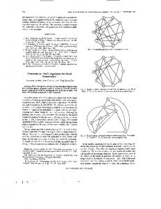
that does not satisfy condition (2), χ (τ ) = 2, for point τ on an edge (Figure 1(c)). Actually, a point τ (the point at the corner) for which χ (τ ) = 3 is introduced. Hence, connectivity constraints have to be checked before compaction.
Figure 1: Compaction with (a) Moore's neighborhood. (b) Von-Neumann's neighborhood.
Figure 2: Connectivity violation. (a) Original, (b) intended compaction, (c) false edge.
Computing separation constraints are simplified even further by assuming Von-Neumann's neighborhood in this bitmap model. Notice that, since kij=1, for all i and j, only one step for checking separation constraints is needed. Figure 1 illustrates the effect of using different neighborhoods for computing separation constraints. Hence steps 1 and 2 of the algorithm, can be executed in two time steps. The one time step is to propagate the signal and the other is to determine the critical objects in the layout, the i.e., stationary objects that are not allowed to move. The process of checking for separation constraints needs one bit per site. Two bits are required to identify edge, node, empty, and obstacle points on the graph. Therefore, a total of three bits of memory is needed per site to carry out this algorithm. This means that the space complexity of the algorithm is O(N). Notice that some configurations of moving and stationary connected objects can cause connectivity violation. Figure 2 illustrates how this can happen. In the figure, if only the separation constraints are observed, all objects in the graph are movable except for the lower three nodes and the edge connecting the east most two nodes. Suppose all movable objects are shifted one point to the east by inserting a jog between the movable part and the stationary part of the graph (see Figure 1(b)). However, if the definition for connectivity is checked, a false edge is generated
The algorithm checks such abnormal configurations in the graph layout and disables the movement of such objects (if any) by setting their status to stationary in step 2 of the algorithm. This needs at most ( N -1) time steps, since such condition must be known to all sites on a vertical line. Rules to detect such configurations are necessary [1]. The algorithm needs to check such rules in step 2. Preserving connectivity constraints dynamically is an important issue. Since all movable points will compact simultaneously (see step 2 in the algorithm), the connected object may have different moving situation. This leads to an extended number of cellular automata rules that is to be considered. Figure 3 shows a high level cellular automata algorithm for one step compaction that preserves connectivity. When every site executes the same algorithm in parallel, the result will be a one step compaction to the east.
4.2 Jog Introduction and Elimination While compacting, straight edges may bend (jog) around an obstacle if the width of the layout could thereby be reduced. Many ideas for introducing jog points have been introduced in the literature [6]. A straight forward technique is to introduce a jog wherever an edge could possibly be bent. This technique for bend introduction is adopted in the proposed compaction algorithm. The results from one dimensional compaction show a clear advantage of this method over the no jog introduction approach. Figure 4 shows an example for which about 8% more compaction can be achieved when jogs are introduced.
Efficient Cellular Automata Algorithms for Planar Graph and VLSI Layout Homotopic Compaction
Compact_East(point) begin if (status(point) = movable) then if (not(status(neighbor(point, east)) = stationary and type(neighbor(point, east)) = node)) then set_type(neighbor(point, east), type(point)); endif if (type(neighbor(point, west)) = empty) then if (((type(neighbor(point, north)) empty and status(neighbor(point, north)) = stationary) or (type(neighbor(point, south)) empty and status(neighbor(point, south)) = stationary))) then set_type(point, edge); else set_type(point, empty); endif endif if (type(neighbor(point, west)) empty and status(neighbor(point, west)) = stationary) then set_type(point, edge); endif endif end Figure 3: Parallel graph compaction
However, introducing jogs while compacting in one direction, say east, can create obstacles against compacting in the orthogonal direction, (i.e., south). To avoid this problem, compaction in the reverse direction of the original compaction without introducing jogs is done (e.g. compaction to the west after compaction to the east). Compacting without introducing jogs can cause two different subedges to align, and hence, forms a longer subedge. This process is called jog elimination, because jogs are eliminated when two subedges align together. This process maximizes the length of straight edges along the orthogonal direction of compaction. In this process of jog elimination, a subedge does not move in the direction of compaction unless all its points are movable. This is required to ensure that no jog points along the subedge are
DMFx(d) =
{
0
if d = 0
otherwise DVx(d/2) + DMFx (d/2) generated. This process can be implemented in
9
step 3 of the algorithm where the neighbors of every movable point on the layout is checked along the same subedge. If it is in the neighborhood of a stationary point, it is marked as stationary. This process propagates until all edge points are marked either movable or stationary. Fortunately, this process does not increase the time complexity of the algorithm, because there are at most ( N -1) points on a subedge that needs to do the checking. The worst case time requirement for one step compaction is O( N ). This makes the overall time for compaction to be O(N). Compared to the best known homotopic compaction results of O(N3logN) time complexity, the proposed algorithm gives an improvement of N2logN This significant improvement in time complexity makes the use CAM6 as a very attractive hardware accelerator.
Figure 4: (a) Original layout. (b) Compaction with no bends. (c) Compaction with bends.
5. Graph Compaction: Results and Analysis To test for the quality of the results, the following measures for each qualitative parameter introduced in Section 4 are defined here. For all quality measures presented below, the smaller the value of the measure, the better the compaction quality.
I. Vertex distribution measure: For the quality of distribution of vertices of a layout along the x-axis, the following new distribution measure function is proposed, which can be recursively defined as:
10
International Journal of Computing & Information Sciences
n −1 d
DVx(d) =
n×
∑ i =0
d − N x( i=+i1×)d×d −1 lx n
where n is the total number of vertices in the layout and N xj= i is the number of vertices with xcoordinates between i and j inclusively. The x value is close to zero when the layout is well distributed over the x-axis. The worst case distribution over the x-axis is when the x value is equal to log2(lx), where lx is the width of the layout along the x-axis. (The y measure function DMFy(ly) is defined similarly.) To find the x distribution measure for a layout of lx width along the x-axis, the function DMFx(lx) is computed.
BMF =
Vol.1, No. 1 ,December 2003
Number − of − bends 2 .4 n + 2
The proposed planar graph compaction algorithm has been tested on randomly generated planar graphs, hand crafted graphs and graphs described in referenced literature. The overall performance of the compaction algorithm is very promising. Figure 5 shows an example of a randomly generated graph and its compacted results, with initial layout of 250 by 250 pixel points and a total of 941 nodes. It has an average degree of 2.4 per node.
II. Edge uniform length measure: This is the standard deviation of the edge length that is defined as
∑ (l
i
EMF =
− lm ) 2
i
M −1 Figure 5: Test case for the performance analysis.
where M is the total number of edges in the graph, lm is the mean value of edge length, and li is the length of edge i in the graph.
III. Layout area measure: Since most of the embedding algorithms use a visibility representation (bipolar) that is converted into a rectilinear representation. Rosenstiehl and Tarjan's embedding bound [20], (2n2-4n)n, is used as a reference for the compaction quality. Thus, Area Measure Function is defined as AMF =
Area ( 2n 2 − 4 n ) n
IV. Number of bends measure: As a reference to these bends counted in a compacted graph, the result of Tamssia and Tollis's [22] embedding algorithm for minimizing the number of bends in a rectilinear graph is used. Since the upper bound for their embedding algorithm is (2.4n+2), the Bend Measure Function is defined as
Figure 6: Compacting to the east and then to the south using (a) jog elimination, (b) jog introduction, and (c) combination of both.
First, the test was on the effect of using different jog introduction policies for compaction. Figure 6 shows the output of compacting to the east and then to the south using three different policies. Figure 6(a) shows the output layout without introducing jogs(jog elimination), and Figure 6(b)
Efficient Cellular Automata Algorithms for Planar Graph and VLSI Layout Homotopic Compaction
shows the output with jog introduction. Figure 6(c) shows the output layout combination of the two policies; (1) compact to the east with jog introduction and then to the west with jog elimination (2) compact to the south with jog introduction and then to the north with jog elimination. Although jog elimination does not achieve as much compaction when it is done only in one direction (to the east) compared to the other two methods, on an average it gives a much better compaction in the overall two dimensional compaction processes. This is due to the fact that introducing jogs in one direction have a negative effect to the compaction in the orthogonal direction, i.e. there is a trade-off between the two orthogonal directions of compaction. Since the jog elimination policy has achieved the best compaction in most of these test cases, this policy is chosen through out the analysis of results. The measures of the graph are plotted after every compaction step. The east, south, west, and north is compacted cyclically, applying the compaction algorithm to each direction until the layout is stationary. By doing this, the plots of the four measures (vertex distribution measure, uniform distribution measure, area measure and jog measure) are obtained against the number of compaction steps. The vertex distribution measure shows a significant improvement towards the end of every compaction. In Figure 7, steps 1 to 155 indicate the range where compaction to the east occur. The x distribution measure end with 2.3 compared to 3.8 when the east compaction starts. The y distribution remains constant during compacting to the east. A similar behavior of y-distribution can be noticed when compacting to the south (steps 156 to 330). For the total distribution measure of the graph, the magnitude of the resultant vector of the x and the y distribution function vectors is computed. Plots show a local maximum in the distribution function of every compaction direction. This is because when nodes move towards a more compacted layout, some nodes reach their final destination before the others. Therefore, the nodes accumulate towards the direction of compaction.
11
The uniform edge length measure shows an overall steady improvement (see Figure 7). However, it seems that the measure function does not end with the best value, because the minimum at step 340 is not maintained through out the end of compaction. This phenomenon occurs because the area measure (the main objective function measure) is not always cooperative with the uniform edge measure. Compaction needs to expand some edges and shrink others to produce a good area reduction. However, the reduction in the area tends to produce a more uniform edge length measure, 3.5, than the one it started with, which is 5.2.
12
International Journal of Computing & Information Sciences
Vol.1, No. 1 ,December 2003
algorithm for embedding exists. To overcome these problems, the designer needs to store extra information regarding the layout to obtain the exact embedding of the graph when converting from conventional storage representation to layout. Such problems can cause an overhead in both time and space of the design automation. This investigation is on the use of compacted bitmap representation of planar graphs as a storage technique that does not require much overhead for an embedding.
Figure 7: Vertex, uniform length, area, and jog distribution measures during compaction.
Since the area measure is the main objective function during compaction, the area measure function should decrease through out the compaction process. Figure 7 illustrates that this requirement is met with around 55% reduction in the area measure. Number of jogs measure shows an improvement of 74% over the starting value (see Figure 7). This is obvious because here jog elimination policy is used. If jog introduction policy is used, then this measure will not improve as much. Instead, it will increase (i.e., get worse) dramatically. Moreover, all other measures will behave poorly due to the increased length of edges and increased number of jogs which act as an impair for improving measures during the next orthogonal compaction phase.
5.1 Storage Requirements: Conventional data structures for graphs such as linked lists, adjacency matrix, and degree sequence representation, have their own complication when used to represent large planar graph for a layout or a circuit. Among such complications it is mentioned that no unique planar embedding of the planar graph, and no easy
For comparison reasons, we will compare the proposed compacted bitmap representation of planar graphs with the most efficient typical data structure used, i.e., link list representation. In a link list representation of a graph, every node stores a list of its neighboring nodes (nodes connected to via edges) in a list. The results show a clear advantage of using compacted bitmap planar graph representation of an embedding. These experiments show that on an average it needs 2.4n bytes to represent a planar graph with total nodes of n in a compacted bitmap form. Figure 8 shows that this is the case for most planar graphs (random graphs and hand crafted graphs). It is easy to see that the link list representation of log n graphs require n* 2 *(degree+1) bytes, 8 log n where 2 is the number bytes needed to 8 address n different nodes of the graph. For a graph with an average degree of 2.5, and n less than 28, log n the value of 2 is 1. Hence, the storage area 8 would be 3.5n bytes, which is a larger size compared to the storage area of the compacted bitmap representation, 2.4n (difference of 1.1n bytes between the two methods). As the graph size grows, so does the difference. For example when n=216, the difference will increase by a factor of 2.
Efficient Cellular Automata Algorithms for Planar Graph and VLSI Layout Homotopic Compaction
13
on how to compute the separation constraints. Computing connectivity constraints is the same as in planar graph compaction. In the following, the horizontal separation constraint in east compaction is considered. The vertical case is similar.
Figure 8: Storage size for planar graph compacted bitmaps.
Using typical compression techniques of bitmaps can further enhance this remarkable observation of utilizing compacted bitmap representation of planar graphs.
6. VLSI Circuit Layout Compaction In this section, the planar graph compaction algorithm presented in Section 4 is extended to compact VLSI layouts. Although a real circuit layout consists of several arbitrary geometrical components, the simplified model of rectilinear grid and its variations are widely used [5,6]. A bitmap model is used that assumes a finite rectilinear resolution grid with λ as the grid separation unit. This model does not hide any of the essential difficulties of the real design (refer to Section 2.2 for a complete description of the bitmap model). The example in Figure 9 will be used through out this section to illustrate the VLSI layout compaction and constraints generation process.
Figure 9: Layout with design rules 2* λ and λ for nodes and wires, respectively.
Figure 10: The original layout and compacted layout with constraint layout overlaying.
The proposed algorithm assumes that the input is a feasible layout that satisfies the design rules. It is assumed that the wires are one grid unit thick, λ. If a wire is actually thicker than λ in a real VLSI layout, the design rule of the wire would be increased to incorporate the difference in thickness. Also, without loosing generality, it is assumed that all design rules use some multiple of the unit separation, i.e. in condition (1) where aij=kij*λ, for some integer constraint kij>0. A class of objects is the set of objects that uses the same design rules. For every class i, mi is defined as the maximum constrains kij for all classes j. Similar to planar graphs, the computation of VLSI layout compaction is done on a regular two dimensional cellular automata. In this case, each processing element of automata has two counters; Ce (for east counter) and Cw (for west counter), and two buffers; Be (for east buffer) and Bw (for west buffer).
6.1 Computing Critical Regions: Recall that Strict One Dimensional Homotopic Compaction has two kinds of constraints, connectivity constraints and separation constraints. In this section, the emphasis is given
In this algorithm, the main idea is to compute the critical regions. There are two types of critical objects are defined that can cause a VLSI layout to be infeasible when moved one step to the east. The first type of critical objects are objects that
14
International Journal of Computing & Information Sciences
enter critical regions if moved one step to the east. The second type of critical objects are objects that will cause other objects to enter critical regions if moved one step to the east. A procedure that can find the critical regions is described by the following four stages:
Figure 11: (a) First type of critical objects (dotted objects) and (b) Second type of critical objects (objects in the shaded area).
1. Generating Constraint regions: In this stage, a wave expansion technique is used to find a constraint region for every layout object [24]. In this wave expansion stage, wires and modules of class i assign values of their maximum constraint mi to their counters (Ce and Cw). Next, each site looks into its neighboring counters and do the following. Each site with non-zero wave counter chooses the maximum non-zero wave counter site of its neighbors, and then assigns the value of the chosen neighbor wave counter minus one to its own wave counter. Also, it copies the class buffer of the chosen neighbor to its own class buffer. Sites to the east(west) of an object carry information in their east(west) buffers. This expansion progresses until no new sites can be marked. This stage will take O(Max(mi)) time steps to execute, that is a fixed value in a design. (See Figure 10 for examples of this step.) Overlaying constraints regions are identified by two non-zero counters per cell. No more than two wave counters are needed to determine overlaying regions if a valid
Vol.1, No. 1 ,December 2003
initial layout and a one dimensional homotopic compaction are assumed. 2. Generating Critical regions: To identify critical regions, every site checks the east and the west classes and counters of every overlaying constraint region. In every overlaying region of two objects i,j ( i to the east of the overlay and j to the west), the overlay is a critical region if it satisfies the condition (mi - Cw)+(mj - Ce) ≥ kij . 3. Finding the first type of critical objects: In this stage, the first type of critical objects is specified. Since these objects are adjacent to the west of critical regions, they can be easily recognized in a single step (see dotted lines in Figure 11(a)). 4. Finding the second type of critical objects: In this stage, the second type of critical objects is considered that can cause infeasibility in the layout if moved one step to the east. To do this, every east boundary of a critical region that has an adjacent object to its east sends a wave to the west. Objects reached by the wave are considered critical and their movements are disabled (see Figure 11(b)). The process of sending waves is quite similar to the stage of generating constraint regions. However, the range of wave is decided by the design rule of object that creates it, namely, the object located to the west of the overlay. Hence the design rule of this object should be known to the overlay. Sites on the east boundary of a critical region and west of an object j, which will have the class i in their east buffer, send a wave to the west with count kij. The objects which get a wave with zero count will be identified as the second type of critical objects and are disabled from motion. This stage needs O(Max(mi)) time steps to be executed. Note that stages 3 and 4 can be done simultaneously, and the overall time complexity of the procedure of finding critical objects is O(Max(mi)) . Space wise, wave propagation with overlaying and carrying the design rule values of objects, requires each element of the cellular 2*log2(Max(mki))+2* automata to have log2(number of classes) bits. For example, a typical circuit layout having Max(mi) = 4λ with
Efficient Cellular Automata Algorithms for Planar Graph and VLSI Layout Homotopic Compaction
15
four classes of objects requires 8 bits of memory per site.
6.3 VLSI Circuit Layout Compaction Algorithm:
Notice that, in the proposed compaction algorithm, cuts are prevented from being oversaturated by disabling movements of part that can cause oversaturation. This is done by dynamically testing congestion at each point on a cut. If there is no oversaturation at each point then there will be no oversaturation in the overall cut and the overall graph. Hence, there is no need to compute congestion of the overall graph. The elimination of congestion of the overall graph is the main reason of the significant speed up of algorithm by O(N2logN).
With the procedure of how to determine critical objects in a layout presented in Section 6.1, the steps for VLSI layout compaction algorithm is similar to the planar graph compaction presented in Section 4.1.
6.2 Introducing Jogs in a VLSI Layout: As for planar graphs, in homotopic compaction of VLSI layout a previously straight wire is allowed to bend around an obstacle during the compaction, then the width of the layout could thereby be reduced.
Figure 12: Introducing a jog.
This VLSI layout compaction algorithm provides an instant solution to such problem. If a wire is partially critical, then a jog point can be introduced at the non-critical point of wire adjacent to the critical portion of the wire (see Figure 12 for an example). Jog points then need to be checked so that they obey the connectivity constraints, as done for planar graphs. Actually on cellular automata, jog points can be introduced in a constant time. The proposed algorithm is a prime candidate that can be used in homotopic compaction because it efficiently solves the critical problems of separation constraint generation and automatic jog introduction.
Since this work is on compaction in different directions (two-dimensional compaction), an obstacle of a box shape is placed around the layout to be compacted. This box size can be made as tight as possible to eliminate unnecessary shifts of the layout during compaction. During compaction, the box acts as an obstacle in all directions. Since the size of the layout reduces during compaction, it is reasonable to readjust the size of the box after every two orthogonal compactions. Step 1 of the algorithm is to determine the separation constraints of all objects in the layout. This is done through computing critical regions and critical objects. In step 2, the connectivity constraint is enforced by marking all module points on the same module either movable or stationary, but not both, and also by disabling configurations that can cause connectivity violation during the compaction of movable points. Since modules are defined as solid objects in the layout, one cannot mark some points of one module to be movable while the rest are stationary. Therefore, the module under consideration is set to be movable if all points of its boundary are marked movable. If at least one point on the module's boundary is marked stationary, then the whole module should be marked stationary. This is done by propagating this information to all points representing the module boundary, and hence, setting them all to be stationary. If module boundaries are assumed to be of length O( N ), which is a very reasonable assumption, the above process(disabling partially movable modules) should take O( N ) time steps. This should not impose any increase on the overall time complexity of the algorithm. The way to do this process as well as doing step 4 are already explained in the algorithm in planar graph compaction (Section 4.1). It was shown that at
16
International Journal of Computing & Information Sciences
most N time is needed to compute them. Therefore, the overall time complexity of the algorithm is O(N). Our VLSI layout compaction algorithm functions correctly if it maintains no oversaturated cuts throughout the layout. This is done in every compaction step when separation constraints are computed. Because of the thickness of a wire crossing, a cut and its separation constraint value are always positive non-zero values, and congestion of a cut is always maintained below its saturation value. However, a cut can either be saturated or non-saturated throughout the layout. Particularly, saturated cuts are the trigger of disabling object from moving (critical object). Therefore, explicit computation of the congestion and the capacity of a cut are not required. This is the main reason of the unprecedented performance of the proposed algorithm. The computation of the congestion and the capacity of all cuts in the layout that usually consumes as much as O(N2logN) time in the conventional compaction algorithms [6,9,25] are eliminated in this proposed algorithm.
Vol.1, No. 1 ,December 2003
7. Conclusion In this paper, efficient cellular automata algorithms for homotopic compaction of planar graph and VLSI layouts are presented that use the bitmap representation of layouts. The performance of the algorithm on planar graph layouts are analyzed in terms of four measures; the area, the number of bends, the uniformity of edge length, and vertex distribution. It is observed that to increase the performance, jogs must be introduced carefully. Sometimes it is better not to introduce them at all. The investigation also shows a clear advantage of using compacted bitmap representation of planar graph layouts over the conventional representation (e.g., linked lists) in terms of memory space.
References 1. F. Al-Anzi and S. Kim, ``Cellular Automata Algorithms for Homotopic Compaction and Expansion'', Technical Report No. 93-17, Computer Science Department, Rensselaer Polytechnic Institute, 1993. 2. D. G. Boyer, ``Symbolic Layout Compaction Benchmarks '' IEEE, pp. 186-217, 1987. 3. N. Chiba, ``Drawing Graphs Nicely'', Acta Informatica, vol. 22, pp. 187-201, 1985.
Figure 13: Computing a VLSI layout.
The positions of I/O ports in a VLSI layout design have a special importance, because it is the interface of the layout to the outside world. Therefore, it needs to preserve the I/O port positions during compaction. This makes it easy for the designer to inspect the output of the compaction process. Fortunately, the proposed compaction algorithm preserves the relative positions of I/O ports on the modules (see example in Figure 13). Notice that the circuit is minimized in size due to the consecutive compactions in different directions while I/O port positions are preserved.
4. Y.E. Cho, ``A Subjective review of Compaction'', Proceedings of 22nd Design Automation Conference, June 1985, pp. 396-404. 5. J. Fang, and J.S.L. Wong, K. Zhang, P. Tang, ``A New Fast Constraint Graph Generation Algorithm for VLSI Layout Compaction'', Proc. IEEE International Symposium on Circuits and Systems, pp. 2858-2861, Oct. 1991. 6. S. Gao, M. Kaufmann, and F. M. Maley, ``Advances in Homotopic Layout Compaction '', ACM Symposium on Parallel Algorithms and Architecture, pp. 273-282, 1989. 7. M. Y. Hsueh, ``Symbolic Layout and Compaction of Integrated Circuits'' , Ph.D.
Efficient Cellular Automata Algorithms for Planar Graph and VLSI Layout Homotopic Compaction
Thesis, EECS Division, University of California, Berkeley, CA, 1979. 8. J. JaJa, ``Parallel Algorithms for VLSI Routing '' , Integration, the VLSI Journal, vol. 12, pp.305-320, 1991. 9. M. Maley, ``A Generic Algorithm for OneDimensional Homotopic Compaction'', Algorithmica, pp. 103-128, 1991. 10. K. Mehlhorn and S. Naher, ``A Faster Compaction Algorithm with Automatic Jog Insertion '', Proceedings of the fifth MIT Conference on Advanced Research in VLSI, pp. 297-314, March 1988. 11. N.H. Packard and S. Wolfram, ``TwoDimensional Cellular Automata'', Journal of Statistical Physics, vol. 38, no. 5/6, pp. 901947, 1985. 12. A. Papakostas, I. G. Tollis, ``Efficient Orthogonal Drawings of High Degree Graphs’’, Algorithmica 26(1): 100-125 (2000) 13. A. Papakostas, I. G. Tollis, ``Algorithms for area-efficient orthogonal drawings’’, Computational Geometry 9(1-2): 83-110 (1998) 14. A. Papakostas, I. G. Tollis, ``Orthogonal Drawing of High Degree Graphs with Small Area and Few Bends”, WADS 1997: 354367 15. A. Papakostas, I. G. Tollis, ``Improved Algorithms and Bounds for Orthogonal Drawings”, Graph Drawing 1994: 40-51 16. P. Rosenstick, and R. Tarjan, ``Rectilinear Planar Layout and Bipolar Orientation of Planar Graphs'', Discrete Computer Geometry, vol. 1, pp. 343-353, 1986. 17. S. Sastry and A. Parker, ``The Complexity of Two-Dimensional Compaction of VLSI Layout'', Proceedings of ICCC-82, Sept. 1982, pp. 402-406.
17
18. R. Tamassia, and I. Tollis, ``Planar Grid Embedding in Linear Time'', IEEE Transactions on Circuits and Systems, vol. 36, no. 9, pp. 1230-1234, Sept 1989. 19. T. Toffoli, ``CAM: A High-Performance Cellular-Automaton Machine'', Physica 10D, pp. 195-204, 1984. 20. A. Torralbo, ``A systolic array with applications to Image Processing and Wirerouting in VLSI Circuits'', Parallel Computing, vol 17, pp. 85-93, 1991. 21. X. Xiong, ``Geometric Approach to VLSI Layout Compaction'', International Journal of Circuit theory and Applications, vol.8 (1990), pp. 411-430. Fawaz S. Al-Anzi is an Associate Professor in Computer Engineering Department at Kuwait University. He holds a BS degree with honours in electrical engineering from Kuwait University, and MS and PhD degrees in Computer Science from Rensselaer Polytechnic Institute, New York, USA. His current research interests are in Internet scheduling, Arabic language processing, engineering databases, knowledge management and data mining. He has published in International Journal of Computer and Application, International Journal of Parallel and Distributed Systems and Networks, Journal of Computers & Operations Research, Complexity International Journal, and Journal of Computers and Humanities.