for the ARM processor without taking into account the large external ROM size overhead. In [7, 8], the authors devel- oped a dictionary-based algorithm that ...
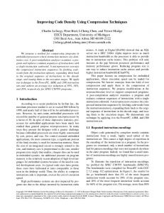
Efficient Code Density Through Look-up Table Compression Talal Bonny and Joerg Henkel University of Karlsruhe Department of Computer Science Karlsruhe, Germany {bonny,henkel}@informatik.uni-karlsruhe.de
Abstract Code density is a major requirement in embedded system design since it not only reduces the need for the scarce resource memory but also implicitly improves further important design parameters like power consumption and performance. Within this paper we introduce a novel and efficient hardware-supported approach that belongs to the group of statistical compression schemes as it is based on Canonical Huffman Coding. In particular, our scheme is the first to also compress the necessary Look-up Tables that can become significant in size if the application is large and/or high compression is desired. Our scheme optimizes the number of generated Look-up Tables to improve the compression ratio. In average, we achieve compression ratios as low as 49% (already including the overhead of the Lookup Tables). Thereby, our scheme is entirely orthogonal to approaches that take particularities of a certain instruction set architecture into account. We have conducted evaluations using a representative set of applications and have applied it to three major embedded processor architectures, namely ARM, MIPS and PowerPC.
1. Introduction and Related Work The increasing demands on the application of embedded systems caused them to grow rapidly. For instance, more than 60MB of software is installed in the current premium cars [4]. Since the cost of an integrated circuit is closely related to the die size, and the memory chip dominates a large part of the chip area, a reduction of the cost can be achieved by reducing the memory size. This can be done by using code compression which can also reduce the power consumption since memory consumes a significant amount of an embedded system’s power consumption [2, 10, 11]. The beginning of this trend has already been recognized in the early 1990s, when first approaches to code compression of embedded applications arose [16]. Proposed compression
978-3-9810801-2-4/DATE07 © 2007 EDAA
schemes may be classified into two general groups: statistical and dictionary schemes [1]. In statistical compression schemes, the frequency of instruction sequences is used to choose the size of the code words that replace the original ones. Thereby, shorter code words are used for the most frequent sequences of instructions, whereas longer code words are replaced by less frequent sequences. In dictionary compression methods, entire sequences of common instructions are selected and replaced by a single new code word which is then used as an index to the dictionary that contains the original sequence of instructions. In both cases, Look-up Tables are used to store the original instructions. The compressed instructions serve as indices to the tables. One of the major problems is that the tables can become large in size, thus diminishing the advantages that could be obtained by compressing the code. However, the entire research in the area has always focused on achieving better code compression without explicitly targeting the problem of large Look-up Table sizes. In our work we reduce the size of the Look-up Tables generated from dictionary and statistical compression methods by sorting the table’s entries to decrease the number of bit toggles between every two sequential instructions, then we optimize the number of generated Look-up Tables to achieve a better compression ratio. Interestingly, our method is orthogonal to any kind of approach that uses a priori knowledge of the instruction set of a specific architecture. Hence, all results we report might be further improved by ISA-specific compression approaches. Previous work can be categorized by dictionary- and statistical-based schemes. There are several related approaches that use dictionary-based schemes. In [17], the authors developed a compression algorithm to unify the duplicated instructions of the embedded program and assign a compressed object code. Their technique typically needs a large external ROM. A 37.5% compression ratio is achieved for the ARM processor without taking into account the large external ROM size overhead. In [7, 8], the authors developed a dictionary-based algorithm that utilizes unused en-
coding space in the ISA for RISC processor to encode code words and addresses issues arising from variable-length instructions. A compression ratio not better than 65% is achieved. In [6], the authors extracted common sequences and placed them in a dictionary. Average compression ratios of 61%, 66% and 74% were reported for the PowerPC, ARM and i386 processors, respectively. Statistical methods are used in [12], The authors proposed LZW-based algorithms to compress branch blocks using a coding table. The maximum compression ratio achieved is 75% for a VLIW processor. In [16], the authors have designed a new RISC architecture called CCRP (Code Compressed RISC Processor) which has an instruction cache that is modified to run with compressed programs. Compression ratios are rated from 65% to 75%. In [15], compiler-driven Huffman-based compression with a compressed instruction cache has been proposed for a VLIW architecture. An Address Translation Table (ATT) is generated by the compiler, containing the original and compressed addresses of each basic block and its size. Common to all work in code compression is that Look-up Tables are deployed for decoding. They can come as LAT or ATT. In any case, these tables will take space in memory and significantly impact the total compression ratio. Hence, an efficient compression ratio can be accomplished by minimizing both the code itself and the table(s). This is crucial since an average table size can reach more than 30% compared to the original code size as we have found through a large set of applications (see Fig. 4 and UR bar in Fig. 5). Our novel contributions are as follows: (1) As the first hardware-based approach we explicitly reduce the size of the Look-up Table using a table compression scheme. Hence, we are the first to combine a code compression scheme (we use Canonical Huffman coding) with a table compression scheme. (2) We optimize the number of the Look-up Tables generated from Canonical Huffman coding to achieve a better compression ratio. (3) The compression scheme of the Look-up Table is entirely orthogonal to any instruction set architecture. That means, the achieved total compression ratio could be further improved if ISA-specific knowledge were used on top of our approach. The rest of the paper is organized as follows. In Section 2 and 3, we present our table compression technique for the dictionary-based method and the statistical method respectively. In Section 4, we introduce our hardware implementation for both schemes. Experimental results are presented in Section 5. We conclude this paper with section 6.
2. Dictionary-Based Compression Scheme In order to demonstrate the usefulness of our Look-up Table minimization scheme, we deploy it in conjunction with Yoshida’s technique [17] that uses a dictionary-based method to generate the Look-up Table.
Figure 1. Example for compressing LUT.
2.1. Generating compressed code and LUT To generate the Look-up Table and the compressed code we conduct the following steps: (1) Starting from the original (i.e. un-compressed) binary code, we unify the entire instruction words. (2) We store all unique instruction words in one Look-up Table. (3) In the original code we replace every unique instruction word with a binary index to the Look-up Table in ascending order starting from 0. Here, the index has a fixed length equal to log2 of the number of the unique instructions. To solve the problem of locating the branch addresses in memory, we patch these addresses to the compressed ones as adopted in [6]. We can compute the compression ratio in this scheme as follows: P N × log2 (n) + W i=1 Ci (1) CR = W ×N W: Instruction word length (table width) N: Number of original instructions n: Number of unique instructions (number of table entries) Ci : Size of table column i (in bit) Obviously, in order to improve the compression ratio by decreasing the table size, either the instruction word length W or the size of table column C needs to be decreased. Note that W is fixed. That leaves Ci , a measure of the LUT size, as an option. Decreasing the size of the table columns Ci is explained in the next section.
2.2. Minimizing the Look-up Table cost Minimizing the Look-up Table cost can be achieved by reducing the size (in bits) of the table columns as shown in CR formula in Section 2.1. The principle of compressing the table is to minimize the number of bit transitions per column (for example from top to bottom) and then saving the indices only where a bit toggle occurs instead of saving the complete column. See the top part of Fig. 1. This
figure illustrates a demonstration for compressing a Lookup Table with a number of entries n=7 and instruction word length W=8. The size (cost) of the original table is 56 bits. By compressing it, its size becomes 47 bits. To compress the columns of the LUT, we use the same algorithm used in [3]. Achieving higher table compression by compressing more table columns basically depends on the way of sorting its entries. Therefore, we sort the entries in two phases. In the first phase, we generate Gray code for W bits (i.e. the table width), then we locate each table entry in its corresponding position in the generated Gray code. In the second phase, we use the Lin-Kernighan heuristic algorithm [9] which sorts the table entries in a way that the sum of the distances between each two successive entries is minimal (or close to it). In our case, the distance between two entries is the number of positions for which the corresponding bits are different. Sorting the entries of the Look-up Table will have no impact on the size of the compressed instructions, because all of them have the same code length (log2 n). It will just decrease the size of the Look-up Table and consequently improve the compression ratio (Eq. 1 ). Returning to Fig. 1, and after sorting the table’s entries, the size of the table will be decreased to 35 bits.
3. Statistical Code Compression Scheme In this scheme we use the Canonical Huffman Coding to generate the compressed code and the Look-up Tables. The number of the generated Look-up Tables is equal to the number of different instruction code lengths. We use our table compression scheme to minimize the table cost.
3.1. Generating compressed code and LUTs Huffman Coding [1] is a well known method based on probabilistic distribution. Most frequent occurring instructions are encoded with the shortest codes and vice versa. Huffman Coding produces the best possible compression ratio for a given input stream of symbols. The problem in Huffman Coding, however, is the decoding because of the variable length codes. This is a major problem when it comes to hardware implementation. To overcome this problem we use the Canonical Huffman Coding, which is a subclass of the Huffman Coding that has a numerical sequence property, i.e. code words with the same length are binary representations of consecutive integers [14]. We first encode the instructions using Huffman Coding to find out the code length for every instruction and the frequency for every length. Then we compute the first code word for each code length as follows: The first code word for any code length is equal to the first code word for the one bit longer code length plus its code length frequency. Finally, we create the remaining code words for each length using the numerical sequence property. We can compute the
Algorithm 1 TCM: Table Cost Minimization N1, N2: # of all instructions in T1 and T2 ch[min,max]: # of transferred instruction from T1 to T2 F: Instruction’s frequency, L: # of tables 1. default efficiency= 0, k= ch.min= 1, ch.max= N1 2. repeat= 10 // # of repetition steps /* compute the tables cost before the transferring */ 3. cost1= table cost(N1) 4. cost2= table cost(N2) 5. cost before= cost1 + cost2 6. while (k < ch.max) do 7. for (each step s of repeat) do 8. for (each instruction i of k) do 9. transfer random instruction from T1 to T2 10. Loss= Loss + F(i) // compute the loss end for 11. /* compute the tables cost after the transferring */ 12. cost1= table cost(N1 - k) 13. cost2= table cost(N2 + k) 14. cost after= cost1 + cost2 15. efficiency= cost before + cost after - Loss 16. delta= efficiency - default efficiency /* Check if the transferring is good */ 17. if (delta > 0) then 18. default efficiency= efficiency else 19. 20. return the transferred instruction to T1 end if 21. 22. end for 23. k++ 24. end while 25. return(T1,T2)
compression ratio in this scheme as: CR =
PL
i=1
Ni × CLi +
PL PW i=1
j=1
Cji
W×N
(2)
L: Number of different code lengths (number of LUT) Ni : Number of instructions which have the code length i CLi : The code length i Cji : The size of column j in table i If L=1 (there is only one Look-up Table), then we will obtain the same compression ratio formula (Eq. 1)
3.2. Minimizing the Look-up Tables cost Now, we can use the same scheme for minimizing the cost of each generated Look-up Table (i.e. its size) that we have used in section 2.2. To minimize the Look-up Tables size, we use two methods: (1) Minimizing each Look-up Table size separately. In this case, the instructions that belong to any LUT will be sorted
Figure 2. Optimizing the number of LUTs withinPthis P table. This will minimize the cost of the LUT L W (i.e. i=1 j=1 Cji ) and will have no impact on the comPL pressed instruction size (i.e. i=1 Ni × CLi ) because the number of instructions which have the code length i (i.e. Ni ) will not be changed after the sorting. (2) Minimizing the cost of all Look-up Tables together. That means, the instructions that belong to any LUT can be transferred to a new LUT if that will improve the final compression ratio. Note that this process will decrease the number of LUTs by deleting the instructions from some of them and inserting them in another LUTs. This will give a better chance to compress more columns in each table and consequently minimize the total compressed tables cost. On the other hand, this process is counterproductive for the code size as the compressed code is generated using the (non-resorted) LUT. If some instructions are transferred from one LUT to another one, the efficiency is computed as follows: Eff. = Compressed Table Gain - Compressed Code Loss such that, the compressed table gain is the difference between the size of the compressed tables before and after transferring instructions between them. The compressed code loss is the difference between the size of the compressed codes before and after transferring instructions. Algorithm 1 shows how to minimize the Look-up Tables cost by transferring instructions between LUTs. The Algorithm computes the table cost before and after transferring K random instructions from one table T1 to another one T2 and then it computes the efficiency (line 16). If it is better than the efficiency in the previous step, it keeps the new tables, otherwise it returns the transferred instructions in this step back to Table T1. Fig. 2 illustrates the effects of decreasing the number of the LUTs on the compressed instruction size, the compressed Look-up Tables size and the total compressed code size for the Math benchmark (compiled for ARM) to optimize the Look-up Table cost. Decreasing the number of Look-up Tables to be ’1’ can achieve the best table compression because this will give a better chance to compress more columns in each table through re-occurring patterns. On the other hand, this will increase the instruction cost to its maximum value because all the instructions (the most frequent and the less frequent sequences) will have the
Figure 3. Canonical Huffman Decoder. longest code word. Consequently, the code cost will be increased, too. The optimum solution in this example is 8 LUTs. This will increase the tables cost slightly but will reduce the instructions cost significantly and consequently the total code cost will be reduced.
4. Hardware for de-compression The decompression hardware consists mainly of two parts: Canonical Huffman decoder and Look-up-Table(s) decoder. The dictionary-based compression scheme uses the Look-up Table decoder part. The statistical compression scheme uses both decoder parts.
4.1. Look-up Table decoder In the Look-up Table decoder, the compressed columns are stored in FPGA Block RAMs, one column in each Block RAM, while the un-compressed columns are stored in external ROM. When the decoder receives the compressed instruction, it finds out its position in each Block RAM. If it is in an even position, the decoder generates ’0’ in that position, otherwise it generates ’1’. We implemented the decoder in VHDL and synthesized it with Xilinx ISE8.1 for VirtexII. An access time of 3 ns was achieved and the number of slices needed for the decoder was 430.
4.2. Canonical Huffman Decoder We designed a new Huffman decoder which decodes the Canonical Huffman encoded instructions on the fly (without delay). The decoder architecture is illustrated in Fig. 3. The decoder contains two shift registers: 32-bit and L-bit shift registers (L is the longest Canonical code word length). The main task for the 32-bit shift register is to receive the compressed instructions and to keep the L-bit shift register filled each time its content is reduced by shifting the compressed instruction word serially into it. The L-bit shift
Figure 4. Original and unique instructions
Figure 5. Table Compression Ratios register transfers the L bit code words to the comparators. The task of these comparators is to decode the length of the encoded instructions from the incoming L bits. Each comparator compares the incoming L bits with the minimum index of the corresponding table. If the incoming L bits are bigger or equal to the minimum index of that table, the corresponding comparator outputs a ’1’, otherwise ’0’. The table selector finds out the smallest comparator which outputs ’1’. This comparator number refers to the code word length and finally to the corresponding compressed Look-up Table. The compressed Look-up Tables are decoded using the Look-up Table decoder explained in the previous section. The decoder has been implemented in VHDL and synthesized with Xilinx ISE8.1 for VirtexII. The access time of 3.5 ns was achieved and 600 slices were used.
5. Experiments and Results In this section we present the performance results of both compression schemes: dictionary-based and statisticalbased compression schemes. In order to show the efficiency of our schemes, we have conducted results for three major embedded processor architectures, ARM(SA110), MIPS(4KC) and PowerPC(MPC85). It is also a goal to demonstrate the orthogonality as far as specific ISAs are concerned. For all architectures and all schemes the MiBench [13] benchmark suite has served as a representative set of applications. We have compiled the benchmarks using three cross-platform compilers, each for one target architecture. The final results are presented in Figures 4-8.
They do account for the overhead stemming from the LUTs. In each diagram, the bar labeled ”Average” shows the average across all benchmarks. Fig. 4 presents the number of original and unique instructions for different benchmarks and across the three architectures. This figure shows that the number of instructions generated by compiling a benchmark for the ARM architecture is always less than compiling the same application for MIPS or the PowerPC since the ARM is the most dense among the other RISC processors. This will result in the fact that the number of unique instructions will also be lowest for the ARM. The ratio of the number of unique instructions to the number of original ones, denoted as UR, is presented in Fig. 5. This ratio gives an idea of how important table compression actually can be: in fact, we have found that the amount of unique instructions can account for between 30%, 32% and 37% of all instructions for ARM, MIPS and PowerPC, respectively. Hence, the LUT has a significant effect on the final compression ratio. From the experimental results we can observe the following: (1) Table Compression Ratio TCR, in Fig. 5, is better for the applications with more unique instructions. In Fig. 4, the number of unique instructions in average is more for MIPS among the other architectures and hence, the TCR, in Fig. 5, is the best for MIPS. (2) The TCR in the dictionary based scheme is better than in the statistical based scheme because the LUTs in the second scheme are separated into a few smaller LUTs, each of which needs to be compressed separately. Minimizing the tables cost in the second scheme improves the TCR but it is still better in the first scheme. Figures 6, 7 and 8 show the compression results for both schemes and for the architectures ARM, MIPS and PowerPC, respectively. In each chart the first bar stands for the original code size. The second and the third bars stand for the compressed code size for the first and the second schemes respectively. The compressed code size includes the size of compressed table(s) + the size of compressed instructions. The second scheme achieves a better compression ratio CR than the first one although the TCR is better for the first scheme, because of using the Canonical Huffman Coding properties that go along well with our LUT compression. The average compression ratios achieved using the first compression scheme are 58%, 60% and 62%, and using the second scheme are 52%, 49% and 55% for ARM, MIPS and PowerPC, respectively. Note that no ISA-specific knowledge has been used to obtain these ratios. The best compression ratio in our second compression scheme was obtained for the MIPS architecture because it has more number of unique instructions. Fig. 9 shows the time needed to execute the original and the compressed programs (in cycles) using the SimpleScaler [5] performance simulator. The performance overhead obtained is due to the LUT delay every time a branch instruction occurs.
Figure 6. Compression results for ARM
Figure 8. Compression results for PowerPC
Figure 7. Compression results for MIPS
Figure 9. Time taken in cycles
6. Conclusion We have presented a novel approach as a key to efficient code density namely using LUT compression in conjunction with statistical- and dictionary-based compression schemes. Our schemes are orthogonal to any ISAspecific characteristic. Without ISA-specific knowledge we achieved an average compression ratios 52%, 49% and 55% for ARM, MIPS and PowerPC including the LUT overhead.
References [1] T. Bell, J. Cleary, and I. Witten. Text compression. PrenticeHall, Englewood Cliffs, 1990. [2] L. Benini, A. Macii, and A. Nannarelli. Cached-code compression for energy minimization in embedded processors. ISLPED-01, pp. 322-327, 2001. [3] T. Bonny and J. Henkel. Using Lin-Kernighan Algorithm for Look-up Table compression to improve code density. GLSVLSI’06, pp. 259-265, 2006. [4] M. Broy. Automotive software and systems engineering. MEMOCODE, pp. 143-149, 2005. [5] D. Burger and T. Austin. The simplescaler tool set, version 2.0. Technical Report CS-TR-97-1342, University of Wisconsin-Madison, 1997. [6] C. Lefurgy, et al. Improving code density using compression techniques. MICRO- 30, pp. 194-203, 1997. [7] D. Das, R. Kumar, and P. Chakrabarti. Code compression using unused encoding space for variable length instruction encodings. VLSI Design & Test Workshop (VDAT), 2004.
[8] D. Das, R. Kumar, and P. Chakrabarti. Dictionary based code compression for variable length instruction encodings. The 18th Int. Conf. VLSI Design, pp. 545-550, 2005. [9] K. Helsgaun. An effective implementation of the LinKernighan traveling salesman heuristic. European Journal of Operational Research, 2000. [10] H. Lekatsas, J. Henkel, V. Jakkula, and S. Chakradhar. A unified architecture for adaptive compression of data and code on embedded systems. Proc. of 18th. the Inter. Conf. on VLSI Design, pp. 117-123, 2005. [11] H. Lekatsas and W. Wolf. SAMC: A code compression algorithm for embedded processors. Trans. on CAD, 99. [12] C. Lin, Y. Xie, and W. Wolf. Lzw-based code compression for VLIW embedded systems. Proc. of the Design, Automation and Test in Europe conference, pp. 76-81, 2004. [13] M. Guthaus, et al. A free, commercially representative embedded benchmark suite. IEEE 4th Annual Workshop on Workload Characterization, 2002. [14] Y. Nekritch. Decoding of Canonical Huffman codes with Look-up Tables. Proceedings of the Conference on Data Compression, pp. 566, 2005. [15] Y. Sergei, Larin, and M. Conte. Compiler-driven cached code compression schemes for embedded ILP processors. MICRO-32., pp. 82-92, 1999. [16] A. Wolfe and C. Chanin. Executing compressed programs on an embedded RISC processor. in Proc. 25th Annual Int. Symp. Microarchitecture, pp. 81-91, 1992. [17] Y. Yoshida, B.-Y. Song, H. Okuhata, T. Onoye, and I. Shirakawa. An object code compression approach to embedded processors. SLPED-97, pp. 265-268, 1997.