Apr 17, 2007 - promising opportunities for ocean exploration in search of energy resources .... nodes, and error recovery methods like retransmission.
WB1.1
Efficient Data Delivery with Packet Cloning for Underwater Sensor Networks Peng SUN1, Winston K.G. SEAH1, 2, and Pius W.Q. LEE2 1
Network Technology Department, Institute for Infocomm Research 21 Heng Mui Keng Terrace, Singapore 119613 2
School of Computing, National University of Singapore 3 Science Drive 2, Singapore 117543 In a sensor network, there are likely to be multiple paths from a sensor to the sink and these paths may or may not be disjoint. It has been shown that routing over multiple disjoint paths increase the packet delivery ratio and achieves timeliness of delivery. However, it comes at a cost of higher energy usage and possibly adding more traffic (packet duplicates) to the network when the link quality is good. Depending on how the paths are selected, there is a strong likelihood of contention occurring among nodes that are on different paths but close to one another. As these paths converge at the sink, the possibility of contention is even higher. Hence, the benefits of multipath routing are diminished when paths are not disjoint and can be totally nullified by the contention among nodes. The contention that arises among nodes in close proximity need not be viewed negatively. We can benefit from the nodes’ proximity and ability to overhear transmissions for the purpose of enhancing packet delivery. In this paper, we present a data delivery scheme that exploits this feature to selectively clone packets to forward to the sink. Unlike controlled broadcast or conventional multipath routing where duplicated packets are indistinguishable and nodes have no means of determining how many duplicates have been introduced into the network, our scheme is able to control the number of packet clones according to the channel conditions and link quality so as to improve the probability of successful delivery while minimizing contention and energy expenditure. In Section 2, we discuss the challenges faced by UWSNs, and then introduce performance metrics with usage examples in Section 3. In Section 4, we present the design of our data delivery scheme. We validate our scheme with simulations and show, in Section 5, that it fulfills the goal of achieving fast and reliable data delivery in the harsh conditions presented by the acoustic channel. Before we conclude, we discuss related work and some implementation issues.
Abstract – Underwater sensor networks (UWSNs) promises new opportunities for exploration of the oceans which cover more than 70% of the earth’s surface. Researchers envision the deployment of dense networks of untethered sensors underwater for data acquisition to better understand the underwater environment, while military and security forces see the great potential of using this technology for mine reconnaissance, intrusion detection and surveillance. However, the underwater environment is extremely harsh and acoustic communications is currently the only physical layer technique considered viable. This presents a wireless channel that is totally different from the radio frequency channel that terrestrial wireless sensor networks technology has been designed for. Key challenges include the long propagation delay of the acoustic signal and the extremely volatile link quality. In this paper, we present a data delivery scheme that exploits nodes’ proximity and their ability to overhear one another’s transmissions to enhance packet delivery by selectively cloning packets as they are forwarded. Unlike directed or controlled flooding, our scheme is able to control the number of packet clones according to channel conditions and link quality to improve delivery while minimizing contention and energy expenditure. Keywords – underwater networks, wireless sensor networks, data delivery, acoustic communications.
I.
INTRODUCTION
While underwater sensor networks present many promising opportunities for ocean exploration in search of energy resources, environmental monitoring and early warning of natural disasters, like tsunamis, there are key technical challenges to be overcome. The current viable transmission technique adopted by underwater sensor networks is acoustic communications, and the signal propagation delay of acoustic channels is five orders of magnitude slower than radio frequency (RF) channels. A high propagation delay makes it time-consuming to detect packet loss, which has a major impact on the protocols that have been designed for conventional RF-based terrestrial wireless sensor networks. Moreover, the acoustic channel is prone to regional and unpredictable disruptions, resulting in temporal disconnections which can lead to frequent link status updates and excessive re-routing for conventional routing protocols. Such frequent updates drain energy resources, and defeat the efforts of link measurement as the time cost of link measurement is significantly higher due to the long propagation delay.
1-4244-1208-0/07/$25.00 ©2007 IEEE.
II. CHALLENGES A typical application of UWSNs may be in an offshore deepwater oil drilling scenario, as shown in Figure 1. Sensors are deployed on the seabed, and data acquired by sensors are sent to smart anchors (collection points) by relaying across sensors using multi-hop communications. These smart anchors serve as local sinks for the sensor data and they are connected by cables to data acquisition system surface platforms where the data are processed and/or forwarded to remote systems for analysis and processing.
34
UT07+SSC07, Tokyo, Japan, 17-20 April 2007.
wireless acoustic links wireless sensors smart anchor
incur excessive latency and signaling overheads. Multihop scenarios will substantially amplify the effect. When data packets need to be delivered as fast as possible, such mechanisms become a big drawback. It would then appear that forward error correction (FEC) techniques can be applied to provide robustness against errors but at the cost of additional redundant bits competing for the already scarce bandwidth, and the processing needed for encoding and decoding further drains the critical energy resources.
Floating rig
D. Energy and Cost Constraints While terrestrial sensor networks are designed with a dense deployment in mind as they are expected to become very inexpensive, it is not so for underwater sensor networks. The harsh physical underwater environment requires special casing to contain the electronics and often the cost of the casing makes up a larger portion of the total cost of an underwater sensor platform. Deploying an UWSN is also a difficult and costly operation. UWSN nodes are therefore fewer and distances between nodes longer. Coupled with the poor channel conditions, this translates to higher energy usage for longer range transmission and the use of more complex signal processing schemes for reliability. Once deployed, it is often difficult if not impossible to replace the energy source (batteries) after they have been expended. Furthermore, alternative energy sources, like solar energy, are not available in the dark depths of the ocean. The energy constraints make a multihop approach attractive as the energy cost for wireless communication is exponential to the distance between sender and receiver [3]. Given an arbitrary distance, relaying packets using a multihop approach can save significant energy compared to a single long range transmission. However, it comes with other costs which must be considered too.
Figure 1. UWSN in deepwater oil drilling Once the sensor data reach the sinks, the UWSN has accomplished its task. Similar network architectures can be applied to other applications such as tsunami early warning systems, environmental monitoring of the oceans, perimeter security of naval and other key installations, etc. Acoustic communications is used underwater instead of RF as RF signals suffer from high attenuation from energy absorption (except at extremely low frequencies.) This presents new challenges to protocol design, which we shall discuss in the following subsections. A. Long latency and limited bandwidth The underwater acoustic channel is characterized by long latency and low bandwidth. The propagation speed of acoustic waves at 1.5×10³ m/s is five orders of magnitude slower than RF propagation speeds. Long range transmission over tens of kilometres can attain bandwidths of only a few kHz while short range communications in the order of tens of metres may have a bandwidth of a few hundred kHz. In either case, the resultant bit rate is very low, in the order of tens of kbps, at best [1]. Studies conducted on both research as well as commercial modems have shown highly variable link capacities with range*rate product of less than 40km-kbps [2].
E. Volatile Link Quality The underwater link quality is extremely volatile, and suffers frequent temporal disconnections due to numerous reasons, such as noise (both man-made and ambient) temperature fluctuations, and severe multipath fading. A Current approaches use some form of transmission to measure the link quality which is time consuming with regard to the huge propagation delay; thus, link quality measurement incurs a considerably high cost or overhead for the underwater scenario. Moreover, a link that has been determined to be of good quality may experience poor link conditions moments later, rendering the costly process useless. The volatile link quality leads to quickly outdated neighborhood status and connectivity information, which is the cornerstone of most routing protocols. Hence, to maintain valid and useful neighborhood status information in the presence of volatile links can be prohibitively costly.
B. Noise, High Bit Error Rates and Transmission Loss The underwater acoustic channel is subjected to various sources of noise. Man-made noise can come from shipping activity and machinery while ambient noise has its origins in hydrodynamics, like wave motion, storms on the surface, etc., and biological sources like seismic activity, fishes swimming, and snapping shrimps. Noise levels can be so high as to cause link blackouts, while intermittent noise results in transmission errors and data loss. Without noise, there is still transmission loss from signal attenuation and geometric spreading; both effects increase with distance with attenuation also increasing with frequency. C. Reliability The radio propagation speed of 3.0×10⁸ m/s is negligible compared to the acoustic channel propagation delay. While automatic repeat request (ARQ) techniques are commonly used in terrestrial wireless communications for packet loss detection, the long propagation delay of the acoustic channel coupled with the low bit rate results in the large bandwidth-delay product problem. Single-hop loss detection will incur at least a round trip delay between two nodes, and error recovery methods like retransmission
III. PERFORMANCE METRICS To quantitatively study the problem, we define metrics for robustness, timeliness, and energy efficiency. The metrics aim to measure the quality of data dissemination in an UWSN. The metrics are defined using a general sensor field with n sensors, namely s1, s2, s3, s4, s5, …, sn and one sink s0. We then illustrate these metrics with two simple examples and discuss the design tradeoffs.
35
underwater link quality, our fist step is to model each link with a packet loss ratio p, 0≤p≤1. p can be affected by many factors, such as, the medium access control (MAC) scheme, hardware performance, environmental factors, effectiveness of the error correction and coding scheme, etc. Figure 2 shows three nodes connected by two links, each link associated with a p value, p1 and p2 respectively.
A. Robustness We measure robustness using the packet delivery ratio R, and this ratio can be used to describe both individual sensors and the entire sensor field. A single sensor, say sensor si, its packet delivery ratio is denoted as R(si), and defined as : R( s i ) =
m × 100% k
(1)
p1
where k is the total number of distinct packets sent by si (to sink), and m is the distinct packets arrived at the sink. It is important to emphasize distinctiveness, because one packet may have different copies arriving at sink. The sensor field overall packet delivery ratio (denoted as Rfield) is the average of every sensor nodes: R field =
1 n ∑ R( s n ) n i =1
Bit Error Rate Hardware Env factors Error correction Coding scheme
(2)
B. Timeliness Timeliness is measured as the time normalized against the average time for a single-hop along the shortest path from a sensor to the sink. It is only applicable to those packets that are successfully delivered from source to sink. The average delay, from a packet leaving a source (say si) to the first copy of that packet arriving at the sink, is denoted as T(si). The average delay of all n sensors, denoted as Tall, is given by: Tall =
1 n ∑ T (si ) n i =1
Tall 1 ∑ h( s i ) n i =1 n
=
i =1 n
i
∑ h( s ) i =1
=
(3)
1 n T (si ) ∑ n i =1 h( s i )
(p)
E. Per-hop Acknowledgement Protocol We now use a simple topology, as shown in Figure 3, to illustrate the metrics defined above. There are three sensors, i.e., s1, s2, s3, and one sink, s0, and each link has 50% packet loss. The minimum hop count for each sensor is 3, 2, and 1, for s1, s2, and s3, respectively. For simplicity, we assume each hop has a 1-unit time delay.
s2
s1
s3
s0
Figure 3. Simple linear topology using per-hop ACK The data delivery protocol delivers a packet generated a sensor in the following manner. For each hop, the sender will wait for an acknowledgment (ACK), and the timeout value is 2 time units. If the ACK is not received, the sender will retransmit the packet again. Since the packet will be keep sending until an acknowledgment is received, thus giving a packet delivery ratio of 100%, i.e. R(s1) = R(s2) = R(s3) = Rfield = 100%. For a packet to be successfully delivered from s3 to s0, on the average, s3 has to transmit the packet twice (due to the 50% packet loss). Thus, the average delay T(s3) is 2 units of time. Similarly, T(s2)=4 and T(s1)=6, assuming the packet is being relayed immediately to next hop – an ideal scenario in which an ACK can be sent simultaneously with the data forwarding. In practices, there are hidden and expose terminal problems, which result in the total time delay to be longer than that of the ideal case. Accordingly, Tall and Tfield are:
n
T field =
packet loss ratio
Figure 2. Abstract model of link quality
Obviously, the delay does not only depend on the routing mechanisms, but also on the scale of the network. More hops will inevitably produce a larger delay value and in order to eliminate the effect of the scale of network, we measure the timeliness as follows:
∑ T (s )
p2
(4)
i
where h(si) is the minimum hop count from si to sink. Tfield is basically the average delivery delay over the average hop count. It shows how fast a packet is being delivered from source to sink. The best value of Tfield is 1, which means every packet is delivered using the minimum hop count and each hop is performed successfully. C. Energy Efficiency Energy cost is measured based on the number of packet transmissions since transmission cost is dominant [4]. Denote by E(si) the average number of transmissions incurred for delivering one packet from source, si, to sink, we define the energy efficiency of the sensor field as:
Tall =
1 3 1 ∑ T ( s i ) = 3 ( 6 + 4 + 2) = 4 3 i =1
n
E field =
∑ E(s ) i =1 n
i
(5)
T field =
1 ∑ h( s i ) n i =1
Tall 4 = =2 1 1 3 (3 + 2 + 1) h( s i ) ∑ 3 3 i =1
The first copy of a packet arriving at sink s0 does not stop the other nodes from sending packets. Each node will keep sending until an ACK has been received. For example,
D. Link Modeling Considering the high bit error rate and volatile
36
s3 will keep sending to s0 until the acknowledgment from s0 is received by s3. Since each acknowledgment has a 50% chance of being lost, s0 will send two ACKs per packet on the average. In turn, each ACK requires s3 to transmit twice. On average, s3 has to send four packets to generate the two ACKs from s0, giving an energy cost of six packet transmissions, i.e. E(s3)=6. Similarly, E(s2)=12, E(s1)=18, and Efield is given by: E field =
striving to optimize one of the three metrics. The Per-hop ACK protocol incurs high energy costs to achieve robustness, whereas Best-Effort Delivery foregoes robustness to save energy costs. The Best-Effort protocol is able to achieve the ideal timeliness criteria for the 30% of packets delivered while Per-Hop ACK lags slightly in terms of timeliness but was able to deliver all the packets. While the difference in timeliness is insignificant, there is a clear tradeoff between robustness and energy costs.
18 + 12 + 6 = 18 1 (3 + 2 + 1) 3
IV. DATA DELIVERY SCHEME Unlike terrestrial wireless sensor networks, nodes in an UWSN are unlikely to be randomly deployed. UWSN nodes need to be anchored to the ocean floor or through some other means to prevent them from being quickly swept away by the currents. Nodes that are fixed to the ocean bottom are unlikely to move much (if at all) from their deployed locations. Alternatively, some nodes may be equipped with floatation capabilities and by adjusting the length of wires that connect them to their anchors they can be positioned at a desired depth according to application requirements. Upon deployment, the nodes can perform a discovery process to establish their neighbourhood information and routes to the sinks (cf: Figure 1.) Routes to the sinks are less likely to change due to significant node mobility; rather, the volatile link quality is the more likely cause of temporary link breakages and route disruptions. The mobile ad hoc networking approach of establishing a route (be it proactively or reactively) before a packet is transmitted will incur excessive delivery delay due to the long acoustic propagation delay and worse, links along the route may already be broken before the route is used. In the deployment phase, it is important to plan for redundancy and ensure that multiple routes to the sinks are available thus providing packets with alternatives choose from. A better approach would be to select the next hop to transmit a packet which is the approach that we adopt.
F. Best Effort Delivery Using the same network topology as before (Figure 3), we evaluate a best effort protocol that sends each packet only once under the same 50% loss probability. In this case, for an arbitrary packet, the energy cost E(s1) = 1+0.5+0.25 = 1.75. If 1000 packets originated from s1, s2 will receive 500 and s3 will receive 250, based on the 50% packet loss. Eventually, only 125 packets will arrive at the sink s0. Averaged by the total number of 1000 packets, the average energy cost is 1.75. Similarly, E(s2) = 1.5 and E(s3) = 1, and Efield is calculated as: E field =
1.75 + 1.25 + 1 =2 1 (3 + 2 + 1) 3
Best-effort delivery saves energy but at the cost of poor delivery ratio. The average delivery ratio for s1, is calculated as R(s1) = 0.5*0.5*0.5 = 0.125, while the delivery ratio for s2 and s3 are R(s2) = 0.25 and R(s3) = 0.5 respectively. The overall delivery rate averaged among all nodes is given by: 1 R field = ( 0.125 + 0.25 + 0.5) ≈ 29.2% 3
For every packet from s1 that successfully arrived at s0, the delivery delay is three units, i.e. T(s1) = 3. In the same way, we have T(s2) = 2, and T(s3) = 1. The timeliness of the overall sensor field Tfield is calculated as:
A. Multipath routing We first consider an UWSN where there are multiple paths available which may or may not be disjoint. An example of a disjoint paths scenario is shown in Figure 4, where a sensor has two disjoint paths to the sink. For each path, we use the best-effort protocol. If the packet delivery ratio is 20% and 30% for Path 1 and Path 2 respectively, then the overall packet delivery ratio from the source to sink is 1 – (1 – 0.2)*(1 – 0.3) = 0.44 or 44%.
3
T field =
∑ T (s ) i =1 3
i
∑ h( s ) i =1
=
3+ 2 +1 =1 3+ 2 +1
i
Path 1
G. Design Tradeoffs TABLE I summarizes the performance of the two protocols and compares them against the ideal case. The two protocols serve as benchmarks to some extent, each
Source
Sink
Figure 4. Disjoint path routing
TABLE I. Performance Comparison
Per-hop ACK Best Effort Delivery Ideal/Best Case
Path 2
Robustness Timeliness Energy Rfield Tfield Efficiency Efield 100%
2
18
29.2%
1
2
100%
1
1
Multipath routing increases the robustness of packet delivery without compromising on timeliness, but this comes at the cost of higher energy expenditure. As long as one path to the sink is successful, the packet from the source will be delivered. To increase the packet delivery ratio, we can use more paths simultaneously. Multiple paths can produce many duplicates if the link quality is good. Since the link quality is unpredictable, it is hard to
37
determine an optimal number of paths to use at the instant when the source starts to send a packet. Similarly, when the link quality suddenly deteriorates, the overall delivery ratio will drop if the number of path remains the same. As a result, using multiple paths does not guarantee any fixed delivery ratio, which is unacceptable.
1 |1 of 2 ^^^^^^^^ ^^^^^^^^ Source
Figure 6. Packet clones from source node The interval between each copy has two purposes. Firstly, it is to prevent multiple copies from competing for network resources in the same time resulting in contention and collisions, and secondly, it gives the relaying node some intelligence to decide whether a clone (or copy) has been missed. We illustrate this using an example. Suppose the source node produces 3 copies, namely #0, #1, and #2, and they are sent by source sequentially in that order. Consequently, an intermediate node along the path can make the following decisions, as listed in TABLE II.
B. Non-disjoint Multipath Routing If the paths are non-disjoint (Figure 5a), there will be interference and packet collisions. This contention that arises among nodes in close proximity need not be viewed negatively as we can benefit from the nodes’ proximity and ability to overhear transmissions for the purpose of enhancing packet delivery. Source
|2 of 2 ^^^^^^^^ 2
Sink
TABLE II. Derived Knowledge from incoming packets
a) Two closely joint paths 1
3
5
7
9
11
13 15
2
4
6
8
10
12
16
Sink 14
received
Source b) Broadcast instead of Unicast
Figure 5. Non-disjoint multipath To certain extent, if the two paths are close enough, we can use broadcast instead of unicast transmission. In Figure 5b, the source node broadcast one packet, which node 1 receives but not node 2. When node 1 relays the packet by broadcasting again, node 3 and node 4 both receive it. In the disjoint paths scenario, if node 2 does not receive a packet, then neither will node 4. Here, on the contrary, with non-disjoint paths and the use of broadcast, node 4 still receives the packet. Using broadcast has a few advantages. One is that it can save a significant amount of energy because a single transmission can be received by multiple nodes. Another advantage is that as long as one node in the next hop receives the packet, the broadcast process can continue. Not only will this increase the overall delivery ratio, but it also eliminates the need to measure link quality before choosing a next hop. There is, of course, the need to ensure that adjacent nodes do not contend with one another when they relay the packets.
Nothing 0 only 1 only 2 only 0 and 1 1 and 2 0 and 2 0, 1, 2
incoming packet 1 2 new 0 missed 0,1: missed duplicate new new 0: late duplicate new 0: late 0: missed duplicate 1: missed 1: late duplicate duplicate new 0: late duplicate duplicate duplicate 1: late duplicate duplicate duplicate duplicate 0
When a packet clone arrives at an intermediate relaying node, the node can derive some information on the status of the forwarding process. This is useful for detecting duplicates and packet loss. For duplicate packets, we simply discard them; for new packet clones, we relay them; and for those missed or lost packet clones, we regenerate and transmit them. The net effect is that each copy (or clone) helps one another in the broadcast-relay process. D. Collision Resolution In Figure 5b, when node 3 and node 4 start to relay the packet by broadcast, they may be contending for the channel and a collision may happen. By using a random delay before the broadcast relay, node 3 and node 4 will have a lower chance of collision. This shares some similarities with timer-based contention algorithm in the CBF protocol [5]. When we do the packet cloning, the source sends out each clone after some interval and by selecting a proper value of the interval, which is dependent on the physical channel parameters, it will reduce the chances of clones contending and interfering with one another. Even though collisions or channel contention still occur, it does not ‘kill’ the overall process; it just increases the packet loss slightly.
C. Packet Cloning During the broadcast relay process, a node will not rebroadcast an incoming packet, if it has previously received one copy. This is to prevent excessive network traffic. However, we also want to exploit the advantage of having two distinct packets traveling along two disjoint paths. To do so, we need to create distinct copies of the original packet where the number of distinct copies is a parameter that we can set. Our approach is to let the source node produce the distinct copies, which we refer to as clones. A source node will first determine how many copies it wants, and then it sends out each copy sequentially with some interval between copies. In the packet header, it indicates how many copies it has produced and which copy the packet is (Figure 6).
V. PERFORMANCE EVALUATIONS A. Packet Cloning Validation We first validate, using simulations, the efficiency of the packet cloning process in a controlled scenario. The network topology used is a belt-like elongated rectangular area of dimensions 2500m×500m as shown in Figure 9.
38
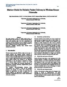
nodes. If a node broadcasts a packet and all its six neighbours heard it, then the number of received packets will be incremented by six. Upon receiving a packet, a node performs a check based on criteria shown in TABLE II. If the packet is a duplicate, the node discards it. The ‘duplicates’ curve shows the number of such discarded packets. The effectiveness of the duplicate avoidance is evident from the number of packets received and the number of packets being detected as duplicates, which are not being relayed. This contributes to the energy efficiency of our scheme. Next, we study the robustness of packet delivery of the packet cloning in terms of the PDR under varying channel quality. As shown in Figure 7, the PDR is sustained at close to 100% as the link quality deteriorates, indicated by the increasing PLR. With two clones, our method can generate sustain high packet delivery ratio for per hop packet loss of up to 40%. Similarly, high PDR is achieved with three clones under losses of up to 60%. By adding another clone giving a total of four, high PDR can be further sustained for additional 10% loss. The trend is logical and further increase in the number of clones will not achieve much incremental performance improvement.
Sink
Source Figure 9. Network topology for validation
The density of nodes in the network is determined by the average degree of connectivity (the number of connected neighbours per node) which is set to be between four and six. We assume a homogeneous network of nodes, each with a transmission range of 250m, and nodes are uniformly deployed over the network, giving a total of up to 40. The source and sink nodes are located at the two ends of the network as shown in the figure, and the average number of hops from source to sink is 10. The physical layer is a typical acoustic channel with propagation delay of 1500m/s, spherical path loss model, constant shadowing model and Rayleigh fading [6]. The raw transmission data rate is 5000bps which is common for commercially available acoustic modems, and the medium access control scheme is based on a simple carrier-sense multiple access (CSMA) method. The source sends 5000 packets to the sink at 100 second intervals using different numbers of clones, from two to four. We varied the packet loss ratio (PLR) per link from 0% to 100% in steps of 10% and studied two key performance metrics, namely, the total number of transmissions needed to deliver a packet from source to sink and the packet delivery ratio (PDR). The number of transmissions per packet (broadcast at the link layer) essentially translates to the energy consumption. In Figure 8, we show the energy efficiency of packet cloning for the two-clone scenario. The ‘transmitted’ curve represents the number of transmissions by nodes relaying the packets. When the PLR is 0% indicating that the channel is ideal, the two clones are transmitted over the 10 hops without loss, thus the overall number of transmissions per packet is 20. The increase in the number of transmissions for the range of PLR values between 10% and 60% is caused by packet losses. A broadcast may not be received by neighbouring nodes, and these nodes may also not hear their neighbors subsequently relaying the packet. After the timeout period has expired, one such node regenerates the clone that it thought was lost and transmits it, only to be discarded by the other nodes. The fast drop of transmissions when the PLR exceeds 60% is also caused by packet loss. In this case, the loss is so severe that the packet delivery process fails midway and this can be seen in the results for the PDR. The ‘received’ curve shows the number of transmissions received by the
Number of packets
120
Packet Delivery Ratio
1
20 80 40 60 Packet Loss Ratio (%)
0
20
40 60 80 Packet Loss Ratio (%)
100
B. Related Work There have been relatively few routing protocols specifically designed for underwater networks using wireless communications. Most operational underwater networks in existence are connected by cabled links. There are also adaptations of existing terrestrial mobile ad hoc network routing protocols for use in underwater scenarios, and examples of these include AODV-BI [7], COFSNET and AUSNET [8]. In the Seaweb acoustic networks, optimum routes are
40
20
0.2
Another key benefit provided by our packet cloning approach is the resilience to the link quality fluctuation. The packet delivery ratio is not gradually degrading increasing the per-hop-loss ratio. It sustains high PDR for as long as possible until it reaches a threshold, beyond which the PDR drop rapidly. In the underwater acoustic channel, link quality fluctuations occur frequently and therefore it is important for a data delivery scheme to be able to sustain high PDR consistently. This behaviour is useful for developing an adaptation scheme to dynamically vary the number of clones used when the link PLR crosses certain thresholds.
60
0
2 clone 3 clone 4 clone
0.4
Figure 7. Robustness of Packet Cloning
80
0
0.6
0
transmitted received duplicates
100
0.8
100
Figure 8. Energy efficiency of Packet Cloning
39
Packet Delivery Ratio
determined using a genetic-algorithm based routing protocol [9] during the network initialization phase, while the FRONT project, which deployed an underwater network and conducted experiments in shallow waters of depth from 26m to 51m, manually reconfigures routing by sending a sequence of commands from shore via a gateway node [10]. The Vector-Based Forwarding (VBF) routing protocol [11] is a position-based approach in which nodes in the proximity of the vector connecting the source to the sink forward packets. While the complex computations required by VBF can be handled by the much larger underwater sensors, it also requires distance and signal angle-of-arrival (AoA) information, which is not easily available in practical scenarios, even from acoustic directional antennas. Nevertheless, it serves as a worthy benchmark protocol for us to compare against.
1 0.9 0.8 0.7 0.6 0.5 0.4 0.3 0.2 0.1 0
0.1 0.2 0.3 0.4 0.5 0.6 0.7 0.8 0.9 512
648
729
810 900 1000 1100 1210 Network Size
Packet Delivery Ratio
(a) Packet cloning
C. Performance Benchmarking We implemented both VBF and our packet cloning protocols in QualNet [12]. The physical layer parameters remain unchanged from the simulations used in the validation of our packet cloning protocol. A key difference lies in the topology, which is now a three-dimensional network of 1000m×1000m×1000m. Data packets have a network layer 76-octet payload which includes the header for the routing protocols. Our performance metric of focus is PDR. While there are other metrics of interest, like latency and overheads, we felt that under the harsh underwater conditions, the first priority would be to ensure that packets get delivered. The overheads would directly affect the PDR as they contend with the data packets for the scarce channel bandwidth. As for the latency, the underwater propagation delay is subjected to the physical constraints of the speed of sound at 1500m/s. Even with real-time delivery requirements, it cannot realistically be faster than the speed of sound. Besides, due to the temporal fluctuations in link quality and channel blackouts, it is often more viable to buffer packets and wait for the channel to recover before forwarding them. An underwater network can be viewed as a challenged internet that is suitable for delay-tolerant networking methods [13]. We study the effect of the node density in the network on the PDR. Results for our scheme using two clones and VBF are shown in Figure 10. When the network is denser, the probability of packet delivery increases but at the same time, the contention also increases as there are more neighbours per node. We also vary the link quality of the network, from the ideal case of no loss to the case of 90% PLR. Each simulation scenario is repeated 20 times with different seed values. For good link quality of PLR up to 30% both packet cloning and VBF are comparable. As the PLR gets worse, up to 60%, packet cloning is able to maintain close to 100% PDR as it regenerates packet clones that are deemed loss. As for VBF, packets that are lost are not recovered by the scheme. Even with PLR of up to 80%, as long as the node density is sufficient for some nodes to overhear one another’s transmissions, lost packet clones can be regenerated and transmitted, thus ensuring a high PDR. If the subsequent nodes detect these as duplicates, they simply discard them without adding any extra overheads to the network and consuming more energy (as shown previously in Figure 8). Hence, we are able to achieve higher PDR under different link conditions.
1 0.9 0.8 0.7 0.6 0.5 0.4 0.3 0.2 0.1 0
0.1 0.2 0.3 0.4 0.5 0.6 0.7 0.8 0.9 512
648
729
810
900 1000 1100 1210
Netw ork Size
(b) VBF Figure 10. Comparison of PDR VI. IMPLEMENTATION ISSUES A. Belt Forwarding Region The basic idea provides data delivery capability over a ‘belt’ region. In a practical deployment scenario, we need to create a belt to restrict the flooding process, in order to prevent the broadcasting from turning into a full-scale flooding involving many irrelevant nodes and wasting energy. We need to create a belt from source to sink, as shown in Figure 11a. The belts need not be ‘straight’ and there can also be multiple belts between a pair of source and sink for further redundancy and robustness. For each belt, we use packet cloning scheme for packet delivery. To create the belt, we first find paths to one or more sinks [14], and then widen the paths to form a belt. Similar to a route discovery process in mobile ad hoc network, the sink does a one-time broadcast; each node will record its hop count towards the sink, and do at least one relay of the broadcast with its own hop count value inside the packet. In this manner, a node knows its neighbors’ hop counts, and thus the logical distance that sink. This process can also be used to announce the sinks geographical location which may be used later. Belt forming is done by forwarding a packet from a source to sink. For an intermediate node with hop count n, it can forward a packet to any one of its neighbors that has hop count less than n. The path is widened by including one-hop (or k-hop) neighbors. In Figure 11b, when node A with hop count n receives a packet for forwarding, it randomly chooses a neighbor with hop count n-1. In its broadcast packet, it indicates that node A and node B are the center of the path. Node A’s neighbors, G and H, will
40
sink
contention and energy expenditure. Using simulations, we validated our scheme and compared with one of few existing routing schemes for underwater sensor networks and showed that we are able to achieve high packet delivery ratio, even when link quality is poor and up to 60% of transmissions may be lost. As part of our ongoing work, this scheme is being implemented for field tests in shallow waters of up to 50m in depth.
sink
source
REFERENCES
a) Belts in a deployment region hop n-3
[1] J. Catipovic, “Performance Limitations in Underwater Acoustic Telemetry,” IEEE Journal of Oceanic Engineering, vol. 15, pp. 205–216, Jul 1990. [2] D. B. Kilfoyle and A. B. Baggeroer, “The State of the Art in Underwater Acoustic Telemetry,” IEEE Journal of Oceanic Engineering, vol. 25, pp. 4–27, Jan 2000. [3] M. Haenggi and D. Puccinelli, “Routing in Ad Hoc Networks: A Case for Long Hops,” IEEE Magazine, vol. 93, no. 10, pp. 93-101, Oct 2005. [4] C. Intanagonwiwat, et al., “Directed diffusion for wireless sensor networking,” IEEE/ACM Transactions on Networking, vol. 11, no. 1, pp. 2-16, Feb 2003. [5] H. Füβler, et al., “Contention-Based Forwarding for Mobile Ad-Hoc Networks”, Ad-Hoc Networks, vol. 1, no. 4, pp. 351-369, Nov 2003. [6] X. Lurton, An Introduction to Underwater Acoustics: Principles and Applications, Springer-Verlag Berlin and Heidelberg GmbH & Co. K, Oct 2002. [7] K. Y. Foo, et al., “A Routing and Channel-Access Approach for an Ad Hoc Underwater Acoustic Network”, Proc. of OES/IEEE TECHNO-OCEANS Conference, Kobe, Japan, Nov 9-12, 2004. [8] C. Benton, et al., “Autonomous Undersea Systems Network (AUSNET) - Protocols to Support Ad-Hoc AUV Communications”, Proceedings of the IEEE/OES AUV2004: A Workshop on Multiple Autonomous Underwater Vehicle Operations, Sebasco Estates, ME, USA, June 12-14, 2004. [9] E.M. Sozer, M. Stojanovic and J.G. Proakis, “Initialization and Routing Optimization for Ad Hoc Underwater Acoustic Networks”, Proceedings of Opnetwork, Washington, DC, USA, Aug 2000. [10] D. L. Codiga, J. A. Rice and P. A. Baxley, “Networked Acoustic Modems for Real-Time Data Delivery from Distributed Subsurface Instruments in the Coastal Ocean: Initial System Development and Performance”, Journal of Atmospheric and Oceanic Technology, vol. 21, no. 2, pp. 331-346, Feb 2004. [11] P.Xie, J. H. Cui and L. Lao, “VBF: Vector-Based Forwarding Protocol for Underwater Sensor Networks”, Proceedings of IFIP Networking, Coimbra, Portugal, May 15-19, 2006. [12] Scalable Networks, Inc., QualNet simulator, http://www.qualnet.com. [13] K. Fall, “A Delay-Tolerant Network Architecture for Challenged Internets”, Proceedings of SIGCOMM’03, Karlsrhue, Germany, Aug 25-29, 2003. [14] W. K. G. Seah and H.P. Tan, “Multipath Virtual Sink Architecture for Wireless Sensor Networks in Harsh Environments”, invited paper, Proceedings of 1st Int’l Conference on Integrated Internet, Ad Hoc and Sensor Networks (InterSense), Nice, France, May 29-31, 2006.
D
hop n-2
C
hop n-1
E
hop n
G
B A
F H
b) Belt forming from single path Figure 11. Belt formation strategy know that they are included in the belt. When B relays the packet, nodes E and F will also be included in the belt. Forming belt region from source to sink is not a repetitive process, and its energy cost is offset by the subsequent usage of the belt. B. Optimal number of clones The number of clones used will obviously affect the energy costs. With good link quality, fewer clones are needed while more clones are required when the channel conditions are poor. Similarly, more clones can be used if the packet is critical and its delivery needs to be assured. Dynamic adaptation of the number of clones can be done by getting periodic feedback from the sink on the proportion of clones it received. Also, the source can explicitly ask for feedback from sink, when it deems necessary. If the source finds that the sink has been receiving too many clones, it will reduce the number of clones per packet, and inversely, if a source expecting feedback from a sink does not receive it within the expected timeframe, it then assumes that packet losses are higher previously perceived and increases the number of clones for its subsequent packets to be transmitted. VII. CONCLUSIONS In this paper, we first discussed the challenges presented by the harsh underwater environment, and the problems and issues associated with underwater wireless networking using acoustic communications. We then presented a data delivery scheme that exploits the broadcast nature of wireless links to selectively clone packets as they are forwarded to the sink. Unlike controlled broadcast or conventional multipath routing where duplicated packets are indistinguishable and nodes have no means of determining how many duplicates have been introduced into the network, our scheme is able to control the number of packet clones according to the channel conditions and link quality so as to improve the probability of successful delivery while minimizing
41