Efficient Design of Two-Stage Comb-based Decimation Filters using Chebyshev Sharpening Massimiliano Laddomada
David Ernesto Troncoso Romero, Gordana Jovanovic Dolecek
Electrical Engineering Department Texas A&M University – Texarkana Texarkana TX 75505, USA
[email protected]
Electronics Department Institute INAOE Tonantzintla Puebla 72840, México
[email protected],
[email protected] Abstract— A simple and efficient method to design multiplierless two-stage comb-based decimation filters is presented. The proposed scheme takes advantage of the Chebyshev sharpening, recently introduced in literature, to obtain higher selectivity in comparison to traditional comb filters. The resulting filter has better magnitude response characteristics and fewer Additions Per Output Sample (APOS) with respect to other two-stage comb-based filters available in literature.
I. INTRODUCTION The decimation process is often realized in several stages. The passband of the first-stage filter in the decimation chain, Xp, and its k-th stopband (k-th folding band), Xs,k, are
X p = [0, X s , k = [ 2Mkπ − Mα ⋅⋅πR ,
2 kπ M
α ⋅π M ⋅R
],
(1)
+ Mα ⋅⋅πR ], with k = 1, 2,..., ⎢⎣ M / 2 ⎥⎦ , (2)
where D = M ⋅ R, M and R are, respectively, the total, firststage and residual decimation factors, and α is a real constant with 0 < α ≤ 1. The comb filter, with transfer function H ( z ) = (1 − z − M ) /(1 − z −1 ) = ∑ i = 0 z −i , M −1
(3)
is commonly used in the first stage of the decimation chain because of two main reasons [1]: 1) it does not require either multipliers or coefficients storage (H(z) is scaled by 1/M to provide unitary gain at zero frequency) and 2) its zeros are centered in the folding bands. However, its magnitude response exhibits a passband droop and poor attenuation in the stopbands. The attenuation can be increased by implementing K comb filters in cascade but the passband droop increases. Moreover, the Worst-Case Passband and Attenuation Values (respectively WCPV and WCAV) occur in the right end of the passband and in the left end of the first folding band. The Cascaded Integrator Comb (CIC) structure, introduced by Hogenauer in [1], is efficient in terms of chip area but requires integrators working at high rate, thus having high power consumption. Because of this, two-stage comb-based decimation schemes have gained great popularity [2]-[11]. In these cases the decimation by M is split between two separated
978-1-4799-0066-4/13/$31.00 ©2013 IEEE
downsampling blocks M1 and M2, where M=M1M2. The transfer function of the decimation filter is H TS ( z ) = H1K1 ( z ) ⋅ H 2K2 ( z M1 ) ,
(4)
where H1(z) and H2(z) are the transfer functions of combbased filters. The first-stage comb-based filter H1K1(z) is designed in non-recursive form and can be implemented at lower rate, after the downsampling by M1, by polyphase decomposition. This results in lower power consumption at expense of area usage increase. The filter H2K2(zM1) is moved after the downsampling by M1 using multirate identities and the resulting second-stage comb-based filter exploits the CIClike structure for modest demand of area. In this way, the overall filtering scheme achieves a trade-off between power and area consumptions by properly choosing M1 and M2 (usually M1 ≤ M2). It has been observed that, if HTS(z) = HK(z) (which can be obtained from (4) by expressing H1(z) and H2(z) with (3), respectively replacing M by M1 and M2, and setting K1=K2=K), the WCPV and WCAV are mostly determined by the secondstage filter. Thus, this filter is usually an improved-magnitude version of a traditional comb filter, whereas the first-stage filter is preserved as a comb cascaded K1 times. For example, in [2], [3] and [7] the second-stage comb filter is improved using the well-know Kaiser-Hamming Sharpening (KHS) of [12]. In [5], this filter is previously compensated using the compensation filter from [13] and then KHS is applied to it. In [8] the compensation filter is applied after using KHS. The method [11] applies the general sharpening from [14]-[15] to a previously compensated (with a compensator from [13]) second-stage comb and it exhibits better results in comparison to [2], [3], [5] and [8]. Methods [4] and [9] only improve the WCAV of the second-stage comb filter with the zero-rotation scheme introduced in [16], and decrease the passband droop by using compensation filters. The zero-rotation can be implemented with multiplierless recursive structures as shown in [17], but the required wordlengths are generally very large. In [9] this was solved by using a non-recursive zero-rotation filtering. However, the value M2 must be equal to 2 and, since the value M1 increases as M increases, the sought trade-off between power and area consumptions is unbalanced. A
1011
Inspired by the works [4], [6], [9]-[10] and the characteristics of Chebyshev-Comb Filters (CCFs), recently introduced in [19] and briefly revised in Section II, in Section III of this paper we introduce a simple and efficient method to design two-stage CCF-based decimation filters. The proposed scheme consists of preserving the first-stage filter as a traditional comb and using a CCF in the second stage, whereas the passband droop is corrected with compensation filtering. The discussion of results is addressed in Section IV. Finally, Section V presents our conclusion. II. CHEBYSHEV-COMB FILTERS An N-th order Chebyshev-Comb Filter (CCF) is a comb filter sharpened by a Chebyshev polynomial of first kind whose degree is N [19]. Its transfer function is given by H C , N ( z ) = ∑ i = 0 z − ( N −i ) M / 2 ⋅ ci ⋅ [γ z −1 H ( z )]i , N
(5)
where ci is the i-th coefficient of the polynomial, i.e., we are using the notation P(x) = c0 + c1x + … + cN–1xN–1 + cNxN for a Chebyshev polynomial of degree N. The factor γ,
γ ≤ γ max = 1/ H ( z ) z = e ω , ω x = j x
2π M
− Mα ⋅⋅πR ,
(6)
must be expressible in Sum Of Powers Of Two (SOPOT). The following are important characteristics of an N-th order CCF in comparison to a cascaded-by-N comb filter [19]: 1) HC,N(z) and HN(z) have similar passband droops, but the WCAV of HC,N(z) is improved (i.e., it is greater) by approximately 6(N–1) dB in comparison to the corresponding WCAV of HN(z). N
2) Unlike H (z), where the WCAV appears in the left-hand side of the first stopband, in HC,N(z) this value may appear in every stopband (this occurs also in method [20]). 3) The CIC-like structure introduced in [20] can be used for decimation applications (as proposed in [19]). The structure is multiplierless, it does not suffer of pole-zero cancelation issues and it has modest extra computational complexity compared with the CIC structure.
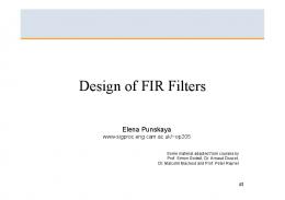
M, since the shape of the magnitude response of these combbased filters change very little with M. We observe that, for a given R, the WCAV of an N-th order CCF is equal or greater than the WCAV of a cascaded-by-(N+1) comb if the value N is equal or higher than a lower bound Nmin, and Nmin decreases as R decreases. For example, if R = 9, we have that the WCAV of both, HC,N(z) and HN+1(z), is 150 dB when N = Nmin = 5 (Fig. 1b). On the other hand, if R = 2, the WCAV of both is about 40 dB when N = Nmin = 3 (Fig. 1a). Clearly, it is convenient to use an N-th order CCF instead of a cascaded-by-(N+1) comb if the WCAV is high enough to demand N ≥ Nmin because the former requires fewer cascaded comb filters than the latter. We formalized the aforementioned discussion with the following formulation. Given a prescribed WCAV in dB, denoted as Amin, we propose to obtain the number of cascaded comb filters necessary to achieve a WCAV equal to Amin as
K e = ⎡⎢ − Amin / 20 log10 { M1 | H ( z ) |z = e jωx }⎤⎥ , ω x =
(
lmax = ⎢6 K e / 6 − 20 log10 ⎣
{
1 M
H ( z ) z = e jωx
})⎥⎦ , ω
x
=
2π M
− Mα ⋅⋅πR . (8)
1) In the first-stage decimation block, i.e., a filter H1K1(z) (the transfer function is referred to the input sampling rate) followed by a downsampler by M1, the residual decimation factor is R1 = M2R. Let us assume that H1(z) is a comb filter. 0
K = 1, N = 1
20 K = 2, N = 2
40 K=3
60
N=3
80
K=4
100 120
Comb CCF
140 2
3
Worst-Case Attenuation Value (dB)
A. When to use CCFs as first- and second-stage filters Let us start with Figures 1a and 1b that show the WCAVs (in dB) for N-th order CCFs and cascaded-by-K comb filters against R, when M = 16. The figures can be used regardless of
− Mα ⋅⋅πR . (7)
If lmax ≥ 1, it is convenient to use the Nmin-th order CCF instead of the cascaded-by-Ke comb. Now, let us consider the following observations:
N = 4, K = 5 4
III. PROPOSED SCHEME In this section we introduce the proposed two-stage CCFbased decimation scheme. To this end, in subsection III-A we first address the problem to decide whether or not using a CCF in both, the first and the second stage. The design of the compensation filter is introduced in subsection III-B. The final structure is given in subsection III-C and subsection III-D shows how to choose the design parameters.
2π M
Since an N-th order CCF may replace a cascaded-by-Ke comb filter to achieve the same WCAV, we express the order of the CCF as N=(Ke–l). For the highest possible integer l, which we call lmax, N becomes equal to Nmin. We calculate lmax as
Worst-Case Attenuation Value (dB)
similar but more efficient approach is followed in [6] and [10] (method [10] is focused on the cases where R = 2), where the stopband characteristic is improved by increasing the number of cascaded filters, K2. The compensators used in [6] and [10] are, respectively, based on methods [13] and [18].
5 6 7 8 Residual decimation factor, R (a)
50 K = 6, N = 5
100
K = 7, N = 6
K=8
9
10
Comb CCF
150 200 K = 9, 250 N = 7
K = 10, N=8
N=9
N = 10 5 6 7 8 9 10 Residual decimation factor, R (b) Fig. 1: Worst-Case Attenuation Values (WCAVs) of HC,N(z) and HK(z) vs R.
1012
300 2
3
4
Replacing M by M1 and R by R1 in (7) and (8), we have that lmax is, for most typical values of M1, R1 and Amin, always less than 1. 2) In the second-stage decimation block, i.e., a filter H2K2(z) (the transfer function is referred to the downsampled-by-M1 sampling rate) followed by a downsampler by M2, the residual decimation factor is R2 = R. Assuming that H2(z) is a comb filter and substituting M by M2 and R by R2 in (7) and (8), we have that lmax is, for most typical values of M2, R2 and Amin, always equal or greater than 1. From the previous observations, we propose to use an Nminth order CCF as second-stage filter, whereas the first-stage filter is preserved as a cascaded-by-K1 traditional comb. B. Compensation filter design The passband droop of the filter HTS(z) is mainly dominated by the passband droop of the second-stage filter [6], [10]. Additionally, the passband droop of an N-th order CCF is similar to that of a cascaded-by-N comb. Since the proposed second-stage filter is an Nmin-th order CCF, we can use a compensator designed for a cascaded-by-Nmin comb filter. Thus, at first glance, any compensation filter designed for such comb would work. However, in this paper we use Lth order Type-I (i.e., symmetrical) Finite Impulse Response (FIR) compensation filters whose vector of coefficients, g*, solves the minimax optimization problem
g* = arg min g {ε (g)} ,
g is SOPOT expressible,
ε (g ) = max 1 − G (ω , g) S1 S2 H1K ( z ) H C , N ( z M ) απ 1
ω≤
R
1
min
z = e jω / M
(9a) , (9b)
where G(ω,g) is the amplitude response of the compensator, referred to the downsampled-by-M sampling rate, whereas S1 and S2 are the respective scaling for |H1K1(z)|z=ejω/M and |HC,Nmin(zM1)|z=ejω/M to make them equal to 1 when ω = 0. More details on the design of compensation filters under the minimax criterion are given in [21]. The authors in that reference use Interval Analysis to solve the optimization problem (9). Here we employ the Mixed Integer Linear Programming (MILP) using the Matlab routine available in [22], which is based on the Matlab function linprog. C. Final two-stage structure The transfer function of the proposed two-stage combbased decimation filter is
H p ( z ) = H1K1 ( z ) ⋅ H C , N min ( z M1 ) ⋅ G ( z M1 M 2 ) ,
(10)
where H1(z) is given in (3), upon replacing M by M1, HC,Nmin(z) is given in (5), upon replacing N by Nmin and M by M2, and G(z) denotes the transfer function of the compensation filter (referred to the downsampled-by-M sampling rate). To get a normalized magnitude with 0 dB in ω = 0, the scaling S1S2 must be introduced (as explained in the previous subsection). Figure 2 shows the resulting structure after expressing H1K1(z) in non-recursive form and decomposing it in polyphase components, which are denoted as Pi(z), with i = 1, 2, .., M1. The filter HC,Nmin(z) is implemented using the CIC-like structure proposed in [20]. However, the slight modification
with regard to the distribution of coefficients based on the Horner-algorithm form, as proposed in [19], can also be used. In Fig. 2, we have A(z) = z–1/(1–z–1) and B(z) = 1–z–1. The coefficients di, i = 0, 1, …, D, with D=(Nmin–v)/2, are obtained as di = c2i + v, with v = 1 if Nmin is odd or v = 0 if Nmin is even. The dotted blocks are bypassed if Nmin is even. D. Choice of the design parameters We consider that α, R, M and the desired attenuation Amin are a priori given. The design parameters are M1, M2 (factors of M), K1, Nmin and γ. We calculate M1 and M2 as explained in [6], [10], i.e., making them close in values as much as possible to each other with M1 ≤ M2. K1 is estimated using (7) upon replacing M by M1 and R by R1 = M2R. We estimate Nmin as K2–lmax. To this end, K2 is calculated with (7), upon replacing M by M2, and lmax is calculated using (8), upon replacing M by M2 and Ke by K2. Finally, γ is obtained as γ = 2−6 ⎢⎣γ max / 2−6 ⎥⎦ , where γmax is obtained from (6), upon replacing M by M2. It is worth highlighting that, since the proposed scheme includes compensation, the estimated values K1 and Nmin may not be enough to achieve the attenuation Amin and, in that case, they must be increased accordingly. With regard to the design of the compensators, we use an order L=4 and a word-length equal to 5 for the fractional part of the coefficients. IV. DISCUSSION OF RESULTS In the following we use a couple of examples to compare our method with references [6] (or [10] when R = 2) and [11], which present the best trade-off in terms of computational complexity (quantified in Additions Per Output Sample, APOS) and magnitude-response improvement. In both examples we assume, in according to [6] and [10], that the same attenuation is desired in all the stopbands. Example 1: Consider M = 21, R = 2, Amin = 96dB and α=1.
The values M1, M2, K1, Nmin and γ are calculated as explained in Section III-D. We get M1=3, M2=7, K1=4, Nmin=7 and γ=2–6 × 29 (γ2=2–12 × 841). The compensation filter has the transfer function G(z) = 2–5 × 5 × (1–z–4) –2–5 × 28 × ( z–1–z–3) +2–5 × 78 × z–2. The coefficients from the Chebyshev polynomial are d0 = –7, d1 = 56, d2 = –112, d3 = 64. Both methods, [10] and [11], use also K1 = 4 for their firststage comb filter. The second-stage comb filter is cascaded by K2=11 in method [10] and by K2=2 in method [11]. Additionally, in [11] is used the compensator G1(z) = –2–3[1– (23+2)z–1+z–2] (transfer function referred to downsampled-byM sampling rate) and the compensated comb is sharpened with the polynomial P(x) = 2–1 × 13x6 – 2–1 × 11x7 (σ =2–1, δ=0, M1 z–1 .. . z–1
M1
M1
P1(z)
+
P2(z)
–D
.. .
z
M2
.. . γ
B(z)
+
γ2
d1
A2(z) –1
z
…
M2 …
z–(D–1)
z d0
A2(z)
M2
–D
PM1(z) G(z)
–(D–1)
z
+
…
A2(z)
A(z)
2
M2
–1
z dD–1
γ B2(z) + … B2(z) +
γ2
dD B2(z)
Fig. 2: Proposed structure. The dotted blocks are included if Nmin is odd.
1013
0
Gain (dB)
-50
1
TABLE I. COMPARISON OF RESULTS IN TERMS OF APOS AND WORST-CASE MAGNITUDE VALUES
Method [10] Method [11] Proposed
Passband Detail
WCPV (dB) WCAV (dB) APOS
0 -1 0
0.01
0.02
-100
-150 0
0.2
0.4
ω/π
0.6
0.8
1
Fig. 3: Magnitude response of filters from Example 1.
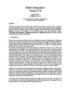
m = 1, n = 5, using the notation from [11] and [15]). The transfer function of the compensator employed in [10], referred to the downsampled-by-M sampling rate, is G2(z) = [–2–4{1–(24+2)z–1+z–2}]10. Figure 3 shows the magnitude response of the proposed filter compared with the magnitude of the filters obtained using methods [10] and [11]. Table I summarizes the absolute WCPVs and WCAVs along with the APOS for every design. Example 2: Consider M = 85, R = 4, Amin=120dB and α=1.
Following the explanation of Section III.D, we get M1=5, M2=17, K1=3, Nmin=6 and γ=2–5 × 13 (γ2=2–10 × 169). The transfer function of the compensation filter is G(z)=2–4 × 1 × (1–z–4)–2–4 × 8 × (z–1–z–3)+2–4 × 30 × z–2. The coefficients from the Chebyshev polynomial are d0 = –1, d1 = 18, d2 = –48, d3 = 32. For method [6], we have K1 = 3, K2=8 and G2(z) = –2–1(1–22z–1+z–2). For method [11] we have K1=3, K2=2, G1(z)= –2–3[1–(23+2)z–1+z–2] and the sharpening polynomial is P(x)=2–3 × 39x4 – 2–3 × 31x5 (σ = 2–3, δ=0, m = 1, n = 3). Table I shows the absolute WCPV, WCAV and APOS of methods [6], [11] and proposed. Since in both examples all the methods use the same first-stage filter, the number of APOS in Table I does not account for the first-stage filter. Note that the proposed method has less complexity than [6], [10] and [11], whereas its magnitude characteristics are very similar to method [11] and better than methods [6] and [10]. V. CONCLUDING REMARKS This paper has presented an efficient method to design two-stage comb-based decimation filters. The proposed filtering scheme shows that using both, CCFs in the second stage and compensation filtering at lower rate, results in better magnitude characteristics and performs fewer APOS than other two-stage comb-based methods, mainly when the residual factor R is low (i.e., less or equal than 4). REFERENCES [1] E. B. Hogenauer, “An economical class of digital filters for decimation and interpolation,” IEEE Trans. Acoust. Speech and Signal Processing, vol. ASSP-29, no. 2, pp. 155-162, April 1981. [2] G. Stephen and R. Stuart, “High-speed sharpening of decimating CIC filter,” Electronics Letters, vol. 40, No. 21, pp. 1383-1384, Oct. 2004.
[10]
Example 1 Methods [11] Proposed
0.95
0.07
0.14
0.44
0.016
0.011
103
97.5
99.5
135
121
130
118
136
84
146
199
127
[6]
Example 2 Methods [11] Proposed
[3] G. J. Dolecek and S. K. Mitra, “A new two-stage sharpened comb decimator,” IEEE Trans. Circ. Syst. –I: Reg. Papers, vol. 52, No. 7, pp. 1416–1420, July 2005. [4] G. J. Dolecek, “A new modified comb-rotated sinc (RS) decimator with improved magnitude response,” in Proc. 14th IEEE ICECS 2007, Marrakech, Morocco, pp. 250–253, Dec. 11-14, 2007. [5] G. Dolecek and F. Harris, “On design of two-stage CIC compensation filter,” in Proc. IEEE Int. Symp. Industrial Electronics, pp. 903–908, Jul. 2009. [6] G. J. Dolecek and S. K. Mitra, “Two-stage CIC-based decimator with improved characteristics,” IET Signal Process., vol. 4, No. 1, pp. 22-29, Jan. 2010. [7] N. R. Karnati, K. S. Lee, J. Carletta and R. Veillette, “A power-efficient polyphase sharpened CIC filter for Sigma-Delta ADCs,” in Proc. 54th IEEE MWSCAS 2011, Seoul, Korea, pp. 1-4, Aug 7-10, 2011. [8] H. Zaimin, et al, “A novel CIC decimation filter for GNSS receiver based on software defined radio,” in Proc. 7th IEEE Int. Conf. WiCOM 2011, pp. 1-4, Wuhan, China, Sep. 23-25, 2011. [9] G. J. Dolecek and M. Laddomada, “A novel two-stage nonrecursive architecture for the design of Generalized Comb Filters,” Digital Signal Processing, Elsevier, vol. 22, pp. 859-868, September 2012. [10] G. J. Dolecek and S. K. Mitra, “Novel two-stage comb decimator,” Computación y Sistemas, vol. 16, no. 4, pp. 481-489, Dec. 2012. [11] M. G. C. Jimenez and G. J. Dolecek, “Application of generalized sharpening technique for two-stage comb decimator filter design,” Elsevier Procedia Technology, 3rd. Conference CIIECC, vol. 7, pp. 142-149, 2013. [12] F. Kaiser and R. Hamming, “Sharpening the response of a symmetric nonrecursive filter by multiple use of the same filter,” IEEE Trans. Acoust., Speech, Signal Process. vol. ASSP-25, pp. 415-422. 1977. [13] G. J. Dolecek and S. K. Mitra, “Simple method for compensation of CIC decimation filter,” Electronics Letters, vol. 44, No. 19, pp. 1162–1163, Sep. 2008. [14] R . Hartnett and G. Boudreaux, “Improved filter sharpening,” IEEE Trans. on Signal Process. no. 43, pp. 2805-2810. 1995. [15] S. Samadi, “Explicit formula for improved filter sharpening polynomial,” IEEE Trans. on Signal Process. vol. 9, pp. 2957-2959. 2000. [16] L. Lo Presti, “Efficient modified sinc-filters for sigma delta AD converters,” IEEE Trans. Circ. Syst. –II, vol. 47, No. 11, pp. 12041213, Nov. 2000. [17] G. J. Dolecek and M. Laddomada, “An economical class of droopcompensated generalized comb filters: analysis and design,” IEEE Trans. Circ. Syst. –II: Express Briefs, vol. 57, No. 4, pp. 275–279, April 2010. [18] G. J. Dolecek, “Simple wideband CIC compensator,” Electronics Letters, vol.45, No. 24, pp. 1270–1272, Nov. 2009. [19] J. O. Coleman, “Chebyshev stopbands for CIC decimation filters and CIC-implemented array tapers in 1D and 2D,” IEEE Trans. Circ. Syst. I, vol. 59, no. 12, pp. 2956-2968, Dec. 2012. [20] T. Saramaki and T. Ritoniemi, “A modified comb filter structure for decimation,” in Proc. IEEE ISCAS 1997, pp. 2353-2356, June 9-12 1997. [21] M. G. Pecotic, G. Molnar and M. Vucic, “Design of CIC compensators with SPT coefficients based on interval analysis,” in Proc. The 35th IEEE Int. Convention MIPRO 2012, Opatija, Croatia, pp. 123–128, May 21-25, 2012. [22] S. Tawfik, MATLAB function to solve MILP problems, available online at http://www.mathworks.com/matlabcentral/fileexchange/6990-mixedinteger-lp/content/IP.m (last accessed, Mar. 29, 2013).
1014