Efficient Failure Recovery in Wireless Sensor Networks through Active Spare Designation Ketaki Vaidya and Mohamed Younis Department of Computer Science and Electrical Engineering University of Maryland, Baltimore County Baltimore, Maryland, USA ketvaid1,
[email protected] Abstract—In some applications a sensor network is composed of a set of mobile nodes deployed in an area of interest in order to collectively monitor suspicious activities, perform surveillance tasks, etc. Such collaboration needs frequent inter-node interaction and requires strong network connectivity. A sudden node failure may make nodes unreachable causing the network to partition. In addition, the loss of a node may result in a degraded coverage in certain area, and can thus negatively affect the network operation. Traditional recovery approaches pursue node repositioning upon the detection of the failure in order to reestablish connectivity. Unlike these reactive recovery approaches, this paper argues that some pre-failure planning would facilitate and expedite the recovery process. The idea is to find spare nodes inside a network, prior to the failure that can volunteer to replace the failed node. Identification of spare nodes is done based upon coverage overlap and node degree. A spare node is designated based on the contribution of a node to the network coverage and connectivity. When a failure is detected, the most suitable active spare is called to replace the dead node and the network topology is adjusted through a series of cascaded motion. The proposed approach is validated through simulation.
I. INTRODUCTION The interest in Wireless Sensor Networks (WSNs) is mainly fueled by the many applications that can be leveraged by WSNs [1]. In a typical WSN, a set of sensor nodes is employed to collectively monitor an area of interest and track events or phenomena. After deployment nodes form a network in an ad-hoc manner and collaborate in executing task. To enable coordination and data sharing, sensors need to be reachable to each other either through direct communication links or over multi hop paths. A sudden failure of a node can lead to serious disturbance in the network operation. Causes of node failure could be energy exhaustion or external damage due to the harsh surroundings. The loss of a node basically affects two important network attributes, namely, connectivity and area coverage. A node may be serving as a cut-vertex in the topology and the network becomes partitioned into disjoint blocks when such a node breaks down. Node failure can also degrade coverage in certain parts of the monitored area or leaves them totally without being probed. Therefore, sensors should be able to detect and recover from failures. Since WSNs are deployed in remote regions and operates autonomously, the recovery should be a self-healing process. Two methodologies for tolerating node failure are often considered. In the first, the recovery is simply provisioned during the network design by deploying redundant resources so that the network operation is sustained despite the loss of a
subset of the nodes [2]. Such approach would be hard to achieve at reasonable expenses in a remote area where deterministic node placement is not feasible. Therefore, provisioned solutions suit WSNs with stationary and inexpensive nodes. The second methodology is reactive in nature. Basically, the network is reconfigured to restore connectivity and mitigate any lost coverage after a node fails. This methodology applies for networks with nodes that are capable to move and often triggers a series of cascaded node relocation throughout the network [3-6]. This paper promotes a hybrid recovery methodology by combing the advantage of pre-failure planning and the avoidance of increased resource redundancy. Basically, nodes that are critical to the operation of the network are identified and spares are designated. The criticality of a node is determined based on its importance for maintaining strong network connectivity. For every critical node a backup is assigned among nearby nodes. Potential backups are qualified based on coverage redundancy and connectivity. A node that would cause the least coverage degradation would be favored. In addition, low node degree will make a node an attractive backup since limited cascaded relocation will be required. A novel distributed algorithm is proposed for implementing such a hybrid methodology. The proposed node recovery through active spare designation (NORAS) opts to localize the scope of the recovery by limiting the selection of backups to direct and 2-hop neighbors of a critical node. Upon detecting the failure of a critical node, the designated spare will travel to replace such a failed node or a series of cascaded relocation on the shortest route between the failed node and backup will be triggered to split the load on multiple nodes. NORAS is validated through simulation. The simulation results demonstrate the effectiveness of NORAS in terms of overhead and confirm its performance advantage over contemporary schemes found in the literature. The paper is organized as follows. Section II describes the assumed system model. Section III compares NORAS to previous work. NORAS is described in detail in Section IV. Validation experiments and performance analysis are provided in Section V. Finally, Section VI concludes the paper. II. SYSTEM MODEL AND PROBLEM STATEMENT The focus of this paper is on tolerating the failure of a critical node. The approach applies to a network of mobile sensor nodes or to the inter-actor topology of a sensor/actor network. Sensors collaborate with one another on executing tasks. To share data and coordinate their roles, upon deployment sensors
978-1-4244-8077-7/10/$26.00 2010 IEEE
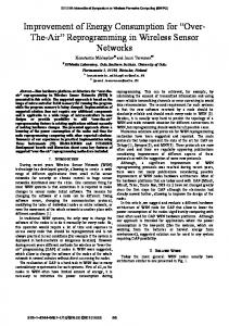
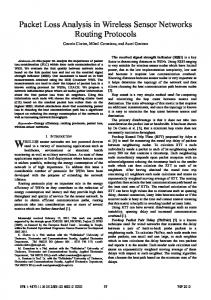
form a strongly connected network topology in an ad-hoc manner and establish multi-hop paths [2]. The communication range, Rc, of a node refers to the furthest point that the node’s transmission can be unambiguously received. Meanwhile, the sensing range, Rs, determines how far an event can happen and still gets detected by the node. A uniform sensing model is assumed, and thus the coverage of a node can be captured by a circle of radius Rs. The intersection of the areas within the range of multiple sensors is referred to as Coverage Overlap. For NORAS, nodes do not need to have identical sensing and communication ranges. However, for easing the presentation, we assume that all nodes in the network have identical Rc and Rs, respectively. A failure of a node may introduce a hole in the network coverage. In addition, the multi-hop inter-node communication paths can elevate the importance of some nodes. Basically, some nodes may act as cut-vertices in the network topology and thus the failure of any of these nodes would partition the network into multiple disjoint blocks e.g. Node 35 in Figure 1 NORAS pursues node relocation in order to restore connectivity severed by the failure of a cut-vertex node and minimize the loss of coverage. It is assumed that during the recovery process, there are no additional node failures. NORAS assumes that a node can determine its location relative to its neighbors [7]. Each node is assumed to maintain a list of its direct (1-hop) and 2-hop neighbors. This paper also deals with the recovery at the network layer, and assumes that neighbor discovery, link creation, maintenance and termination are handled by lower layers of the communication protocol stack. III. RELATED WORK To mitigate the effect of node failure, both avoidance and tolerance techniques have been explored in the literature. Avoidance techniques are provisioned solutions that deploy redundant resources so that the network operation is not interrupted when a node is lost. For example, Zhang, et al., [8] form a bi-connected network topology to keep the nodes linked even when a cut-vertex node fails. Meanwhile, Basu and Redi [9] rely on the pre-failure bi-connectivity in order to coordinate among healthy nodes during the recovery. On the other hand, tolerance techniques do not assume that the network is operational after a node fails and craft a recovery
Figure 1: Part of a Sensor Network showing a cut-vertex node 35. The failure of 35 will partition this network into 2 disjoint blocks.
plan accordingly [3-6,10,11]. In general, most prior efforts have focused on connectivity rather than coverage. As mentioned earlier, NORAS pursues a hybrid methodology that, like provisioned solutions, plans the recovery before the failure takes place, and avoids the deployment of redundant resources, similar to reactive solutions. Published recovery schemes can be further classified based on the objective. Preventing the presence of coverage holes is the objective of [3][11]. In [3], the communication range of nodes is assumed to be significantly larger than the sensing range and only increased coverage is targeted. The nodes are modeled as electro-magnetic particles and attraction and diffusion forces are applied to self-spread so that full coverage is restored. Meanwhile, both coverage and connectivity are considered in [11]. The idea is to trade-off spatial and temporal connectivity and coverage in order to minimize the effect of node failure on the network. Basically, neighboring nodes take turn in acting as substitutes by going to the position of the failed node. Unlike this approaches, NORAS opts to move a node from a highly covered area, i.e., has significant coverage overlap, in order to mitigate the any post-failure coverage hole. In addition, NORAS provides a stable solution for restoring connectivity, unlike C3R. On the other hand, a number of approaches have cared only about restoring lost connectivity without considering coverage. The idea is to reposition nodes in order to form a strongly connected topology. While DARA [4] and PADRA [5] replace the failed node, RIM [10] moves healthy nodes inward towards the location of the failure. The scope of node repositioning often spreads throughout the network in a cascaded manner and thus imposes significant overhead. NORAS opts to avoid that by limiting the scope to within 2 hop neighbors. Unlike the cascaded style of motion pursued in [4][5][10], nodes are moved in a coordinated manner as a block in [9]. However, this requires maintaining a biconnected topology at all times. IV. RECOVERY THROUGH ACTIVE SPARE DESIGNATION The failure of a node may partition a WSN into disjoint blocks and may leave certain part of the network uncovered. Unlike contemporary schemes in the literature, the proposed NORAS approach does a pre-failure recovery planning while staying reactive without requiring the deployment of redundant resources. The main idea is to designate a backup for every critical node in the network. Node degree and coverage overlap are considered while identifying the best suited spare nodes. Spares are active participants in the network and serve the application under normal conditions. Upon detection of the failure of a critical node, the network is reconfigured to restore connectivity and minimize the loss in field coverage. NORAS is described in detail in the balance of this section. A. Pre-Failure Recovery Planning NORAS does some preparation in order to enable recovery of a node failure. Basically, NORAS identifies critical nodes and finds for each of them Active Spare Nodes (ASNs), one of which is picked as backup. The entire process is distributed.
[Type text]
Self-Assessment: Once the network is formed, and after changes in the network topology, each node performs self assessment to determine whether it is an eligible ASN and can serve as a backup to other nodes in case of failure. The selfassessment is carried out through the following steps: 1. Identifying critical nodes: A node that acts as a cut-vertex is very important for the network since loss of such a node partitions the WSN. In order to determine whether a node is a cut-vertex, a depth-first search would be needed, which will implicitly requires knowing the structure of the entire WSN topology. Given the size of a typical WSN, it is thus impractical to use depth-first search. NORAS pursues a probabilistic approach for detecting cut-vertices. As mentioned earlier, every node maintains a table of its direct (Neighbor1-hop) and 2-hop neighbors (Neighbor2-hop). Such table will be used to assess whether the node is a cut-vertex by applying distributed algorithms like the one proposed in [12]. This type of algorithms generally trade off the need for a network-wide state with the accuracy of identifying cut-vertices. It has been shown that the probability of missing a cut-vertex is zero while most (≈90%) of the picked nodes are really cut-vertices. 2. Estimate availability as ASN: NORAS quantities the need for keeping a node in its position using an availability function. Basically, a node that should not move due to the essential role that it plays would have a low availability to serve as a backup to another node. A non-zero availability value qualifies a node to be an ASN. Obviously, a node Ac that acts as a cut-vertex should not serve as a backup. In fact, Ac is so crucial to the network connectivity that there has to be assigned a backup in case Ac fails. Cut-vertices will be referred to hereafter as critical nodes and will have availability of “-1” in order to disqualify them as ASN. The availability function factors in two metrics; namely, coverage and connectivity. A node may be a spare if there nodes in the vicinity that cover the area within its sensing range. This is factored in measuring the coverage overlap. Meanwhile, the node degree is used to capture the connectivity metric. Moving a node that has a high degree will affect many neighbors. Therefore, a node that has few neighbors should have a high availability value. The availability function for NORAS is as follows: Availability = α
+
β
The first term calculates the ratio of covered area relative to what a node would be able to cover. The second term relates the node degree to that of neighbors. The rationale is to make the availability measure unit less by normalizing the two considered factors. The parameters α and β are constants that can allow prioritizing the contribution of coverage and connectivity to the selection of backup nodes. Nodes with availability > 0 are considered ASNs. Designating Backup: Upon estimating its availability, each node informs its Neighbor1-hop and Neighbor2-hop. A critical node Ac will aggregate the availability of its neighbors and form ASN set from which one candidate is picked as a backup.
Starting with Neighbor1-hop, Ac will try to select a backup. The rationale is that direct neighbors are in close proximity and the travel overhead for a backup to replace Ac would be small. If none of Neighbor1-hop is a qualified ASN, Ac considers its Neighbor2-hop. If no ASN is among Neighbor1-hop and Neighbor2-hop of Ac, e.g. all direct and 2-hop neighbors of Ac are cut-vertices, the backup designation process proceeds in a transitive manner. Basically, Ac inquires about the selected backups of its Neighbor1-hop, and then Neighbor2-hop if needed, and picks the highest availability ASN among them as its own backup. In the rare case when there is no eligible ASN, which happens when a series of cut-vertices exists in the network, a backup will be identified after node Ac fails. Pre-Failure-Assessment() // Every node performs self-assessment of level of critically 1. IF (I am a cut-vertex) 2. My_Availability=-1 3. Inform neighbors about my availability 4. DesignateBackup () 5. ELSE 6. Calculate Overlapped coverage 7. NDR = Node Degree/(Avg node degree of neighbors) 8. Availability = α . Overlapped coverage + β . NDR 9. Inform neighbors about my availability 10. ENDIF DesignateBackup () // Nodes with Availability=-1 undergo DesignateBackup(), while nodes with Availability > 0 becomes Active Spares. 11. My.Backup = ϕ 12. Candidates = Neighbor1-hop 13. Repeat 14. IF ( ∃ node i ∈ Candidates | Availaibility(i) ≠0) 15. Find j ∈ Candidates with the highest availability 16. My.Backup =j 17. Inform Neighbor1-hop about My.Backup 18. Break 19. ENDIF 20. Candidates = Neighbor2-hop 21. Candidates = Backups(Neighbor1-hop) 22. Candidates = Backups(Neighbor2-hop) 23. Until My.Backup ≠ ϕ 24. IF (My.Backup ≠ ϕ) 25. Inform all nodes∈ Neighbor1-hop – “I do not have Backup” 26. ENDIF Post-Failure(F) 27. IF(F has a designated Backup) 28. F’s Backup 'B' is notified about the failure 29. ELSE Propagate search messages till an available node is found 30.
B. Connectivity Restoration After Failure When the failure of a critical node Ac is detected by its direct neighbors, each of them will independently check on the identity of the backup node. If a backup Bc has been designated by Ac, the Neighbor1-hop of Ac will try to contact Bc. If a backup is not known, a call for help will go out to find a
[Type text]
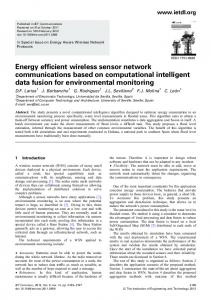
suitable ASN. Obviously such request will go beyond four hops given the earlier attempt by Ac. It should be noted that this process is guaranteed to converge to finding a backup node. The worst case scenario is for a linear topology in which a leaf node will be picked as a backup to a chain of cutvertices. The proof is omitted due to space constraints. After picking its backup, Ac informs its Neighbor1-hop nodes. Unless Bc is actually a 1-hop neighbor of Ac, Bc will then find the shortest path to reach Ac. The recovery will then be conducted either by moving Bc to the location of Ac or triggering a cascaded relocation on the path between Bc and Ac. Basically, if the shortest path between Bc and Ac is through node D and E. Node E will replace Ac, node D will move to where E was and finally Bc will take the position of D. The Pseudo code of the NORAS algorithm is shown in Figure 2. The algorithm is to be executed by the individual nodes without any centralized control. Figure 3 illustrates the operation of NORAS using a detailed example.
• Total traveled distance: reports the total distance that the involved nodes collectively move during the recovery. • Number of relocated nodes: This metric assesses the scope of the recovery process within the network by tracking how many nodes needed to move. • Reduction in Area coverage: This metric measures how NORAS effectively factors in the coverage overlap in designating the backup of a critical node. The following parameters are used to vary the characteristics of the WSN topology in the different simulation experiments and study the implications on the performance of NORAS: Number of Deployed Nodes (N): This parameter affects the node density. A large value of N increases the node density and yields higher network coverage, which boosts the availability of nodes in the vicinity of cut-vertices and enable the designation of close-by nodes as backups. Communication range (Rc): All nodes in the experiments have the same communication range. A large Rc boosts the overall network connectivity and increases the distance that nodes need to move during the recovery. Sensing range (Rs): The coverage range affects the availability of nodes. A large value of Rs will facilitate finding suitable backups in close proximity to critical nodes.
V. PERFORMANCE VALIDATION A. Simulation Environment and Perfroamnce Metrics NORAS is validated through simulation. The simulation environment was developed in Visual C++. In the simulation experiments, strongly-connected WSN topologies of up to 200 sensor nodes are created. The nodes are initially placed based on uniform random distribution in an area of 600m × 1000m and the positions of some nodes are adjusted to connect isolated islands if detected in the formed topology. The following metrics are pursued to assess the performance of NORAS:
The performance of NORAS is compared to DARA [4]. DARA is a distributed algorithm that restores connectivity by replacing the dead node with a suitable neighbor and follows that with a series of cascaded relocation as needed to sustain connectivity throughout the rest of the network. The selection of a replacement depends on the node degree of neighbors and their proximity to the failed node.
(a)
(b)
(c)
(d)
(e)
(f)
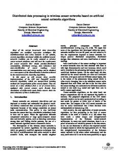
Figure 3: Detailed explanation of how NORAS restores connectivity for the example in Figure 1; (a) the nodes estimate their availability value, as annotated next to the individual nodes, (b) A critical node “35” dies (c) Neighbor1-hop detect the failure (d) Neighbor1-hop spread the failure announcement to notify node 78, which is the designated backup (e) Node 78 reacts and starts the recovery process (f) A cascaded relocation is triggered over the shortest path between node 78 and the failed node in order to restore connectivity.
[Type text]
(a)
(c)
(b)
Figure 5: The performance of NORAS relative too DARA under varying communication range settings (differen nt connectivity conditions). A network size of 100 nodes and Rs are set to 50 meterrs in these experiments.
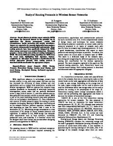
y of the failed critical node availability of nodes in the vicinity becomes high and the spare is picked among the direct neighbors, which makes the recoverry very simple for NORAS. It should be noted that the results of o Figure 4-(b) supports the observations made about Figure 4-(a) above. The limited engagement of nodes decreases the total travel distance, especially for dense networks. Figure 4-(c) reports the effect on o coverage. In general, the loss of a node degrades the field coverage achieved by the WSN. The drop in coverage is more m significant under low density conditions, as is also ap pparent in the graphs for networks of 40 nodes. Since NOR RAS favors a spare whose coverage range is more overlapped d, the effect of node failure on coverage is reduced in compariso on to the case when DARA is employed. As the node density grrows, the recovery becomes mostly influenced by the connecctivity goal and the gap between DARA and NORAS dimin nishes. Figure 5 shows the correspon nding graphs while varying the communication range of nodes. NORAS continues to yield better performance than DARA. Th he performance advantage is in fact consistent and the gap is almost constant for all Rc values. In general, increasing the vaalue of Rc boosts the motion overhead for the recovery since a node will have more n neighbors is larger on the neighbors and the distance between average. Both DARA and NORAS factor in the node degree in selecting a replacement of the faileed node. However, limiting the scope of the relocation to 2-hops gives NORAS a performance edge. In addition, con nsidering coverage overlap
B. Simulation Results We have simulated different WSN topoloogies with some combinations of values of N, Rc and Rs. N iss selected from a set of {40, 60, 80, 100, 150, 200} while Rc andd Rs are varied in the ranges [75, 150] and [25, 150], respeectively. When changing either Rc or Rs, the network size is fixed at 100 nodes. While varying N, Rc and Rs are sett to 100 and 50 meters, respectively. For every topology, NORAS and DARA are applied after failing a randomly selected cut-vertex node. The results of the individual experiments are aaveraged over 30 runs. All results are subjected to 90% connfidence interval analysis and stays within 10% of the sample m mean. Comparison to DARA: Figure 4 shows the disstance that nodes collectively traveled during the recovery for bboth NORAS and DARA. As indicated in the Figure 4-(a), NOR RAS consistently outperforms DARA, especially for sparse nnetworks. As the network size grows, both approaches introduuce little motion overhead and the performance gap diminishees. The reason is that increasing the node density decreases thee distance among nodes and limits the scope of the cascadeed relocation. In addition, for NORAS the potential for coveragge overlap grows with increased node density and thus backupss are easily found among the 1-hop neighbors of critical nodes. Figure 4-(b) shows the average number oof nodes that both NORAS and DARA engage in the recovery. Indeed, NORAS limits the scope of the recovery within the network by involving very few nodes. As the node denssity increases the
(a)
(b)
(c)
Figure 4: Comparing the overhead and coverage pperformance of NORAS to that of DARA for different network k sizes (densities). The graphs are based on Rc=100 and Rs=50 meters.
[Type text]
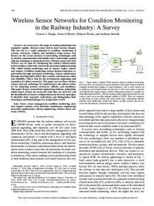
makes NORAS more effective in reducing the impact of the lost node on the field coverage (Figure 5-(c)). Availability Assessment: Figure 6 studies the effect of the availability assessment process on the performance of NORAS. Basically, the performance of a balanced emphasis of coverage and connectivity is compared to that of a coverage-only and node-degree-only assessment of the availability of nodes to serve as spares. Figure 6-(a) shows the simulation results when varying the communication range. As expected, NORAS causes nodes to collectively travel shorter distances than different combinations of coverage (α) and degree( β) used availability assessment recovery. The reason is mainly the consideration of the node-degree which affects the scale of cascaded relocation, i.e., relocating a node with many neighbors impact the connectivity to more nodes. However, the performance advantage over the degree-only backup selection approach is not that obvious. In fact, one would intuitively think that when ignoring coverage the motion overhead will be optimized. The explanation is provided by Figure 5-(a) above. At low communication ranges the performance of NORAS matches that of a degree-only approach. However, the network connectivity grows for large Rc and the total travelled distance increases. NORAS limits that effect through the consideration of coverage overlap. Figure 6-(b) shows the effect on field coverage. As expected, coverage-only availability assessment leads the way in reducing the impact of node failure on coverage by picking
the node with the most overlapped coverage. Not surprisingly, NORAS’ performance lies in between the degree-only and coverage-only approach. VI. CONCLUSION This paper has proposed an effective and efficient recovery scheme for restoring connectivity and limiting the coverage degradation that the failure of a critical node may inflict in WSNs. The main idea of NORAS scheme is to identify critical nodes and assign a backup among the 1-hop and 2-hop neighbors. Upon the detection of the failure, neighbors will call on the service of the backup to replace the critical node. If a backup cannot be picked prior to the failure, NORAS widen the scope of the recovery to ensure that the node loss is tolerated. Backup selection is formulated as a function both node degree and coverage overlap in order to limit the impact of the backup relocation on the network operation and to limit the recovery overhead. The performance of NORAS has been validated through extensive simulation experiments. The simulation results have confirmed the efficiency of NORAS, especially for sparse networks, and its performance advantage over comparable schemes found in the literature. Future extension includes factoring other parameters like task and sensor capabilities in the spare designation process. Acknowledgement: This work is supported by the National Science Foundation, contract # 0000002270. REFERENCES [1]
(a)
(b) Figure 6: The effect of the availability assessment function on NORAS performance under varying Rc and Rs. Results are based on networks of 100 nodes, where Rs = 50 in (a) and Rc is 100 for (b).
I. F. Akyildiz, W. Su, Y. Sankarasubramaniam, and E Cayirci, “Wireless sensor networks: a survey,” Computer Networks, Vol. 38, No. 4, pp. 393-422, March 2002. [2] M. Younis and K. Akkaya, “Strategies and Techniques for Node Placement in Wireless Sensor Networks: A Survey,” The Journal of AdHoc Networks, Vol. 6, No. 4, pp. 621-655, 2008. [3] G. Wang, G. Cao, T. La Porta, and W. Zhang, “Sensor Relocation in Mobile Sensor Networks,” Proc. of the 24th Annual IEEE Conference on Computer Communications (INFOCOM’05), Miami, FL, March 2005. [4] A. Abbasi, M. Younis and K. Akkaya, “Movement-Assisted Connectivity Restoration in Wireless Sensor and Actor Networks,” IEEE Trans. on Parallel and Dist. Sys, 20(9), pp. 1366-1379, September 2009. [5] K. Akkaya, et. Al., “Distributed Recovery from Network Partitioning in Movable Sensor/Actor Networks via Controlled Mobility,” IEEE Transactions on Computers, Vol. 59, No. 2, 2010, pp.258-271. [6] K. Akkaya, et al.,, “Distributed Recovery of Actor Failures in Wireless Sensor and Actor Networks,” Proc. of IEEE Wireless Communications and Networking Conf. (WCNC 2008), Las Vegas, NV, March 2008. [7] N. Bulusu, J. Heidemann, and D. Estrin, “GPS-less Low-cost Outdoor Localization for Very Small Devices,” IEEE Personal Communications, Vol. 7, No. 5, pp. 28–34, Oct. 2000. [8] W Zhang, G. Xue and S. Misra, “Fault-Tolerant Relay Node Placement in Wireless Sensor Networks: Problems and Algorithms”, Proc. of IEEE INFOCOM, Anchorage, Alaska, May 2007. [9] P. Basu and J. Redi, “Movement Control Algorithms for Realization of Fault-Tolerant Ad Hoc Robot Networks,” IEEE Networks, Vol. 18, No. 4, pp. 36-44, August 2004. [10] M. Younis, S. Lee, S. Gupta and K. Fisher, “A Localized Self-healing Algorithm for Networks of Moveable Sensor Nodes,” Proc. of the IEEE Global Telecom. Conf. (Globecom’08), New Orleans, LA, Nov. 2008. [11] N. Tamboli and M. Younis “Coverage-Aware Connectivity Restoration in Mobile Sensor Networks,” Proc. of the IEEE International Conf. on Communications (ICC 2009), Dresden, Germany, June 2009. [12] X. Liu, L. Xiao, A. Kreling, and Y. Liu, “Optimizing Overlay Topology by Reducing Cut Vertices,” Proc. of ACM Workshop on Net. and OS Support for Digital Audio and Video, Newport, RI, May 2006.
[Type text]