Application, a complex Call-Center Solution) how test engineers can now work with the Integrated. Test Environment. Efficiency measurements in the field ...
Efficient Regression Testing of CTI-Systems: Testing a complex Call-Center Solution Andreas Hagerer1, Tiziana Margaria1, Oliver Niese2, Bernhard Steffen2, Georg Brune3 and Hans-Dieter Ide3 1 METAFrame Technologies GmbH, Dortmund, Germany {AHagerer, TMargaria}@METAFrame.de 2 Chair of Programming Systems, University of Dortmund, Germany {Oliver.Niese, Steffen}@cs.uni-dortmund.de 3 Siemens AG, Witten {Georg.Brune, Hans-Dieter.Ide}@wit.siemens.de Abstract. In this paper we show how the workfllow-oriented, library-based test design and execution environment presented in [8] fulfills the promise of enabling efficient integrated system-level tests of complex industrial applications. We exemplify on the basis of a concete case study (Siemens´ HPCO Application, a complex Call-Center Solution) how test engineers can now work with the Integrated Test Environment. Efficiency measurements in the field document an average performance gain in the execution of functional regression tests of factors beyond 30: setting up the test scenario is now the most expensive activity!
1
Introduction
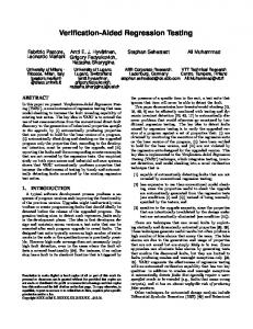
The world of telecommunications has rapidly evolved during the last 15 years, modifying in this process its focus. In 1985 a telephone switch was 'only' used as a telephone switch. Additional components, either hardware or software, were gradually developed to bring additional functionality and flexibility to the traditional switch, e.g. in the initial days voice mail or billing systems. Today not only single functionalities are added at a quick pace, but the switch is mutating its role into the central element of complex heterogeneous and multivendor systems: it is nowadays integrated into whole business solutions, e.g. in the field of hotel solutions, call center and unified messaging applications. Technically, whereas in the earlier days the interaction between the switch and the applications was almost exclusively implemented via proprietary interfaces, today the definition of open standards like e.g. the Computer Supported Telecommunication Applications protocol (CSTA) [1,2], which specifies the command sets and the data structures needed at the application-layer, or TAPI [6],which defines the programming interface for telephony applications, pushes the field towards the development of new, system level applications. The diagram in Figure 1 (left) documents the trend towards a growing product integration in terms of the increase in the number of value-added applications that work in average on or with a switch. As one can see, the integration factor is rapidly increasing since 1995, and the trend points in the direction of even larger value-added product ranges. A parallel but concurring aspect is the increasing number of major switch releases per year (cf. Figure 1 right). This trend is driven mainly by the convergence between the classical telecommunication technology and the modern IP technology, e.g. 'Voice-over-IP': modern switches are themselves complete complex systems, and they experience the accelerating evolution pace of hardware and software in combination! In this rapidly evolving scenario, the need for efficient automated regression testing is evident: whenever a release arises, either of the switch or of (a subset of) the application programs that cooperate with it,singularly or, increasingly often, in collaborative combinations – the correct functioning of the new configurations must be certified again.
Altogether, testing complex telephony solutions is a multidimensional task, which demands automation via adequate system level tool support. The complexity lies in the interaction between the components as well as in the short innovation cycles and the great number of possible combinations between the Private Branch Exchange (PBX) and the value-added applications. Therefore an adequate environment must focus on structuring, efficiency and abstraction. 250
Number of value-added Products
4 200
3,5 3
150 2,5 2 100 1,5 Releases
1
50
0,5 0
Products 1985
0 1990
1995
2000
Number of major Switch Releases per Year
4,5
2003
Year Figure 1: Trends in the development of CTI systems: (left) growing product integration and (right) faster paced switch releases In summary, systems-under-test have become composite (e.g. including Computer Telephony Integrated (CTI) platform aspects), embedded (due to hardware/software codesign practices), reactive, and run on distributed architectures (e.g. client/server architectures). Complex subsystems affect each other in a variety of complex ways, so mastering today's testing scenarios for telephony systems demands for an integrated, open and flexible approach to support the management of the overall test process, i.e. specification of tests, execution of tests and analysis of test results. In [8] we presented an automated testing environment for CTI systems capable of handling their structural complexity: our approach offers a coarse grained testing environment, realized in terms of a componentbased test design on top of a library of elementary but intuitively understandable test case fragments. The relations between the fragments are treated orthogonally, delivering a test design and execution environment enhanced by means of lightweight formal verification methods. Now, one year later, we summarize our practical experiences in the use of this environment at Siemens, where the Integrated Test Environment (ITE) has been used in a production environment. In this paper, we show on the basis of a concrete case study (Siemens´ HPCO Application, a complex Call-Center Solution) how test engineers now work with the ITE. Measurements in the field have exceeded our expectations, documenting an average efficiency improvement in the test execution of functional regressions of complex call-center solutions and of several other CTI applications of factors beyond 30: setting up the test scenario is now the most expensive activity! In the rest of the paper, we first describe in Sect. 2 the concrete industrial application (regression test of a complex Call-Center Solution), then we detail in Sect. 3 the process followed to integrate the Call-Center Solution into the ITE. Sect. 4 presents our field results, concerning in particular the concrete measured speedup of the test execution, and Sect. 5 our conclusions and some perspectives.
2
Regression Test of a Complex Call-Center Solution
A typical example of an integrated CTI platform is a call-center solution, as illustrated in Figure 2, where the switch is connected to the ISDN telephone network or, more generally, to the public switched telephone network (PSTN), and acts as a 'normal' telephone switch to the phones. Additionally, it communicates directly via a LAN or indirectly via an application server with call center client/sever applications that are executed on PCs. Like the phones, these CTI applications are active components: they may stimulate the switch (e.g. initiate calls), and they also react to stimuli sent by the switch (e.g. notify incoming calls). Therefore in a system-level test scenario it is necessary to investigate the interaction between such subsystems. Test Coordinator LAN
Rational Robot TAPI CorNet ISDN Network
Call Center Clients
HUSIM Hipermon
TAPI
CSTA II/III
Call Center Server
Figure 2: Test Setting for a complex Call-Center Solution Even the relatively simple scenario of Figure 2 demonstrates the complexity of CTI platforms from the communication point of view, because there are several (internal) protocols involved. E.g. the telephones communicate via the Corporate Network Protocol1 with the PBX, whereas the PBX communicates via CSTA Phase II/III protocol [1,2] with the application server. On the application server, a TAPI service provider performs a mapping of the CSTA protocol to the TAPI protocol [6], which is the communication protocol between the application server and its clients.
The Integrated Test Environment The Integrated Test Environment (ITE) (cf. [7,8] for a more detailed discussion) is based on an existing general purpose environment for the management of complex workflows, METAFrame Technologies' Agent Building Center (ABC) [11], which contains built in features concerning test coordination and test organization. The Test Coordinator constitutes the test management layer of our environment and includes an application-specific specialization of the ABC for the domain of system level regression testing of telephony systems. To communicate with different test tools a flexible CORBA/RMI-based architecture has been developed. The Test Coordinator executes integrated test cases by controlling several test tools, each managing its own subsystem. The extensibility of the environment by additional test tools is the key of the approach.
1
ECMA and CCITT Q.930/931 oriented D-channel layer 3 protocol for private IPABX.
3
Integration of the Call-Center Solution into the ITE : the Process
To be able to handle regression testing of the call-center solution within the ITE the following steps have to be performed: • Integration of Test Tools • Identification and Implementation of Testblocks • Test case design and execution These steps, which must be taken whenever a new system-under-test is integrated into the ITE, are discussed in detail in the following subsections.
3.1.1 Integrating the Test Tools How to integrate The ITE offers a generic CORBA interface to communicate with the different test tools that comprises the basic methods (e.g. getName, getVersion) that all test tools have to support. Specific features (e.g. input and output commands for testing a special component) can be added at need by extending the interface. The specific methods of the test tools are accessed via test tool-specific basic functionalities (testblocks). The integration process consists of two main activities: 1.
Integration of the interface provided by the test tool into the test coordinator and
2.
Implementation of the interface functionality by the test tool.
If the interface is not implemented in the test tool by the vendor, there are different ways for integration: Plug-in approach: If the test tool supports customisation via loading plugins or libraries, the interface can be integrated by implementing such a plugin including the CORBA object request broker. Separate server process: If a test tool offers remote access via an interface of its own (e.g. COM, DCOM or CORBA) a separate server process can communicate via this interface with the test tool. Then, the special server implements the interface or its derivation and communicates with the test coordinator, i.e. it can be seen as a relay between the test coordinator and the test tool.
What to integrate Two different test tools are used in the call-center scenario: 1.
A proprietary protocol analyser (Hipermon [5]) which is connected to a telephone simulator (Husim) and to the connection between the switch and the application server.
2.
A GUI test tool (Rational Robot [10]), which is used in several instances, i.e. for every considered call center client.
Hipermon/Husim: The required interface to the ITE is implemented in the Hipermon/Husim directly by the vendor. It provides the tester with full access to the whole functionality of a telephone as well as to the underlying protocols, i.e. CorNet and CSTA II/III. The Hipermon is able to decode CorNet/CSTAmessages and to deliver the attached data to the ITE for further processing. Rational Robot: The Rational Robot does not provide a CORBA implementation itself. Here we followed the plug-in approach: we implemented an external library which provides the CORBA functionality and brings the Rational Robot into an interpreter-mode, which allows us to send Robot-Scripts to the Rational Robot for execution. Furthermore it is possible to use generalized scripts which use variables where the concrete values are requested at run time from the ITE.
#Automatically generated, do not edit! SIB startAcdAgent CLS ACDAgent PAR toolName STR 40 "SQA" PAR traceMark STR 40 "" PAR OPT AgentID STR 255 "" BR default
Figure 3: Automatic generation of test building blocks
3.1.2 Identification of suitable Testblocks Several classes of testblocks had to be provided to test the call-center solution: • Testblocks for the user interfaces. The user interface layer concerns the functionality of the features that constitute the user interfaces of the single subsystems, like telephone devices (e.g. hook switch, display and lamps of a telephone set) and software applications (e.g. buttons, check boxes and text fields of an application's graphical user interface). • Testblocks for communication between switch and telephone devices. Devices, both simulated and real, communicate with the switch according to the Corporate Network Protocol (CorNet). • Testblocks for the communication between switch and call center server. The CSTA protocol [1,2] specifies the command sets and the data structures needed for this application-layer. Defining Testblocks for the User Interface Layer Generally, tests of graphical user interfaces are performed by means of 'recording and replaying' tools, which capture events and effects and allow storing them for later execution. The Rational Robot [10] has been made available in the ITE in a flexible way for driving an application's GUI. A testblock is generated automatically for each Robot-script, that is in it turn either recorded or programmed. As shown in Figure 3 (top left), the code of a Robot-script is enriched by special keywords that specify the parameters
of the script. These parameters are essential for the Test Coordinator in order to instruct the Rational Robot during the test execution. This solution enabled the test engineers at Siemens to provide more than 80 different test blocks for a call-center (e.g. logon/logoff of an agent) in a short time by simply recording the actions on the GUI. Defining Testblocks for the CorNet Communication Layer Messages exchanged between switch and device according to the CorNet-protocol • are used to modify display lines, brightness and color of lamps, or ringer mode and ringer pattern • initiate calls, indicate incoming calls, or terminate calls • activate or deactivate specific features of the switch. Such messages are collected by the Hipermon, which decodes them into a format appropriate for a further evaluation within the ITE. In this context, testblocks are needed that either test the current state of a device or simulate the functionality of a device towards the switch. Defining Testblocks for the CSTA Communication Layer CSTA defines a telephony process model for applications and a computing process model for the switch. An implementation of CSTA consists of CSTA-services and the CSTA-protocol. By means of the protocol an application accesses the CSTA-telephony-services from the switch or provides CSTA-computingservices to the switch. Each model consists of a set of objects and rules to change the states of the objects. Examples of telephony objects include • a device object, representing anything that allows users to access telecommunications services. It can be either a physical device (buttons, lines, and stations) or logical devices (a group of devices, an automatic call distribution (ACD) group). A device has attributes, including device type, device identifier and device state that can be monitored and manipulated by an application. In the CTI system of Figure 3, a special CSTA-device (agent) is used. An agent represents the association and the activities of a physical device with an ACD group. An agent, i.e. the physical device, becomes associated with a specific ACD group by a process of logging on. The agent's state describes the current relation of the agent with the ACD group (logged-on, ready to accept calls, busy, working after call). • a call object, describing the logical session among calling and called parties. The call behavior, i.e. its establishment and release, can be observed and manipulated by an application. A call object representing a call session has attributes such as identifier and state and offers operations such as make or clear. One or more devices may be involved in a call in different phases. • a connection object, representing a relationship between a call and a device. It is characterized by attributes such as identifier and state and by operation such as hold or clear. Many CSTA-services, such as hold-call, reconnect-call, or clear-call, are made by operating on connections comprising a call. Basically, CSTA-services consist of a request and a response, both possibly parameterized. A monitor service can be activated to track control and other activities and to receive notification of all changes of the switch. Starting a monitor indicates that an application, be it a component of the system or an external observer, wants to be notified of changes that occur in calls, devices or applications, and device attributes managed by the switch. Examples of changes include arrivals of a call at a device, answering a call, and changing a device by modifying features such as 'forwarding'. Event reports are sent to the monitorrequestor. For the test of CTI-Systems it is necessary to have access to the CSTA-events for validation.
How to Identify and Implement Testblocks To design system-level test cases it is necessary to know which features and functions the system provides, how to operate the system in order to stimulate a feature, and how to determine whether the features work. This information is gathered for each key component of the system and each functional area, resulting in a set of stimulation actions and verification actions that form the basis for the design of test cases in terms of so-called testblocks. These are specified by means of the following three steps: • Classification A testblock name is identified and organized relative to a hierarchical classification scheme. In the call center application, we have classes for each subsystem and each layer.
• •
Parameterization A set of formal parameters is defined to enable a more general usage of a testblock. Connectivity To steer the control flow during test execution, each testblock possesses a set of outgoing branches representing the different possibilities for continuation.
3.1.3 Design and Execution of Testgraphs Once the libraries of testblocks are available, we are ready to design executable test cases. As described in detail in [8] and shown in a very simple case in [9], designing test cases consists of a behavior-oriented graphical combination of testblocks. Icons representing testblocks are graphically stuck together to yield testgraph structures that embody the test behavior in terms of control. A macro technique allows the encapsulation of a section of a testgraph into a new testblock to support a hierarchical design of test cases. Parameters of testblocks that are used in a macro can be specified as parameters of the macro. The design of test cases is controlled by validation techniques that enforce essential technical frame conditions and guarantee the key features of the underlying test purpose, as illustrated in detail in [8]. There we showed how critical consistency requirements including version compatibility and frame conditions for executability are formulated, and how consistency of test cases is fully automatically enforced via model checking and error diagnosis. In the ITE, testgraphs are immediately executable by means of ABC's tracer module. Starting at a specified testblock of a testgraph, the tracer proceeds from testblock to testblock. The actions associated with each testblock are performed, i.e., stimuli and inspection requests are sent to the corresponding system's component, and the responses are received and evaluated. The evaluation results successively determine the selection of the next testblock.
4
Evaluation
To evaluate the economic impact of the ITE introduction, we must first identify the cost factors that pertain to testing CTI systems. Table 1 identifies the macroscopic cost factors that arise along the test process lifecycle together with their frequency of occurrence. Test planning and specification and the definition and setup of test scripts occur only initially, when an experimental scenario (i.e. the testing of a specific CTI system) is set up. The planning and specification phases are not (yet) affected by the ITE. The usual collection or programming of test scripts, that in a manual setting directly constitute the elementary testblocks, is in the ITE supported by a largely automated generation of reusable testblocks that fit with the overall ITE architecture. without ITE
with ITE
frequency
Test planning
manual
manual
once
Test specification
manual
manual
once
Test scripts
manual
manual
once
Test execution
manual
automated (batch)
recurrent
Test protocol
manual
automated
recurrent
Test analysis
manual
(selected cases)
recurrent
Task
Table 1: Regression Test Cost Factors The main focus of the ITE in this first phase is the reduction of costs for the repetitive phases of CTI testing: primarily we addressed test execution, the former bottleneck (cf. Table 2), in combination with the automatic creation of test reports and (in near future) advanced support of the analysis of test results.
Manual
with ITE
speedup factor
Hotel Solutions
10,0
0,5
20
Call Center Solutions
43,0
1,0
43
Analog Voice Mail
23,0
0,5
46
Digital Voice Mail
20,0
0,5
40
Call Charge Computer
19,0
0,5
38
Total
115,0
3,0
ca. 38
System-under-test
Table 2: Test execution effort in hours per regression Table 2 documents the measured improvement of the test execution costs due to the introduction of the ITE. The systems under test considered in each row are composed by the PC client-server application listed in Col. 1 which cooperates with the HICOM switch along the configuration pattern illustrated in Figure 2. The second and third column report the measured effort (in man hours) of one regression cycle for the system under test when performed manually (Col. 2) or with the ITE (Col. 3). The improvement is dramatic: speedup factors of about 30 for each regression cycle execution! Indeed the personnel is now completely freed from manual test execution: the test cases run in batch mode, e.g. at night or while the test engineers work on further test case definitions or on setting up a different test scenario. The automated protocol facility allows them to just look offline at the test cases that ended up with errors or warnings, providing in this case detailed information. The shift towards an automated test execution environment brings additional benefits that go beyond the pure saving of manpower. In particular, the test design activities during the test planning and specification phases have shifted from largely programming to a more conceptual modelling and generation approach. This has effects on the organization and the maintainability of the test suites (there is a high-level model of the test cases), on the documentation of the test runs (if all goes well, few data are stored), on their repeatibility (the configurations etc. are well documented and automatically managed), and on the error diagnosis, where the test graph provides an intuitive guide when looking for causes of misbehaviour. The full automation of test execution is for the moment not yet feasible since some manual steps like system setup and configuration (e.g. physical connection of the components, installation of the software on the machines) are still needed. While in a manual execution setting these steps represented about 20% of the effort for a regression cycle, due to the test execution speedup introduced by the ITE they are now responsible for over 80% of the total effort! We are therefore currently aiming at reducing (or, ideally, automating) the configuration process [4].
5
Conclusion
In this paper we have shown on the basis of a concrete case study (Siemens´ HPCO Application, a complex Call-Center Solution) how test engineers can now work with the Integrated Test Environment in their daily regression testing activities. The workfllow-oriented, library-based test design and execution environment presented in [8] has proved to fulfill the promise of enabling efficient integrated systemlevel tests of complex industrial applications in real life usage. The field experience gathered over the last year has shown that the use of ITE has brought a new dimension of efficiency (with measured speedup factors of above 30 for the test execution phase) for regression testing of large CTI-Systems together with an improved test design methodology and test process organization. A global cost-benefit calculation thus shows that the additional investment for the ITE is well able to pay off in a short period of time, if extensively adopted. The ITE, in fact, dramatically reduces the recurring cost factors almost without impairing the remaining positions that concern the basic effort that still has to be spent along the whole test lifecycle (test planning, manual configuration of the test settings, ...) and the necessary up-front investments (e.g. license fees for test tools, hardware, ...). In fact, we believe that we will be able to also cut down on the required basic effort in near future.
References European Computer Manufactures Association (ECMA): Services for Computer Supported Telecommunications Applications (CSTA) Phase II, ECMA 217/218, 1994. 2 European Computer Manufactures Association (ECMA): Services for Computer Supported Telecommunications Applications (CSTA) Phase III, ECMA 265/2285, 1998. 3 S. Gladstone: Testing Computer Telephony Systems and Networks, Telecom Books, 1996. 4 A. Hagerer, H. Hungar, O. Niese, B. Steffen: Model Generation by Moderated Regular Extrapolation, To appear in Proc. FASE 2002, Int. Conference on Fundamental Approaches to Software Engineering, Grenoble (F), 2002. 5 Herakom GmbH, http://www.herakom.de 6 Microsoft Coorperation: Using TAPI 2.0 and Windows to Create the Next Generation of ComputerTelephony Integration, Whitepaper. 7 O. Niese, B. Steffen, T. Margaria, A. Hagerer, G. Brune, H.-D. Ide: Library-based Design and Consistency Checking of System-level Industrial Test Cases, Proc. FASE 2001, Int. Conference on Fundamental Approaches to Software Engineering. LNCS 2029, Genova (I), Springer Verlag, 2001, pp.233-248. 8 O. Niese, T. Margaria, A. Hagerer, M. Nagelmann, B. Steffen, G. Brune, H.-D. Ide: An Automated Testing Environment for CTI Systems Using Concepts for Specification and Verification of Workflows, Annual Review of Communication, Int. Engineering Consortium (IEC), Chicago (USA), 2000. 9 O. Niese, T. Margaria, A. Hagerer, B. Steffen, G. Brune, H.-D. Ide: Automated Regression Testing of CTI-Systems, Proc. of IEEE European Test Workshop (ETW 2001), Stockholm (S), 2001. 10 Rational, Inc.: The Rational Suite description, http://www.rational.com/products. 11 B. Steffen, T. Margaria: METAFrame in Practice: Intelligent Network Service Design, In Correct System Design -- Issues, Methods and Perspectives, LNCS 1710, Springer Verlag, 1999, pp.390-415. 1