Efficient Routing Mechanisms for Dragonfly Networks Marina Garc´ıa∗ , Enrique Vallejo† , Ram´on Beivide† , Miguel Odriozola§ , and Mateo Valero‡ ∗ IBM Research - Zurich, Switzerland
[email protected] † University of Cantabria, Spain. {enrique.vallejo, ramon.beivide}@unican.es ‡ Universitat Politecnica de Catalunya and BSC, Spain.
[email protected] § GMV, Spain.
[email protected]
Abstract—High-radix hierarchical networks are costeffective topologies for large scale computers. In such networks, routers are organized in supernodes, with local and global interconnections. These networks, known as Dragonflies, outperform traditional topologies such as multi-trees or tori, in cost and scalability. However, depending on the traffic pattern, network congestion can lead to degraded performance. Misrouting (non-minimal routing) can be employed to avoid saturated global or local links. Nevertheless, with the current deadlock avoidance mechanisms used for these networks, supporting misrouting implies routers with a larger number of virtual channels. This exacerbates the buffer memory requirements that constitute one of the main constraints in high-radix switches. In this paper we introduce two novel deadlock-free routing mechanisms for Dragonfly networks that support on-thefly adaptive routing. Using these schemes both global and local misrouting are allowed employing the same number of virtual channels as in previous proposals. Opportunistic Local Misrouting obtains the best performance by providing the highest routing freedom, and relying on a deadlock-free escape path to the destination for every packet. However, it requires Virtual Cut-Through flow-control. By contrast, Restricted Local Misrouting prevents the appearance of cycles thanks to a restriction of the possible routes within supernodes. This makes this mechanism suitable for both Virtual Cut-Through and Wormhole networks. Evaluations show that the proposed deadlock-free routing mechanisms prevent the most frequent pathological issues of Dragonfly networks. As a result, they provide higher performance than previous schemes, while requiring the same area devoted to router buffers. Keywords-Dragonfly Networks; Routing; Deadlock Avoidance;
I. I NTRODUCTION The search for scalable interconnection networks constitutes a key challenge in the design of highly parallel systems such as supercomputers and datacenters. Forthcoming exascale computers will likely employ high radix routers interconnected by means of a direct hierarchical topology. The IBM PERCS [1], the Cray Cascade [2], and the Nvidia Echelon [3] are examples of systems employing such interconnection approach. Dragonfly networks were introduced in [4] as two-layered hierarchical networks. Network nodes (routers) are interconnected by means of a local topology that groups them on supernodes. These supernodes are linked by a global topology that constitutes the whole system. No limitations about the local and global topologies were established for dragonflies in [4], but typically the global topology considered has been a complete graph (all-to-all interconnection) and the local
topology a complete graph (such as in PERCS), or a 2D flattened butterfly (such as in Cascade). In any case, for economical reasons, local links are implemented using electrical wires and global ones with optical links. Although our results can be generalized to systems with any local topology, we restrict our attention to a maximum sized well-balanced network, as defined in [4], based on complete graphs. Such network is defined by an integer parameter h. Supernodes are composed of 2h routers connected by a complete graph K2h . The whole system is composed of 2h2 + 1 supernodes connected by a complete graph K2h2 +1 . Each router has 4h − 1 ports: h injection/ejection ports for computing servers, h global ports for global links, and 2h−1 local ports for local links. The design of an integrated high-degree router for these networks constitutes nowadays an important issue. Aries [2], the most modern interconnection technology from Cray, uses routers of 48 ports, and the Torrent hub employed in PERCS relies on a switch with 56 ports, [5]. Higher degree tiled routers are expected in the future. Virtual channels [6], i.e. multiplexed FIFO buffers per each router port, are commonly used on interconnection networks for several reasons. Avoiding deadlock and reducing head-of-line blocking (HOLB) are among the most important ones. In order to design realistic and affordable high-radix routers, it is compulsory to maintain a reduced number of virtual channels. The amount of memory needed to implement the virtual channel buffers also depends on the link-level flow control mechanism employed. Virtual Cut-Through (VCT) requires space for a whole packet in the next buffer before starting to transmit it, [7]. When transmission starts, the packet can be forwarded on the output port at the same rate at which it is being received in the input port. This implementation has been employed traditionally on HPC system networks, especially when small packets are used and the router degree is low, for example in torus-based topologies such as the BlueGene [8]. This is also the case in Cascade. By contrast, PERCS supports large packets up to 2KB, and employs links of different speeds, what complicates the implementation of VCT. Under Wormhole (WH) flow control [9], packets are subdivided into flits and buffers only need space to hold a few flits. However, WH permits blocking packets along different routers. This can increase network congestion leading to lower performance, and it complicates the deadlock avoidance mechanism by introducing extended dependencies, [10]. The selection
between VCT and WH is a trade-off that depends on several factors as the maximum packet size, links speed, round-trip times and the area and power budgets. Depending on the traffic pattern, Dragonfly topologies can suffer from network congestion due to saturation in local and/or global links. Non-minimal routing, known as misrouting, can prevent this congestion. Global misrouting is used to avoid saturated global links between supernodes, and local misrouting is used to avoid saturated local links within a supernode. A good adaptive routing should select between minimal or non-minimal routing depending on the network load. One of the problems of non-minimal routing is that it allows longer paths. If deadlock avoidance was implemented as in previous proposals, the number of virtual channels required would increase accordingly. This would lead to routers with higher design complexity, area and power consumption. In this paper we study practicable deadlock-free adaptive routing mechanisms, looking for maximum performance on Dragonfly networks. We initially consider a na¨ıve mechanism that requires a large amount of resources, denoted as PAR-6/2. Next, we introduce two novel deadlock-free adaptive routing mechanisms that allow for local and global misrouting without increasing the count of virtual channels with respect to previous proposals. Specifically, the main contributions of this paper are: •
•
•
We introduce Restricted Local Misrouting (RLM), a deadlock-free routing mechanism that relies on a restriction of the allowed routes employed for local misrouting, which prevents cyclic dependencies. Since this routing prevents the appearance of cycles, it works with any flow-control mechanism. We introduce a second adaptive routing mechanism denoted as Opportunistic Local Misrouting (OLM). With OLM cyclic dependencies can appear. However, the design guarantees the existence of an alternative escape path for each packet to reach the final destination, what avoids deadlock. OLM achieves better performance than RLM, but it only works using VCT flow control. We evaluate the proposals by detailed simulation. The results show that both RLM and OLM provide higher performance than previous solutions using the same resources. Additionally, the performance of RLM and OLM is competitive compared to the performance of na¨ıve routing PAR-6/2, which employs twice as many VCs in local ports as RLM and OLM.
The remainder of this paper is organized as follows. In Section II we discuss some related prior work. Section III describes the three deadlock-free routing mechanisms presented in this work. The employed methodology and the obtained performance results are explained in Section IV. Finally, we summarize the conclusions of this paper in Section V.
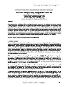
II. P REVIOUS WORK Dragonfly interconnection networks were introduced in [4]. When managing uniform traffic, minimal routing adequately exploits the network resources. Minimal routing requires up to three hops between any pair of routers: l − g − l (local, global, local). An example of a minimal path in a Dragonfly network is shown with a green dotteddashed line in Figure 1. Minimal routing is appropriate when the traffic pattern is uniform, since all links are used evenly. However, depending on the traffic pattern, some links of the network can saturate. As there is a single global link between any pair of supernodes, such link can easily become saturated when multiple nodes from a given supernode send all their traffic to the same destination supernode, [4]. We denote this communication pattern as adversarial-global traffic, ADVG. Similarly, since there is a single local link between any pair of routers in a supernode, saturation can occur in local links when all nodes in a router send their traffic to nodes in the same neighbor router, [11]. We denote this pattern as adversarial-local traffic, ADVL. Global saturation can limit throughput to 1/(2h2 + 1) while local saturation can limit it to 1/h phits/(node · cycle), [12]. To prevent performance degradation generated by adversarial traffic patterns, a load-balancing mechanism can distribute traffic among alternative links using non-minimal routing. Valiant randomized routing is used to avoid the performance degradation generated by ADVG, [13]. Valiant routing sends packets non-minimally towards one intermediate supernode among 2h2 −1 candidates (any supernode except the source and destination ones), and then they are forwarded minimally to the destination. This is denoted as global misrouting, and it balances the use of global links, generating paths up to 5 hops long: l −g −l −g −l. Figure 1 shows with an orange fine-dashed line an example of a path with global misrouting. Interestingly, a pathological case of local link saturation also occurs when using global misrouting under ADVG traffic, [12], and can limit throughput to 1/h. Similarly to global misrouting, local misrouting can be used within a supernode to avoid a saturated local links. Adaptive routing balances traffic among minimal and non-minimal routes depending on the traffic pattern. A set of indirect adaptive routing mechanisms for Dragonfly interconnection networks were proposed in [14]. Among the proposals presented in that paper, Piggybacking (PB), which broadcasts status information of the global links to all adjacent routers inside supernodes, was selected by the authors as the solution with the best cost/performance ratio. For each packet, Piggybacking employs source routing, selecting between minimal or Valiant routing at injection time. Similar approaches are taken in CRT and UGAL, also in [14]. Progressive Adaptive Routing (PAR, [14]), introduces the idea of in-transit adaptive routing when changing traffic conditions are found at the source supernode. PAR chooses between minimal and Valiant (global misrouting) at injection time. However, after a first minimal local hop, it can also revert to Valiant routing if
Valiant
M in im al
Destination router
Adaptive
Source router
Figure 1: Minmal, Valiant and Adaptive routing with local misrouting routes examples in a Dragonfly interconnection network.
the minimal global link happens to be saturated. If this happens, the longest route with PAR will have 6 hops: l − l − g − l − g − l. It is known that deadlock avoidance mechanisms can be costly and can adversely impact performance. The cost/performance merits of deadlock avoidance solutions depend, among other factors, on the routing and flow control mechanisms. Previous deadlock avoidance techniques for dragonfly networks, [4], [1], rely on a distance-based method proposed by G¨unther in [15]. This method uses as many virtual channels per link (or router port) as hops in the longest path allowed in the network. A possible implementation always injects packets at the first virtual channel, let us say the one with index 1, and for each hop the index of the next used virtual channel is incremented in one unit. The rationale behind this method can be easily grasped: the last VC never blocks because packets are about to be consumed; any other previous VC never blocks because it depends on the following one, in which packets either advance to a higher VC in the next hop or are consumed in the current router. In Dragonflies using this deadlock avoidance technique, any path must use an ascending sequence of virtual channels. Considering the longest route with global misrouting (l−g−l−g−l), these channels would be V C1 , V C2 , V C3 , V C4 , V C5 . Notwithstanding, not all router ports need to physically implement these five virtual channels. In the longest path, the hops in positions 1, 3 and 5 correspond to local links; the corresponding VCs will be implemented as lV C1 , lV C2 and lV C3 FIFOs on local ports. The hops in positions 2 and 4 correspond to global links and they will be implemented as gV C1 and gV C2 FIFOs on global ports. Consequently, the longest ascending VC sequence will be lV C1 −gV C1 − lV C2 −gV C2 −lV C3 . Several implementations using 3 VCs in local ports and 2 VCs in global ports were presented in [4], [14], [1]. We will refer to this typical configuration supporting only global misrouting as 3/2 VCs. Similarly,
PAR requires 4 virtual channels in local links and 2 in global ones: lV C1 − lV C2 − gV C1 − lV C3 − gV C2 − lV C4 . That is, it needs an extra virtual channel for local ports to avoid deadlock. OFAR, introduced in [12], is the only previous proposal that supports adaptive local and global misrouting. This generates paths up to 8 hops: 2 of them global and 6 local. Figure 1 shows with a red dashed line an example of a path resulting from that adaptive routing mechanism. For deadlock avoidance, OFAR relies on an escape deadlock-free subnetwork, [16], based on a Hamiltonian physical ring regulated by bubble flow-control, [17], [18]. Although this mechanism can be implemented without virtual channels, the poor capacity of the escape subnetwork can become a system bottleneck leading to a significant performance drop in congested scenarios. The use of additional congestion management mechanisms to mitigate this problem has been studied in [19], but still very long paths are theoretically possible. In addition, this mechanism does not work with Wormhole flow-control, and the hops on the escape subnetwork can significantly increase the latency of some packets, which makes alternative mechanisms appealing. III. D EADLOCK - FREE ROUTING P ROPOSALS In this Section we introduce three different deadlockfree adaptive routing mechanisms for Dragonfly networks. The two first schemes can deal with both WH and VCT flow control, while the third one only works under VCT. At least 3 VCs in local ports and 2 in global ports (3/2) are required in previous proposals to support global misrouting. Since the impact on performance of global links congestion is very high, 3/2 VCs will be the baseline in terms of cost for our proposals. All the deadlock-free routing mechanisms introduced below support in-transit adaptive routing in which packets can circumvent congested links via local and global misrouting. Each router tries to forward traffic minimally. Nevertheless, if minimal routes are congested, packets will be misrouted off their shorter paths. The longest allowed route includes one global misrouting and one local misrouting per each visited supernode (source, intermediate and destination supernodes), generating routes of, at most, 8 hops: l − l − g − l − l − g − l − l. Shorter paths are also possible. Their lengths, between 7 and 1, depend on the relative positions of the injector and consumer and on the number of misroutings taken by the packet. Adaptivity is exploited on-the-fly, the routing decision can be revisited on each hop. Routing chooses between the minimal output and one of the possible non-minimal outputs using a misrouting trigger based on the credits count of the output ports. If the minimal output is not available, a non-minimal output is randomly chosen among those with an occupancy lower than a given threshold. This threshold is a percentage of the occupancy of the minimal queue. Global misrouting will be performed, if necessary, in the source supernode, either at the source router or after the first minimal hop as in PAR, [14]. In addition,
local misrouting is allowed at both the intermediate and the destination supernodes as in OFAR, [12]. Next, the discussion of each proposal will focus on how to support local misrouting inside supernodes without jeopardizing whole network-wide deadlock freedom. A. Na¨ıve: PAR-6/2 This basic mechanism is an extension of the original PAR in [14], to which we have added support for local misrouting in the intermediate and destination supernodes. Deadlock is avoided using the original mechanism from [15]. Using as many virtual channels as hops in the longest path and traversing them in ascending order, deadlock freedom is guaranteed. In this case, as local links could be used up to six times (one local misrouting per supernode), six virtual channels are needed on local links to guarantee ascending order. Hence, a packet traveling through one of these longest routes will use links and virtual channels in the following order: lV C1 − lV C2 − gV C1 − lV C3 − lV C4 − gV C2 − lV C5 − lV C6 . This simplistic deadlock-avoidance mechanism works with WH and VCT flow control, without imposing any routing restriction. However, the large amount of virtual channels needed would increase the cost and complexity of the router, what could make it impracticable. Hence, this proposal will only be considered as a reference. B. Restricted Local Misrouting (RLM) We introduce next the Restricted Local Misrouting, a deadlock-free adaptive routing mechanism that requires 3/2 VCs. This mechanism can be used with VCT and WH flow control. It is based on avoiding cyclic dependencies inside supernodes by restricting routing freedom, based on similar ideas as the Turn Model, [20]. In that work, the authors show that prohibiting just enough turns to break all of the possible cycles in a network, produces routing algorithms that are deadlock free. In the Dragonfly configuration that we study in this work, routers within a supernode are connected by means of a complete graph. When local misrouting is allowed, each packet can traverse, at most, two local links per supernode. The Restricted Local Misrouting (RLM) mechanism allows certain 2-hop routes from every source to destination node so that cycles are never generated. The RLM can be also applied to other topologies for the local network of a Dragonfly. There are different methods to select the set of length2 paths that should be forbidden. Each method will determine the number of available routes for each pair of source-destination routers. In order to accept the traffic from the h computing nodes attached to each router, at least h disjoint paths are required between each pair of nodes (h − 1, plus the 1-hop minimal path). However, a simplistic mechanism can lead to an unbalanced number of non-minimal paths for different pairs of routers. We will examine next how a simple scheme, denoted as signonly does not guarantee h − 1 non-minimal paths between any pair of routers, and then we will introduce a more
7
0
X
6
1
5
2 4
3
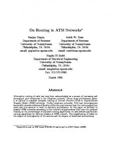
Figure 2: Intra-group routers connections in a Dragonfly network. Some examples of forbidden and allowed hop combinations with the route restriction technique.
elaborated one which solves this problem, denoted paritysign. We will use a small Dragonfly with h = 4 as an example. Figure 2 shows the interconnection in a complete graph of the 2h = 8 routers composing a supernode in a system of this scale. The simple sign-only approach relies on forbidding a given turn. links (or hops) are classified according to their directions. We will refer to a hop (or link) as positive (+) (respectively, negative −) if it is a hop from a router with index i to a router j where i < j (respectively i > j). For example, a hop from router 3 to router 6 is positive. Local misroutings inside supernodes could be made of paths (+, +), (−, −), (+, −) and (−, +). We consider as turns those hop combinations that change direction from positive to negative or vice versa. The sign-only approach avoids deadlock by forbidding one of those turns, for example hop combinations (+, −) starting with a positive hop and ending with a negative one. An example of a set of routes that would cause cyclic dependencies is shown in Figure 2. It shows 3 different hop combinations: • Combination 1: From node 0 to 1, through 5; (+, −). • Combination 2: From node 5 to 0, through 1; (−, −). • Combination 3: From node 1 to 5, through 0; (−, +). In this example, Hop combination 1, from node 0 to node 1, through node 5, would be forbidden by the signonly mechanism and no cyclic dependencies would appear. However, there would not be any non-minimal allowed route from node 0 to node 1 because they all need to be (+, −). The number of possible routes of two hops thus varies depending on the routers indices. Some pairs of routers would have just the minimal route connecting them (for example, nodes 0 and 1), while others could have up to 2h−1 routes (for example, nodes 0 and 7). This generates an unbalanced use of the links in the local networks and, as a result, a reduced performance. For space restrictions, we omit the results of this model.
The parity-sign mechanism is our proposed alternative that overcomes this unbalance problem. This mechanism considers four types of hops in the local network depend not only on their direction (sign) but also on their parity. The links (hops) that connect two routers with different parity will be denoted as odd links (hops), represented by black solid lines in Figure 2. For example, the link connecting router 5 with router 2. Analogously, even links (hops) connect two routers with the same parity, represented by black dashed lines in Figure 2. For example, the link connecting router 1 with router 7. Considering parity and sign, there are four types of links. Table I shows the 16 possible 2-hop combinations. Sequences of consecutive pairs of hops are allowed, only if the second pair starts with the same kind of link as the the previous pair ended. However, the key idea of the parity-sign mechanism is that in any (possibly long) sequence, the last link is never the same as the initial one. This can be guaranteed by forbidding certain 2-hop paths depending on their link types. To do this, each pair of link types in Table I needs to be marked as Allowed or Not allowed, with the following criteria. Initially, the column Allowed of the Table is blank. First, all hop combinations with both hops of the same kind are set as Allowed, because they can never generate cyclic dependencies: [odd−, odd−], [even+, even+], [odd+, odd+] and [even−, even−]. Next, one link type is selected. The pairs that start with this link type and are still blank, are marked as Allowed. To prevent cycles and guarantee deadlock freedom, all the remaining pairs which end in this link type and are still blank, are marked as Not allowed. This is repeated with the other three link types. Depending on the order of link types employed, the solution will be different. The solution in Table I is obtained using the order (1) odd−, (2) even+, (3) odd+ and (4) even−. Finally, in order to obtain the set of allowed intermediate nodes for any pair of routers i and j, all the remaining routers k are considered: if the hop combination type(i − k), type(k − j) is Allowed, then k is a valid intermediate node from i to j. This calculation can be done in advance and saved in a misrouting table in node i, or verified at the time of routing a packet in i. A set of routes generated with this mechanism is deadlockfree by construction, since cycles can not appear if the first and last links are different. The number of routes of two hops between any pair of nodes allowed by Table I is, at least, h − 1. Considering also the minimal route of just one hop, this accounts for the required h routes. In the example of Figure 2, hop combination 2 (from node 5 to node 0, through node 1), should be forbidden as it is of type [even−, odd−]. This hop combination is represented by a red dashed line marked as forbidden with a cross. However, a packet could reach node 0 from node 5 going through nodes 2 and 4 ([odd−, odd−]) and 6 ([odd+, odd−]). That means, there are h − 1 = 3 possible routes of two hops between nodes 5 and 0, plus one direct route. In a Dragonfly network, if a packet is globally misrouted
Hop combination odd− odd− odd− odd− even+ even+ even+ even+ odd+ odd+ odd+ odd+ even− even− even− even−
even+ (1) even− (1) odd+ (1) odd− even+ even− (2) odd+ (2) odd− even+ even− (3) odd+ odd− even+ even− odd+ odd−
Allowed
Reason
YES YES YES YES YES YES YES NO NO YES YES NO NO YES NO NO
(1) (2)
(1) (2) (3) (1)
Table I: Possible hop combinations for local misrouting within supernodes, including which combinations are allowed or not and why with the parity-sign technique.
it traverses 3 different supernodes. Using this technique, the two-hop routes within supernodes are restricted and no cyclic dependencies will appear. Hence, packets can make both hops in the same supernode using the same VC. As a result, 3 virtual channels in local queues and 2 in global ones are enough to avoid deadlock. Longest paths will use the following sequence of links and VCs: lV C1 −lV C1 −gV C1 −lV C2 −lV C2 −gV C2 −lV C3 −lV C3 . As it can be seen, the ascending order in the use of VCs has been violated; a packet can traverse 2 local channels in the same supernode using the same VC. However, cyclic dependencies are avoided by restricting those routes that use the same local VC inside supernodes. C. Opportunistic Local Misrouting (OLM) We propose next an alternative deadlock-free routing that uses 3/2 VCs, but has the same routing freedom as PAR-6/2. This mechanism, denoted as Opportunistic Local Misrouting (OLM), requires the use of VCT flow control. The idea behind this mechanism is that packets can freely circulate on a network, even creating cyclic dependencies, as long as they always have a deadlockfree route to their destination that allows breaking such dependency. Typically, this deadlock-free route is denoted as escape path. Rather than relying on a deadlock-free escape subnetwork like the ring proposed in [12], which restricts the escape routes and is prone to congestion, OLM employs escape paths in the Dragonfly network preserving an increasing VC order. The diameter of a twolevel hierarchical network based on complete graphs is 3, so any packet in any node of the network can reach its destination using only three hops: l − g − l. In a simple implementation these hops could employ the last sub-set of VCs: lV C2 − gV C2 − lV C3 . Then, lower VCs lV C1 and gV C1 could be employed to adaptively route traffic with local and global misrouting, and if a packet could not advance towards a certain output port, it could always revert to its escape path.
lVC3
D
D 1
gVC2 lVC2
4
2
gVC1
D 6
5
3
1
3
3
lVC1
1
7
5
1
2
S
S
S
a)
b)
c)
2
i
Router i
4 Hop with increasing order in VCs Hop with lower or equal order in VCs
Figure 3: Examples of in-transit adaptive routes and the use of virtual channels.
In order to balance traffic across the different virtual channels and to reduce the likelihood of cyclic dependencies that decrease throughput, our implementation of OLM is an evolution from the previous basic idea. With 3/2 VCs, packets can follow both minimal and Valiant deadlock-free paths using an increasing order of VCs. However, local misrouting hops, if allowed, cannot follow such order. When, instead of a minimal hop, a local misrouting is done, the distance of a packet to its destination node remains the same instead of decreasing. To guarantee that packets can always reach their destination nodes through an escape route with an ascending order of VCs, the VC employed for local misrouting needs to be lower or equal to the current one. Therefore, a packet can be opportunistically misrouted inside supernodes if it finds enough space to completely store it in a local VC of the selected neighbor with equal or lower index than the previously used one. Thus, packets always have the possibility of reaching their destination nodes following a route that uses the virtual channels in the strict increasing order, what assures deadlock freedom in the network. In this manner, our implementation opportunistically employs both minimal and Valiant routes as safe escape paths. Figure 3 shows three different paths between a source router S and a destination router D, with the order in which virtual channels are visited to avoid deadlock. •
•
•
Route a) Represents a case when a packet is globally misrouted to an intermediate supernode at injection time. That is, gV C1 – lV C2 – gV C2 – lV C3 . Route b) Represents a case when a packet is globally misrouted to an intermediate supernode after a first minimal hop in the source supernode. That is, lV C1 – lV C1 – gV C1 – lV C2 – gV C2 – lV C3 . Route c) Represents a case when there is a global misrouting after a first minimal hop in the source supernode and two local misroutings, one in the intermediate and the other in the destination supernodes. That is, lV C1 – lV C1 – gV C1 – lV C1 – lV C2 – gV C2 – lV C2 – lV C3 .
Route a) employs VCs in the correct ascending order without exploiting local misrouting. Routes b) and c) use global misrouting after a first minimal hop in the source supernode, as in Progressive Adaptive Routing [14]. This first local detour is possible because there was space for the whole packet at lV C1 in router 2. In this way, the
packet can continue to destination still having lV C2 and lV C3 to be used in ascending order at intermediate and destination supernodes. Route c) performs as well local misroutings at intermediate and destination supernodes. Routers 3, 4 and 5 correspond to the intermediate supernode and routers 6, 7 and D correspond to the destination one. The local misrouting (3, 4) has been possible because router 4 had space for the packet in its lV C1 queue; lV C2 and lV C3 remain safe to be used in the remainder of the path. Finally, local misrouting (6, 7) has been possible because router 7 had space for the packet in its lV C2 queue; lV C3 remains safe to be used in the remainder of the path. This last local misrouting could be also done over lV C1 . IV. M ETHODOLOGY AND P ERFORMANCE R ESULTS This section studies the performance of the three deadlock-free routing mechanisms presented above: PAR6/2, Restricted Local Misrouting (RLM) and Opportunistic Local Misrouting (OLM). For each of these mechanism, we employ a misrouting threshold chosen sweeping the possible values. The threshold is selected as a tradeoff between performance under uniform and adversarial traffic. This process is detailed in Subsection IV-C. We will compare PAR-6/2, OLM and RLM performance results to those obtained with minimal, Valiant and Piggybacking (PB) routing. Minimal routing is the baseline for uniform traffic and Valiant for adversarial-global (ADVG) traffic patterns, while PB is the adaptive routing with the best overall results among those presented in previous works. To carry out this evaluation, we have implemented all the previously described mechanisms on an in-house developed single-cycle simulator that models FIFO inputbuffered routers with VCT or WH flow-control. We model a maximum size Dragonfly with routers of 31 ports (h = 8) and complete graphs for the inter and intra-group interconnects. This network connects 16,512 computing servers using 2,064 routers organized in 129 supernodes of 16 routers. The default network latencies are 10 cycles for local links and 100 cycles for global ones. The size of each local FIFO is 32 phits, and 256 phits for each global FIFO, enough for the flow control requirements dictated by round-trip latencies. We use 2 VCs per global link and 3 per local link and injection queues, except for PAR-6/2, for which we use 6 VCs in the local ports. The traffic to evaluate performance is synthetic. Source nodes generate packets according to a Bernoulli process. The injection probability is set in phits/(node·cycle). We employ uniform (UN) and adversarial (ADVG and ADVL) traffic patterns. With UN, each node in the network sends traffic to destination nodes randomly chosen among all the rest of nodes in the network. We denote ADV G + N the adversarial global traffic in which all nodes in supernode i send their packets to random nodes in supernode i+N (mod(2h2 +1)). Similarly, we denote as ADV L+N the adversarial local traffic in which all nodes in router i send their packets to another node in router i+N (mod2h) of the same supernode. In the ADV G traffic, two patterns
with different severity are examined, ADV G + 1 and ADV G + 8. With h = 8, ADV G + 8 requires both local and global misrouting to obtain the maximum performance because of the pathological saturation of a local link in the intermediate supernode, as studied in [12]. We evaluate next the behavior of the different adaptive routing mechanisms. We will consider first VCT simulations and then the WH flow control case. A. Virtual Cut-Through We evaluate now the performance obtained with each mechanism with Virtual Cut-Through (VCT) flow-control considering packets of 8 phits. This scenario of small packets managed under VCT flow control tries to resemble, in some way, the conditions of a system similar to the Cray Cascade, which has a payload per packet of 64 bytes, [21]. First, we obtain throughput and latency values for three different traffic patterns in steady state: Uniform (UN), adversarial+1 (ADVG+1) and adversarial+8 (ADVG+h, since h = 8). Figure 4 depicts the latency results, while the throughput results are shown in Figure 5. Figure 5a shows that under uniform traffic (UN) the highest throughput is obtained with PAR-6/2. However, the throughput reached by the Opportunistic Local Misrouting (OLM) is very similar, and Restricted Local Misrouting (RLM) is also very close. It can also be observed in Figure 5a that PAR6/2, OLM and RLM, get higher throughput than Minimal routing. Although Uniform random traffic tends to balance load in the network, sometimes several packets compete for the same minimal link. These situations can be avoided misrouting packets through non-minimal links. Contrary to Minimal routing, the three on-the-fly adaptive routing mechanisms allow misrouting, giving as a result a higher throughput. However, those misroutings increase average path length and, consequently, average packet latency. This can be confirmed in Figure 4a. When comparing the three routing mechanisms proposed in this work, RLM provides the best latency results. As it can be observed in Figures 5a and 4a, this three mechanisms present better latency and throughput values than PB. This is because PB is slower sensing congestion. Moreover, with PB, when a packet is misrouted, it has to be sent through a Valiant route, increasing average latency values. Figure 5b shows that the in-transit adaptive routing mechanisms reach higher throughput than Valiant and PB under ADVG+1. In Figure 4b, it can be seen how their latencies also saturate at higher offered load values. In this case, the RLM presents slightly better throughput. However, due to the path restriction, the latency values at low offered loads for RLM are higher. Figure 4c shows how PB and Valiant routing saturate at very low traffic loads with ADV G + h. This is because these routings do not allow for local misrouting. PAR-6/2 and OLM saturate when the offered load is approximately 0.35 and RLM around 0.3. It can be observed in in Figure 5c that RLM obtains lower throughput than PAR6/2 and OLM. This is due to its lower number of allowed non-minimal paths. The highest throughput obtained by
Valiant and PB is lower than 0.125. The reason for this is that non of them allows local misrouting. As explained before, local misrouting is necessary when the traffic is ADVG+h, due to the pathological saturation of local links in the intermediate supernode that limits throughput to 1/h = 1/8 = 0.125. We simulate next a situation that combines adversarial local and adversarial global traffic. With this traffic pattern a certain percentage, p, of the traffic sent by each node will be global (ADVG+8), and the reminder (1 − p) will be local (ADVL+1). Note that both traffics require local misrouting for maximum performance. In this experiment, the offered load is always 1 phit/(node·cycle). Figure 6a shows the maximum throughput reached as the percentage of global traffic (ADVG+8) varies. As it can be observed, all the proposals that support local misrouting obtain higher throughput than PB. With h = 8 and 0% of the traffic global (all the traffic is local (ADVL+1)), the throughput is bounded by 1/h = 12.5% if no misrouting is allowed. PB routing does not allow for local misrouting and a realistic implementation would likely prevent global misrouting when traffic is internal to a supernode, leading to the maximum of 0.125 phits/(node · cycle). However, our implementation can send local traffic through a Valiant path (global misrouting, back and forth to a random supernode) to increase performance. That is why, as shown in Figure 6a its throughput approaches 0.5 phits/(node · cycle) when all the traffic is local. RLM, PAR-6/2 and OLM, that permit local misrouting, obtain a throughput of 0.61, 0.79 and 0.79 phits/(node · cycle) respectively. The throughput values of the 4 studied mechanisms decrease as the percentage of global traffic increases. The results with a 100% of global traffic fit with those in Figure 5c for an offered load of 1 phit/(node · cycle). On average, the mechanism with the highest throughput is OLM, even higher than for PAR-6/2, which needs 6 VCs per local channel instead of 3. Figure 6b shows results for a bursts consumption experiment. Each node in the network sends 1000 packets following the traffic pattern ADVG+8/ADVL+1. The simulator generates such traffic and reports the cycles required for the network to consume all the packets. We vary the percentage of global traffic on each simulation. The consumption times of our adaptive routing mechanisms are always significantly lower than for PB. In general, OLM presents the best result. On average, OLM burst consumption time is a 36% of the consumption time of PB. The result for RLM is slightly worse than the result for OLM. However, its burst consumption time is very competitive compared to PB. On average, RLM needs just a 42.5% of the time needed by PB to consume all the traffic. B. Wormhole In this Subsection we evaluate the performance obtained by PAR-6/2, RLM, minimal, Valiant and PB under Wormhole (WH) considering packets of 80 phits divided into 8 flits of 10 phits. We do not evaluate OLM here
Minimal PiggyBacking
PAR-6/2 OLM RLM 200
PAR-6/2 OLM RLM
270
190
160 150 140 130
Average latency (cycles)
Average latency (cycles)
170
250 240 230 220 210
120 110
0
0.1
0.2
0.3
0.4
0.5
200
0.6
0
0.1
Offered load (phits/(node*cycle))
0.2
0.3
0.4
280 260 240 220 200
0.5
Offered load (phits/(node*cycle))
(a) Latency UN/VCT.
Valiant PiggyBacking
300
260
180
Average latency (cycles)
Valiant PiggyBacking
PAR-6/2 OLM RLM
0 0.05 0.1 0.15 0.2 0.25 0.3 0.35 0.4 Offered load (phits/(node*cycle))
(b) Latency ADVG+1/VCT.
(c) Latency ADVG+h/VCT.
Figure 4: Latency under uniform (UN) and adversarial traffic (ADVG+1 and ADVG+h) with VCT flow-control.
Minimal PiggyBacking
PAR-6/2 OLM RLM
PAR-6/2 OLM RLM
0.5
0.6 0.55 0.5 0.45 0.4
0.4
0.5
0.6
0.7
0.8
0.9
0.4 0.35 0.3 0.25 0.2 0.15 0.1 0.05 0
1
0
0.2
Offered load (phits/(node*cycle))
0.4
0.6
0.8
Offered load (phits/(node*cycle))
(a) Throughput UN/VCT.
Valiant PiggyBacking
0.5
0.45
Accepted load (phits/(node*cycle))
Accepted load (phits/(node*cycle))
Accepted load (phits/(node*cycle))
0.7 0.65
0.35
Valiant PiggyBacking
PAR-6/2 OLM RLM
(b) Throughput ADVG+1/VCT.
1
0.4 0.3 0.2 0.1 0
0 0.1 0.2 0.3 0.4 0.5 0.6 0.7 0.8 0.9 1 Offered load (phits/(node*cycle))
(c) Throughput ADVG+h/VCT.
Figure 5: Throughput under uniform (UN) and adversarial traffic (ADVG+1 and ADVG+h) with VCT flow-control.
RLM PiggyBacking
PAR-6/2 OLM
Burst Consumption Time (1000 Cycles)
Accepted Load (phits/(node*cycle))
1
0.8
0.6
0.4
0.2
0
0
20
40
60
80
Global Traffic Percentage (%)
(a) Throughput.
RLM PiggyBacking
PAR-6/2 OLM
100
80 70 60 50 40 30 20 10 0
0
20
40
60
80
100
Global Traffic Percentage (%)
(b) Burst consumtion time.
Figure 6: Throughput and burst consumption time under ADVG+8/ADVL+1 traffic, VCT.
as it requires te use of VCT flow-control. This scenario of larger packets managed under WH flow control tries to resemble, in some way, the environment of a system similar to the IBM PERCS, [21]. As in the previous Subsection, we present throughput and latency values under 3 different global traffic patterns: Uniform (UN), adversarial +1 (ADVG+1) and adversarial+8 (ADVG+h). The latency and throughput results are shown in Figure 7 and Figure 8. The base
latency is significantly higher than in the previous Subsection because of the transmission time of the larger packets employed in this experiment. Additionally, with WH latencies increase faster with the offered load. This behavior has been studied before, for example in [22]. Figure 7a shows that under uniform traffic the latency of RLM is very close to the one of PAR-6/2, both of them lower than the latency of PB and very close to the result of minimal routing. Figure 8a shows that the highest throughput is obtained when PAR-6/2 is employed. As explained in Subsection IV-A, one reason for the better throughput obtained by PAR-6/2 is the possibility of in-transit misrouting. Additionally, PAR-6/2 uses 6 VCs for local ports instead of 3. This higher number of VCs mitigates the effects of Head-of-Line Blocking and improves performance. Finally, the throughput of RLM is very close to the one of PB, but slightly higher. In Figure 7b, RLM has lower latencies than PB for all the load range under ADVG+1. Interestingly, RLM latencies are quite close to the ones obtained by PAR6/2. Figure 8b shows that RLM and PAR-6/2 reach higher throughput than PB, being PAR-6/2 the mechanism that obtains the highest. Very similar results can be observed in Figures 7c and 8c, which show the throughput and latency results when the traffic is ADVG+h. In this case the
Minimal PiggyBacking
Average latency (cycles)
400
Average latency (cycles)
Valiant PiggyBacking
PAR-6/2 RLM
350
300
250
600
600
550
550
500 450 400 350
200
0
300
0.05 0.1 0.15 0.2 0.25 0.3 0.35 0.4
500 450 400 350
0
Offered load (phits/(node*cycle))
0.1
0.2
0.3
0.4
300
0.5
0
Offered load (phits/(node*cycle))
(a) Latency UN/WH.
Valiant PiggyBacking
PAR-6/2 RLM
Average latency (cycles)
PAR-6/2 RLM
0.05 0.1 0.15 0.2 0.25 0.3 0.35 0.4 Offered load (phits/(node*cycle))
(b) Latency ADVG+1/WH.
(c) Latency ADVG+h/WH.
Figure 7: Latency under uniform (UN) and adversarial traffic (ADVG+1 and ADVG+h) with WH flow-control.
Minimal PiggyBacking
0.4 0.3 0.2 0.1
0
0.2
0.4
0.6
0.8
Offered load (phits/(node*cycle))
(a) Throughput UN/WH.
1
0.5 0.4 0.3 0.2 0.1 0
0
0.2
0.4
0.6
Valiant PiggyBacking
PAR-6/2 RLM
Accepted load (phits/(node*cycle))
0.5
0
Valiant PiggyBacking
PAR-6/2 RLM
Accepted load (phits/(node*cycle))
Accepted load (phits/(node*cycle))
PAR-6/2 RLM
0.8
0.5 0.4 0.3 0.2 0.1 0
1
0
Offered load (phits/(node*cycle))
0.2
0.4
0.6
0.8
1
Offered load (phits/(node*cycle))
(b) Throughput ADVG+1/WH.
(c) Throughput ADVG+h/WH.
Figure 8: Throughput under uniform (UN) and adversarial traffic (ADVG+1 and ADVG+h) with WH flow-control.
PiggyBacking
PAR-6/2 RLM
Burst Consumption Time (1000 Cycles)
0.6 0.5 0.4 0.3 0.2 0.1 0
0
20
40
60
80
Global Traffic Percentage (%)
(a) Throughput.
PiggyBacking
PAR-6/2 RLM
0.7 Accepted Load (phits/(node*cycle))
difference in the maximum throughput reached by Valiant or PB and the in-transit adaptive routing mechanisms is much higher. Again, this is due to the fact that Valiant and PB do not allow for local misrouting. Next, we study the maximum throughput with the adversarial local and adversarial global traffic pattern explained in Subsection IV-A. Throughput results are shown in Figure 9a. When all the traffic is local PB obtains a maximum throughput of 0.39 phits/(node · cycle), while PAR-6/2 and RLM reach a maximum throughput of 0.59 and 0.54 phits/(node · cycle) respectively. For the three mechanisms the maximum throughput decreases while the percentage of global traffic increases. When all the traffic is global, the throughput for PB is close to 0.125 phits/(node · cycle), for PAR-6/2 it is 0.39 phits/(node · cycle), and for RLM 0.34 phits/(node · cycle). As in the VCT experiment, the low throughput results of PB are due to the lack of local misrouting. Overall, PAR-6/2 is the mechanism that reaches the highest throughput. However, the throughput obtained by RLM, which needs half the local VCs needed for PAR-6/2, is also very competitive. Figure 9b shows results of a bursts consumption experiment. Each node in the network sends 89 packets of length 80 phits divided into 8 flits of 10 phits and he traffic pattern followed is ADVG+8/ADVL+1. In this experiment the number of packets sent by each node is 89 instead of 1000
100
80 70 60 50 40 30 20 10 0
0
20
40
60
80
100
Global Traffic Percentage (%)
(b) Burst consumption time.
Figure 9: Throughput and burst consumption time under ADVG+8/ADVL+1 traffic, WH.
so that the total payload sent is as similar as possible to the experiment in Subsection IV-A. The burst consumption times for PAR-6/2 and RLM are significantly lower than for PB. In general, PAR-6/2 shows the best consumption times, just slightly better than RLM. On average, the burst consumption time for RLM is a 43% of the time needed by PB.
C. Misrouting Threshold Selection
V. C ONCLUSIONS In this paper, two practicable deadlock-free on-thefly adaptive routing mechanisms that support local and global misrouting have been presented. These mechanisms use the same number of virtual channels as previous standard solutions, 3/2. Nevertheless, both mechanisms exhibit very noticeable performance improvements. This has been confirmed by a thorough evaluation process driven by a detailed simulation. Opportunistic Local Misrouting (OLM), with the highest routing freedom, is the mechanism that obtains the best performance. Compared to Piggybacking, OLM obtains throughput improvements of 24.2% and 35.9% under uniform and adversarial global traffic, and significantly improves network latencies. In adittion, the burst consumtion experiments show that, on average, OLM burst consumption time is a 36% of the time needed by Piggybacking. In systems that employ WH, with buffers smaller than the packet size, Restricted Local Misrouting (RLM) appears as a realistic alternative which does not increase the number of required virtual channels. Under uniform traffic its performance is similar to minimal routing, while under adversarial traffic it clearly outperforms Valiant and Piggybacking. Moreover, the averge burst consumption time for RLM is a 43% of the time for Piggybacking. The performance limitations derived from saturation in global and local links in large-radix hierarchical networks grow with the system size. Exascale computers can not afford the use of systems with pathological performance
RLM th=50% RLM th=60%
RLM th=30% RLM th=40% RLM th=45%
Accepted load (phits/(node*cycle))
Average latency (cycles)
0.66
180 170 160 150 140 130
RLM th=50% RLM th=60%
RLM th=30% RLM th=40% RLM th=45%
190
0
0.1
0.2
0.3
0.4
0.5
0.6
0.64 0.62 0.6 0.58 0.56 0.54 0.52 0.5 0.48
0.7
0.5
Offered load (phits/(node*cycle))
0.6
0.7
0.8
0.9
1
Offered load (phits/(node*cycle))
(a) Latency.
(b) Throughput.
Figure 10: Latency and throughput under random uniform traffic (UN). Misrouting thresholds sweeping.
RLM th=50% RLM th=60%
RLM th=30% RLM th=40% RLM th=45%
Accepted load (phits/(node*cycle))
0.5
260 250 240 230 220 210 200
RLM th=50% RLM th=60%
RLM th=30% RLM th=40% RLM th=45%
270
Average latency (cycles)
Next we study the selection of the misrouting threshold. For each adaptive routing mechanism the misrouting threshold must be empirically chosen. To make this choice, the possible values are swept and the best one is selected from a trade-off between performance under uniform and adversarial traffic. To illustrate this threshold selection we show an example for RLM with VCT flow-control, which is the combination with the highest sensitivity to the threshold value. Figure 10 shows the latency and throughput results obtained for uniform traffic and Figure 11 for adversarial traffic ADVG+1. High thresholds (50% and 60%) permit that more packets are misrouted, so a higher throughput can be obtained under ADVG+1 traffic as shown in Figure 11b. On the contrary, the throughput under UN is very poor due to too much misrouting, as shown in Figure 10b. Exactly the contrary happens with lower thresholds, 30% and 40%. Packet misrouting is more unlikely, which is an advantage to get higher throughput with uniform traffic and a disadvantage with adversarial traffic. That can be observed in Figures 10b and 11b respectively. The intermediate threshold, 45% does not reach the highest throughput under uniform nor under adversarial traffic. However, the throughput with both UN and ADVG+1 traffic is very close to the highest. Moreover, it presents competitive latency values when compared to the other thresholds, shown in Figures 10a and 11a.
0
0.1
0.2
0.3
0.4
0.5
0.48 0.46 0.44 0.42 0.4 0.38 0.36 0.34 0.32 0.3 0.28
Offered load (phits/(node*cycle))
(a) Latency.
0.3
0.4
0.5
0.6
0.7
0.8
0.9
Offered load (phits/(node*cycle))
(b) Throughput.
Figure 11: Latency and throughput under random adversarial +1 traffic (ADVG+1). Misrouting thresholds sweeping.
limitations. Adaptive routing mechanisms supporting local and global misrouting are fundamental to prevent these problems as the design scales. The proposed routing mechanisms fulfill the performance and scalability requirements without increasing the router area or design complexity. ACKNOWLEDGMENT This work has been supported by the Spanish Ministry of Science under contracts TIN2010-21291-C02-02, TIN2012-34557, and by the European HiPEAC Network of Excellence. The research leading to these results has received funding from the European Research Council under the European Union’s Seventh Framework Programme (FP/2007-2013) / ERC Grant Agreement n. ERC-2012Adg-321253-RoMoL. M. Garc´ıa and M. Odriozola participated in this research work while they were affiliated with the University of Cantabria. R EFERENCES [1] B. Arimilli, R. Arimilli, V. Chung, S. Clark, W. Denzel, B. Drerup, T. Hoefler, J. Joyner, J. Lewis, J. Li et al., “The PERCS high-performance interconnect,” in 2010 18th IEEE Symposium on High Performance Interconnects. IEEE, 2010, pp. 75–82.
1
[2] G. Faanes, A. Bataineh, D. Roweth, T. Court, E. Froese, B. Alverson, T. Johnson, J. Kopnick, M. Higgins, and J. Reinhard, “Cray cascade: a scalable HPC system based on a dragonfly network,” in Intl Conf on High Performance Computing, Networking, Storage and Analysis, ser. SC ’12. Los Alamitos, CA, USA: IEEE Computer Society Press, 2012, pp. 103:1–103:9. [3] W. Dally, “GPU computing: To exascale and beyond. Invited talk.” Supercomputing, New Orleans., 2010. [4] J. Kim, W. Dally, S. Scott, and D. Abts, “Technologydriven, highly-scalable dragonfly topology,” in Proceedings of the 35th Annual International Symposium on Computer Architecture. IEEE Computer Society, 2008, pp. 77–88. [5] B. Arimilli, S. Baumgartner, S. Clark, D. Dreps, D. Siljenberg, and A. Maki, “The IBM POWER7 hub module: A terabyte interconnect switch for high-performance computer systems,” in Hot Chips, 2010. [6] W. J. Dally, “Virtual-channel flow control,” Parallel and Distributed Systems, IEEE Transactions on, vol. 3, no. 2, pp. 194 –205, mar 1992. [7] P. Kermani and L. Kleinrock, “Virtual cut-through: A new computer communication switching technique,” Computer Networks (1976), vol. 3, no. 4, pp. 267–286, 1979. [8] M. Blumrich, D. Chen, P. Coteus, A. Gara, M. Giampapa, P. Heidelberger, S. Singh, B. Steinmacher-Burow, T. Takken, and P. Vranas, “Design and analysis of the BlueGene/L torus interconnection network,” IBM Research Report RC23025 (W0312-022), vol. 3, 2003. [9] W. Dally and C. Seitz, “Deadlock-free message routing in multiprocessor interconnection networks,” Computers, IEEE Transactions on, vol. 100, no. 5, pp. 547–553, 1987. [10] W. Dally and B. Towles, Principles and practices of interconnection networks. Morgan Kaufmann, 2004. [11] D. J. Kerbyson and K. J. Barker, “Analyzing the performance bottlenecks of the POWER7-IH network.” in CLUSTER. IEEE, 2011, pp. 244–252. [12] M. Garc´ıa, E. Vallejo, R. Beivide, M. Odriozola, C. Camarero, M. Valero, G. Rodr´ıguez, J. Labarta, and C. Minkenberg, “On-the-fly adaptive routing in high-radix hierarchical networks,” in The 41st International Conference on Parallel Processing (ICPP), 09 2012. [13] L. Valiant, “A scheme for fast parallel communication,” SIAM journal on computing, vol. 11, p. 350, 1982. [14] N. Jiang, J. Kim, and W. J. Dally, “Indirect adaptive routing on large scale interconnection networks,” in ISCA ’09: 36th International Symposium on Computer Architecture, 2009, pp. 220–231. [15] K. Gunther, “Prevention of deadlocks in packet-switched data transport systems,” Communications, IEEE Transactions on, vol. 29, no. 4, pp. 512 – 524, apr 1981. [16] J. Duato, “A new theory of deadlock-free adaptive routing in wormhole networks,” Parallel and Distributed Systems, IEEE Transactions on, vol. 4, no. 12, pp. 1320 –1331, dec 1993.
[17] S. Brookes and A. Roscoe, “Deadlock analysis in networks of communicating processes,” Distributed Computing, vol. 4, no. 4, pp. 209–230, 1991. [18] C. Carrion, R. Beivide, J. Gregorio, and F. Vallejo, “A flow control mechanism to avoid message deadlock in kary n-cube networks,” in High-Performance Computing, 1997. Proceedings. Fourth International Conference on, dec 1997, pp. 322 –329. [19] M. Garc´ıa, E. Vallejo, R. Beivide, M. Valero, and G. Rodr´ıguez, “Ofar-cm: Efficient dragonfly networks with simple congestion management,” in The 21st Annual Symposium on High-Performance Interconnects (HOTI-21), 08 2013. [20] C. J. Glass and L. M. Ni, “The turn model for adaptive routing,” in ACM SIGARCH Computer Architecture News, vol. 20, no. 2. ACM, 1992, pp. 278–287. [21] B. Alverson, E. Froese, L. Kaplan, and D. Roweth, “Cray XC series network,” Cray Inc., White Paper WP-Aries011112, 2012. [22] K. Shin and S. Daniel, “Analysis and implementation of hybrid switching,” in Computer Architecture, 1995. Proceedings., 22nd Annual International Symposium on, june 1995, pp. 211 –219.