FPDs using our proposal consume 6-90 % less total power and run 2-33 ...... RD(H,W) is a group of reconfigurable units belonging to RD(H,W), with task height TH ...... 905. 62. 14.6. 28960. 1964. 93.22. 905. 51. 17.75 mult16b. 2. 2. 1807. 231.
Thomas Marconi
Efficient Runtime Management of Reconfigurable Hardware Resources
Efficient Runtime Management of Reconfigurable Hardware Resources
PROEFSCHRIFT ter verkrijging van de graad van doctor aan de Technische Universiteit Delft, op gezag van de Rector Magnificus prof.ir. K.C.A.M Luyben, voorzitter van het College voor Promoties, in het openbaar te verdedigen op woensdag 29 Juni 2011 om 12:30 uur door
Thomas MARCONI Magister Teknik in Electrical Engineering Bandung Institute of Technology, Indonesi¨e geboren te Belinyu, Indonesi¨e
Dit proefschrift is goedgekeurd door de promotor: Prof. dr. ir. H.J. Sips Copromotor: Dr. ir. G.N. Gaydadjiev Samenstelling promotiecommissie: Rector Magnificus, Prof. dr. ir. H.J. Sips, Dr. ir. G.N. Gaydadjiev, Prof. dr. C.I.M. Beenakker, Prof. dr. W. Najjar, Prof. dr. J.H. Takala, Prof. dr. D.N.Pnevmatikatos, Dr. K.L.M. Bertels, Prof. dr. P.M. Sarro,
voorzitter Technische Universiteit Delft, promotor Technische Universiteit Delft, copromotor Technische Universiteit Delft University of California, USA Tampere University of Technology, Finland Technical University of Crete, Griekenland Technische Universiteit Delft Technische Universiteit Delft, reservelid
CIP-DATA KONINKLIJKE BIBLIOTHEEK, DEN HAAG Thomas Marconi Efficient Runtime Management of Reconfigurable Hardware Resources Delft: TU Delft, Faculty of Elektrotechniek, Wiskunde en Informatica - III Thesis Technische Universiteit Delft. – With ref. – Met samenvatting in het Nederlands. ISBN 978-90-72298-20-1 Subject headings: runtime reconfigurable systems, partially reconfigurable devices, scheduling, placement, low power, reconfiguration, reconfigurable computing. c 2011 Thomas Marconi Copyright All rights reserved. No part of this publication may be reproduced, stored in a retrieval system, or transmitted, in any form or by any means, electronic, mechanical, photocopying, recording, or otherwise, without permission of the author. Printed in The Netherlands
To Jesus Christ: my Lord, my Creator, my Motivator, my Savior, my Friend, my Healer, my Mentor, my Teacher, and my Redeemer.
Efficient Runtime Management of Reconfigurable Hardware Resources Thomas Marconi
Abstract
R
untime reconfigurable systems built upon devices with partial reconfiguration can provide reduction in overall hardware area, power efficiency, and economic cost in addition to the performance improvements due to better customization. However, the users of such systems have to be able to afford some additional costs compared to hardwired application specific circuits. More precisely reconfigurable devices have higher power consumption, occupy larger silicon area and operate at lower speeds. Higher power consumption requires additional packaging cost, shortens chip lifetimes, requires expensive cooling systems, decreases system reliability and prohibits battery operation. The less efficient usage of silicon real estate is usually compensated by the runtime hardware reconfiguration and functional units relocation. The available configuration data paths, however, have limited bandwidth that introduces overheads that may eclipse the dynamic reconfiguration benefits. In this dissertation, we address three major problems related to hardware resources runtime management: efficient online hardware task scheduling and placement, power consumption reduction and reconfiguration overhead minimization. Since hardware tasks are allocated and deallocated dynamically at runtime, the reconfigurable fabric can suffer of fragmentation. This can lead to the undesirable situation that tasks cannot be allocated even if there would be sufficient free area available. As a result, the overall system performance is degraded. Therefore, efficient hardware management of resources is very important. To manage hardware resources efficiently, we propose novel online hardware task scheduling and placement algorithms on partially reconfigurable devices with higher quality and faster execution compared to related proposals. To cope with the high power consumption in field programmable devices, we propose a novel logic element with lower power consumption compared to current approaches. To reduce runtime overhead, we augment the FPGA configuration circuit architecture and allow faster reconfiguration and relocation compared to current reconfigurable devices.
i
Acknowledgements It will not be enough space to name all people who have used their various talents to help me finishing this work. Without all these wonderful men and women created by Almighty God, I could not finish this work. Thank God for His endless provision. Although Stamatis Vassiliadis is not in this world anymore, his influence is never ended. I’m thankful to Stamatis for giving me the opportunity to work on the hArtes project and also for his short guidance before he left his last mark to many young scientists, especially in CE Lab of TU Delft. I owe my deepest gratitude to George Gaydadjiev for supervising me. Although it was painful, his high quality expectation trained me to learn more and work harder for moving forward beyond my limitations. He showed me a real example of being a scientist. Although he was extremely busy, he invested a lot of his precious time for me. He helped me to fix this work even during the ICCD conference. He helped me to deal with all challenges I faced. I would like to express the deepest appreciation to my other supervisor, Koen Bertels. He not only supervised me, but also he motivated me. This combination made me strong to keep doing my research despite many challenges. He demonstrated me a good example of being a teacher. He spent a lot of his time with me during my research even in his busiest moment. Moreover, without his phone calls, I would not be in Delft. I’m thankful to my promotor, Prof. Henk Sips, for giving me the opportunity to officially finish this thesis. He significantly helped me to improve the quality of this thesis and the propositions. Without him, I would not be a doctor. I would like to thank all of my doctoral committee: Prof. K.C.A.M. Luyben, Prof. H.J. Sips, Dr. G.N. Gaydadjiev, Dr. K.L.M. Bertels, Prof. C.I.M. Beenakker, Prof. W. Najjar, Prof. J.H. Takala, Prof. D.N. Pnevmatikatos, and Prof. P.M. Sarro. They gave their precious time for improving the quality of this thesis. I am grateful to work with many of my colleagues. I’m thankful to Yi Lu for iii
working together in the area of online task scheduling and placement. I am indebted to Dimitris for working together in dealing with low power designs for reconfigurable devices. It is a pleasure to work together with Jae in investigating fast configuration circuit architecture. I am also happy to work together with Zubair for Recursive Variable Expansion. I am also indebted to Roel for the Dutch translation of the abstract and also for proofreading this work. I’m thankful to Carlo for providing the Latex template and printing this thesis. I thank all members of hArtes project for financing this work. It’s a great opportunity for me to work together with many professionals in this large project. I would like to thank all of my room mates: Yi Lu, Dimitris, and Fakhar. Thanks for being with me, chatting with me, and helping me during my research. They made our office enjoyable. Doing research at TU Delft also needs administrative and technical assistance. I would like to thank Lidwina, Marjo, Bert, Monique, Erik, and Eef for helping me with administrative and technical stuff during my work at TU Delft. I will never forget a person that helped me and my family when the first time we arrived in the Netherlands. Thank you very much Oom Hong Tjoen. He helped us to get our accommodation before we came to Delft. He guided us to arrive safely in Delft and picked us up to our first place to live in Delft. I also would like to thank to all my teachers who taught me about all subjects I need and especially about how to live a better life for being a blessing to many people around me. Thank you very much to all men/women of God who always pray for me to make me strong for my journey in this wonderful life. Without my parents, I would not be here. I’m grateful to my parents who raised me, who loved me, who taught me, who trained me, and who supported me. They have invested whole of their life to me. Thank my dearest Papa and Mama. Your names are always in my heart. Life is not just doing a research, life is more than that. My life is more beautiful when I’m with my family. Grace Elizabeth, my dearest wife, thank you for loving me, for supporting me, for helping me, and for being with me. Your love inspired me to be a better husband. Joseph Abraham Thomas, my dearest son, thank you for playing together. Your humorous character refreshed me after working whole day. Eliana Marvella Thomas, my dearest daughter, thank you for supporting me with your special way. By carrying you, I felt peaceful.
Thomas Marconi
Delft, The Netherlands, June 2011
iv
Table of contents
Abstract . . . . . . . . . . . . . . . . . . . . . . . . . . . . . . . . . .
i
Acknowledgments . . . . . . . . . . . . . . . . . . . . . . . . . . . . .
iii
List of Tables . . . . . . . . . . . . . . . . . . . . . . . . . . . . . . . .
ix
List of Figures . . . . . . . . . . . . . . . . . . . . . . . . . . . . . . .
xi
List of Acronyms and Symbols . . . . . . . . . . . . . . . . . . . . . .
xv
1
Introduction . . . . . . . . . . . . . . . . . . . . 1.1 Problem Overview . . . . . . . . . . . . . 1.2 Research Questions and Main Contributions 1.3 Dissertation Organization . . . . . . . . . .
. . . .
. . . .
. . . .
. . . .
. . . .
. . . .
. . . .
1 2 10 11
2
Related Work . . . . . . . . . . . . . . . . . . . . . . . . 2.1 Online Hardware Task Placement Algorithms . . . 2.2 Online Task Scheduling and Placement . . . . . . . 2.3 Low Power Techniques for Reconfigurable Devices 2.4 Reconfiguration Overhead Reduction Techniques . 2.5 Summary . . . . . . . . . . . . . . . . . . . . . .
. . . . . .
. . . . . .
. . . . . .
. . . . . .
. . . . . .
. . . . . .
13 13 21 22 29 33
3
Online Hardware Task Placement Algorithms . . . . . . . . 3.1 Intelligent Merging Algorithm . . . . . . . . . . . . 3.1.1 Basic Idea of the Intelligent Merging Strategy 3.1.2 The Merging Only if Needed Technique . . . 3.1.3 The Partial Merging Technique . . . . . . . . 3.1.4 Direct Combine and Combine Before Placing 3.1.5 Intelligent Merging Algorithm . . . . . . . . 3.1.6 Evaluation . . . . . . . . . . . . . . . . . . 3.2 Proposed Quad-Corner Algorithm . . . . . . . . . .
. . . . . . . . .
. . . . . . . . .
. . . . . . . . .
. . . . . . . . .
. . . . . . . . .
35 36 36 36 37 38 39 40 45
v
. . . .
. . . .
. . . .
. . . . . . . . .
. . . . . . . . .
45 46 46 47 48 48 48 49 54
Online Hardware Task Scheduling and Placement Algorithms . . . . 4.1 Intelligent Stuffing Algorithm for 1D Area Model . . . . . . 4.1.1 1D Area Scheduling and Placement Problems . . . . 4.1.2 Intelligent Stuffing Algorithm Main Properties . . . 4.1.3 The Proposed Algorithm . . . . . . . . . . . . . . . 4.1.4 Evaluation . . . . . . . . . . . . . . . . . . . . . . 4.2 Proposed 3D Compaction Algorithm for 2D Area Model . . 4.2.1 Problem of Scheduling and Placement on 2D Area Model . . . . . . . . . . . . . . . . . . . . . . . . . 4.2.2 Blocking-Aware Algorithm Main Idea . . . . . . . . 4.2.3 3D Total Contiguous Surface (3DTCS) Heuristic . . 4.2.4 The 3D Compaction (3DC) Algorithm . . . . . . . . 4.2.5 Evaluation . . . . . . . . . . . . . . . . . . . . . . 4.3 Summary . . . . . . . . . . . . . . . . . . . . . . . . . . .
. . . . . . .
55 56 56 57 57 60 61
. . . . . .
61 62 63 65 69 74
5
Low Power Logic Element for FPDs . . . . . . . . . . . . 5.1 Introduction . . . . . . . . . . . . . . . . . . . . . 5.2 The Proposed Logic Element . . . . . . . . . . . . 5.3 Transistor-level Circuit Evaluation . . . . . . . . . 5.3.1 Experimental Setup . . . . . . . . . . . . . 5.3.2 Experimental Results . . . . . . . . . . . . 5.4 Evaluation using a Real CAD Tool on a Real FPGA 5.4.1 Experimental Setup . . . . . . . . . . . . . 5.4.2 Experimental Results . . . . . . . . . . . . 5.5 Summary . . . . . . . . . . . . . . . . . . . . . .
. . . . . . . . . .
75 75 77 83 83 86 89 89 92 96
6
Improved Configuration Circuit Architecture for FPGAs . . . . . . . . 99 6.1 Introduction . . . . . . . . . . . . . . . . . . . . . . . . . . . 99 6.2 Configuration Circuit Architecture . . . . . . . . . . . . . . . 100
3.3
4
3.2.1 Basic Idea of Quad-Corner Strategy . . . 3.2.2 Two-dimensional Reconfigurable Device 3.2.3 Task Types . . . . . . . . . . . . . . . . 3.2.4 Initial Placement Positions . . . . . . . . 3.2.5 Data Structures . . . . . . . . . . . . . . 3.2.6 Searching Sequences for Placement . . . 3.2.7 The Algorithm . . . . . . . . . . . . . . 3.2.8 Evaluation . . . . . . . . . . . . . . . . Summary . . . . . . . . . . . . . . . . . . . . .
vi
. . . . . . . . .
. . . . . . . . .
. . . . . . . . . .
. . . . . . . . .
. . . . . . . . . .
. . . . . . . . .
. . . . . . . . . .
. . . . . . . . .
. . . . . . . . . .
. . . . . . . . . .
6.3 6.4
7
Evaluation . . . . . . . . . . . . . . . . . . . . . . . . . . . . 107 Summary . . . . . . . . . . . . . . . . . . . . . . . . . . . . 109
Conclusions and Future Work . . . . . . . . . . . . . . . . . . . . . 111 7.1 Main Contributions . . . . . . . . . . . . . . . . . . . . . . . 111 7.2 Open Issues . . . . . . . . . . . . . . . . . . . . . . . . . . . 112
Bibliography . . . . . . . . . . . . . . . . . . . . . . . . . . . . . . . . 115 List of Publications . . . . . . . . . . . . . . . . . . . . . . . . . . . . 137 Samenvatting . . . . . . . . . . . . . . . . . . . . . . . . . . . . . . . 141 Curriculum Vitae . . . . . . . . . . . . . . . . . . . . . . . . . . . . . . 143
vii
List of Tables
1.1
Virtex FPGAs . . . . . . . . . . . . . . . . . . . . . . . . . .
5
3.1
Simulated task sets (W:task width, H:task height, Lt:task lifetime) . . . . . . . . . . . . . . . . . . . . . . . . . . . . . . .
41
Some examples of implemented hardware tasks (eti for 100 operations, rti at 100 MHz) . . . . . . . . . . . . . . . . . .
50
Obtained results using 100,000 task sets (TWA:total wasted area, TST:total schedule time, TRT:total response time and TAT:total algorithm execution time) . . . . . . . . . . . . . .
60
Computations of horizontal contiguous surfaces for positions in Figure 4.6(1)-(14) . . . . . . . . . . . . . . . . . . . . . .
65
Computations of vertical contiguous surfaces with scheduled tasks for positions in Figure 4.7(a)(1)-(16) . . . . . . . . . . .
65
Computations of vertical contiguous surfaces with the FPGA boundary for positions in Figure 4.7(b)(1)-(8) . . . . . . . . .
67
4.5
Time complexity analysis of 3D Compaction algorithm . . . .
69
5.1
The true table of CLCG1 (conv ) . . . . . . . . . . . . . . . . .
82
5.2
The true table of CLCG1 (our ) . . . . . . . . . . . . . . . . .
82
5.3
The MCNC benchmark circuits . . . . . . . . . . . . . . . . .
83
5.4
Experimental results of Logic, Clock, and Interconnect Power (µW) . . . . . . . . . . . . . . . . . . . . . . . . . . . . . .
87
3.2
4.1
4.2 4.3 4.4
5.5
Experimental results of Dynamic, Static, and Total Power (µW) 87
5.6
Experimental results of power consumption at 50 MHz . . . .
ix
93
5.7
Experimental results of area and maximum clock frequency . .
94
5.8
Power reduction at 100, 150, and 200 MHz . . . . . . . . . .
94
5.9
Comparison to clock gating solutions . . . . . . . . . . . . . .
96
6.1
Speedup (S) (times) and bitstream size (BSS) reduction (R) (%) compared to the conventional FPGA (h and w are in number of occupied CLBs) . . . . . . . . . . . . . . . . . . . . . 108
6.2
Area overhead . . . . . . . . . . . . . . . . . . . . . . . . . . 109
x
List of Figures
1.1
Running multiple applications concurrently on a partially reconfigurable device . . . . . . . . . . . . . . . . . . . . . . .
2
1.2
System Model (OS: operating system, P: placer, S: scheduler)
7
1.3
System at Design Time . . . . . . . . . . . . . . . . . . . . .
8
1.4
System at Runtime . . . . . . . . . . . . . . . . . . . . . . .
9
2.1
KAMER vs KNER . . . . . . . . . . . . . . . . . . . . . . .
14
2.2
A rejection of an arriving task due to its previous wrong splitting decision . . . . . . . . . . . . . . . . . . . . . . . . . . .
15
2.3
Area matrix of the staircase algorithm . . . . . . . . . . . . .
16
2.4
A staircase . . . . . . . . . . . . . . . . . . . . . . . . . . . .
17
2.5
Area matrix of SLA . . . . . . . . . . . . . . . . . . . . . . .
17
2.6
Fragmentation matrix of CF . . . . . . . . . . . . . . . . . .
18
2.7
FAP . . . . . . . . . . . . . . . . . . . . . . . . . . . . . . .
20
2.8
Stuffing vs Classified Stuffing . . . . . . . . . . . . . . . . .
21
2.9
Clock gating . . . . . . . . . . . . . . . . . . . . . . . . . . .
24
2.10 A partially reconfigurable FPGA . . . . . . . . . . . . . . . .
30
3.1
MON technique . . . . . . . . . . . . . . . . . . . . . . . . .
36
3.2
PM technique . . . . . . . . . . . . . . . . . . . . . . . . . .
37
3.3
DC technique . . . . . . . . . . . . . . . . . . . . . . . . . .
38
3.4
Pseudocode of Intelligent Merging algorithm . . . . . . . . .
40
3.5
Average percentage of accepted tasks (%) . . . . . . . . . . .
43
3.6
Effect of techniques on accepted tasks(%) . . . . . . . . . . .
43
xi
3.7
Average algorithm execution time(µs) . . . . . . . . . . . . .
43
3.8
Effect of techniques on the algorithm execution time(%) . . .
43
3.9
Basic idea of quad-corner strategy . . . . . . . . . . . . . . .
46
3.10 Examples of four task types and their alternative placement positions . . . . . . . . . . . . . . . . . . . . . . . . . . . . .
47
3.11 The pseudocode of QC strategy . . . . . . . . . . . . . . . . .
49
3.12 Evaluation with real hardware tasks . . . . . . . . . . . . . .
52
3.13 FPGA technology impact on penalty (%) and wasted area (%)
53
4.1
Performance parameters and previous algorithms . . . . . . .
56
4.2
Our Intelligent Stuffing algorithm . . . . . . . . . . . . . . .
58
4.3
Problem of scheduling and placement on 2D area model . . .
61
4.4
Basic idea of blocking-aware algorithm . . . . . . . . . . . .
62
4.5
3D total contiguous surface (3DTCS) heuristic . . . . . . . . .
63
4.6
Horizontal contiguous surfaces . . . . . . . . . . . . . . . . .
64
4.7
Vertical contiguous surfaces with scheduled tasks (a) and the FPGA boundary (b) . . . . . . . . . . . . . . . . . . . . . . .
66
4.8
Pseudocode of 3D Compaction algorithm . . . . . . . . . . .
68
4.9
Evaluation with synthetic workloads . . . . . . . . . . . . . .
71
4.10 Evaluation with real workloads . . . . . . . . . . . . . . . . .
72
4.11 Evaluation of algorithm execution time . . . . . . . . . . . . .
73
5.1
Logic elements . . . . . . . . . . . . . . . . . . . . . . . . .
77
5.2
Basic operations of logic elements . . . . . . . . . . . . . . .
78
5.3
Shortest clock timing of conventional (a) and our (b) logic elements . . . . . . . . . . . . . . . . . . . . . . . . . . . . .
80
5.4
Simple circuit examples . . . . . . . . . . . . . . . . . . . . .
82
5.5
Logic elements used in our experiments . . . . . . . . . . . .
84
5.6
A flip-flop circuit used in conventional LE experiments . . . .
85
5.7
A flip-flop circuit used in the proposed LE experiments . . . .
85
5.8
Power Reduction (%) . . . . . . . . . . . . . . . . . . . . . .
87
5.9
Area Overhead and Performance Improvement (%) . . . . . .
88
xii
5.10 blif to conventional VHDL conversion (lion.blif to lion conv.vhd) . . . . . . . . . . . . . . . . . . . . . . . . . .
90
5.11 lion benchmark example implemented using both coding styles
90
5.12 blif to our VHDL file conversion (lion.blif to lion our.vhd) . .
91
5.13 Experimental setup . . . . . . . . . . . . . . . . . . . . . . .
92
5.14 Overall power (%) reduction versus number of circuits (#Circuits) . . . . . . . . . . . . . . . . . . . . . . . . . . . . . .
95
6.1
Architecture of the conventional FPGA versus our proposed FPGA . . . . . . . . . . . . . . . . . . . . . . . . . . . . . . 101
6.2
Reconfiguration steps of the conventional FPGA versus our proposed FPGA . . . . . . . . . . . . . . . . . . . . . . . . 102
6.3
Mechanism of our proposed architecture . . . . . . . . . . . . 103
6.4
Hardware overhead for supporting fast reconfiguration . . . . 104
6.5
Bitstream for reconfiguration . . . . . . . . . . . . . . . . . . 105
6.6
Core relocation . . . . . . . . . . . . . . . . . . . . . . . . . 106
6.7
Bitstream for core relocation . . . . . . . . . . . . . . . . . . 107
xiii
List of Acronyms and Symbols 3DC 3DTCS ASICs AT BER BF BL BLIF BV CABAC CB CBP CLBs CLCG CM CPLDs DC DFF DVS EA FAP FH FHC FHD FHDR FHR FIR FM FPD FPGA FSM GPP HAP HDL HL
3D Compaction 3D Total Contiguous Surface Application-Specific Integrated Circuits Arriving Task Balanced Empty Rectangles Best Fit Bottom-Left Berkeley Logic Interchange Format Boundary Value Context-Adaptive Binary Arithmetic Coding Clustering Based Combine Before Placing Configurable Logic Blocks Combinational Logic Circuit Generator Configuration Memory Complex PLDs Direct Combine D Flip-Flop Dynamic Voltage Scaling Earliest Available time Fragmentation-Aware Placement Frame Height Frame Height Counter Frame Height Displacement Frame Height Displacement Register Frame Height Register Finite Impulse Response Fragmentation Matrix Field-Programmable Device Field-Programmable Gate Array Finite State Machine General-Purpose Processor Horizontal Alternative Position Hardware Description Language Horizontal Line xv
HLS ICAP IM IPR IS KAMER KNER LE LER LIF LLT LLTI LRT LRTI LSEG LSQR LUT MCNC MER MKEs MON MR NER NPP NSF NST OTF PLDs PM PPR PST QC RCP RPR SAF SFTD SHDR SL SLA
High-Level Synthesis Internal Configuration Access Port Intelligent Merging Impossible Placement Region Intelligent Stuffing Keeping All Maximal Empty Rectangles Keeping Non-overlapping Empty Rectangles Logic Element Large Empty Rectangles Least Interference Fit Lower Left Task Lower Left Task Initial Lower Right Task Lower Right Task Initial Longer Segment Large Square Empty Rectangles LookUp Table Microelectronic Center of North Carolina Maximal Empty Rectangle Maximum Key Elements Merging Only if Needed Mask Register Non-overlapping Empty Rectangle Nearest Possible Position Next State Function Next Scheduled Task On The-Fly Programmable Logic Devices Partial Merging Possible Placement Region Previous Scheduled Task Quad-Corner Routing-Conscious Placement Reuse and Partial Reuse Signal Activity File Sum of Finishing Time Difference Source Height Displacement Register Space List Scan Line Algorithm
xvi
SPLDs SQR SR SRAM SSEG SSFAR ST STM SUR TAAF TAT TCM TFF THDR TL TPA TPHRA TRT TST TWA ULT ULTI URT URTI VAP VHDL VHSIC VLS
Simple PLDs Square Empty Rectangles Shadow Register Static Random Access Memory Shorter Segment Source Start Frame Address Register Scheduled Task Starting Time Matrix Space Utilization Rate Time-Averaged Area Fragmentation Total Algorithm Execution Time Task Configuration Microcode T Flip-Flop Target Height Displacement Register Task List Task Parameter Address Task Placement Algorithm for Heterogeneous Reconfigurable Architectures Total Response Time Total Schedule Time Total Wasted Area Upper Left Task Upper Left Task Initial Upper Right Task Upper Right Task Initial Vertical Alternative Position VHSIC Hardware Description Language Very-High-Speed Integrated Circuit Vertex List Set
xvii
1 Introduction
N
owadays, digital electronic systems are used in a growing number of real life applications. The most flexible and straight forward way to implement such a system is to use a processor that is programmable and can execute wide variety of applications. The hardware, a general-purpose processor (GPP) in this case, is usually fixed/hardwired, whereas the software ensures the computing system flexibility. Since such processors perform all workloads using the same fixed hardware, it is too complex to make the hardware design efficient for a wide range of applications. As a result, this approach cannot guarantee the best computational performance for all intended workloads. Designing hardware devices for a particular single application, referred as Application-Specific Integrated Circuits (ASICs), provides a system with the most efficient implementation for the given task, e.g., in terms of performance but often area and/or power. Since this requires time consuming and very costly design process along with expensive manufacturing processes, it is typically not feasible in both: economic costs and time-to-market. This solution, however, can become interesting when very high production volumes are targeted. Another option that allows highly flexible as well as relatively high performance computing systems is using reconfigurable devices, such as FPGAs. This approach aims at the design space between the full custom ASIC solution and the General-Purpose Processors. Often platforms of this type integrate reconfigurable fabric with general-purpose processors and sometimes dedicated hardwired blocks. Since such platforms can be used to build arbitrary hardware by changing the hardware configuration, they provide a flexible and at the same time relatively high performance solution by exploiting the inherent parallelism in hardware. Such systems where hardware can be changed at runtime are referred as runtime reconfigurable systems. A system involving partially reconfigurable (FPGA) device can change some parts during runtime without interrupting the overall system operation [1, 83, 154]. For example, 1
2
C HAPTER 1. I NTRODUCTION
MP3 Player User2
User1
Video Player Radio Receiver User3
Figure 1.1: Running multiple applications concurrently on a partially reconfigurable device
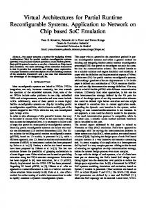
while user1 is watching her exciting film, user2 can use part of the unoccupied hardware resources to enjoy listening to his favorite song without interrupting other user tasks running (e.g., the task used by user3 to listen to her favorite radio station) as illustrated in Figure 1.1. In this thesis, we target runtime reconfigurable systems that integrate tightly coupled general-purpose processor and a reconfigurable device, e.g., FPGA. This chapter provides the overview of the research presented in this dissertation. The main problems in runtime reconfigurable systems, addressed in this dissertation, are introduced in Section 1.1. In Section 1.2, we discuss briefly the main contributions of our work. The overall organization of this dissertation is presented in Section 1.3.
1.1 Problem Overview Current devices used in runtime reconfigurable systems have the ability to reconfigure parts of their hardware resources without interrupting the normal operation of processing elements instantiated on the remaining fabric. Run time configuration has been used in several application areas and implementations, e.g., network crossbar switches [2], image interpolation [3], video coding [4], cryptography [5], neural network implementation [6], image processing [7], image compression [8], filters [9], matrix multiplications [9], motion estimation [10], mechatronics [11], Viterbi decoding [12] [14], multimedia player [13], Department of Defense (DOD) systems [15], Reed-Solomon
1.1. P ROBLEM OVERVIEW
3
Coder/Decoder [16], among many others. Exploiting partially reconfigurable devices for runtime reconfigurable systems can offer reduction in hardware area [6] [3] [4] [5] [8] [9] [11] [13], power consumption [5] [10] [12] [14] [61] [83] [84], economic cost [5], bitstream size [15], and reconfiguration time [15] [16] [83] [154] in addition to performance improvements [5] due to better resource customization. To make better use of these benefits, one important problem that needs to be addressed is hardware task scheduling and placement. Since hardware tasks are allocated and deallocated dynamically at runtime, the reconfigurable fabric can suffer of fragmentation. This can lead to undesirable situations where tasks cannot be allocated even if there would be sufficient free area available. As a result, the overall system performance will be penalized. Therefore, efficient hardware management of resources is very important. Hardware task scheduling and placement algorithms can be divided into two main classes: offline and online. Offline assumes that all task properties (e.g., arrival times, task sizes, execution times, and reconfiguration times) are known in advance. The offline version can then perform various optimizations before the system is started. In general, the offline version has much longer time to optimize system performance compared to the online version. However, the offline approach is not applicable for systems where arriving tasks properties are unknown beforehand. In such general-purpose systems, the online version is the only possible alternative. In contrast to the offline approach, the online version needs to take decisions at runtime; as a result, the algorithm execution time contributes to the overall application latency. Therefore, the goal of the online scheduling and placement algorithms is not only to produce better scheduling and placement quality, they also have to minimize the runtime overhead. In this thesis, we focus on online scheduling and placement since we strongly believe it represents a more genetic situation. The online algorithms have to quickly find suitable hardware resources on the partially reconfigurable device for the arriving hardware tasks. In cases when there are no available resources for allocating the hardware task at its arrival time, the algorithms have to schedule the task for future execution. Field-Programmable Devices (FPDs) are integrated circuits that can be (re)configured by their end users to implement various digital functions [17]. There are three FPD main categories: Simple Programmable Logic Devices (SPLDs), Complex PLDs (CPLDs) and Field-Programmable Gate Arrays (FPGAs) [17]. The main difference between PLDs and FPGAs is in the available number of logic inputs and the available logic capacities. While FPGAs
4
C HAPTER 1. I NTRODUCTION
have much higher logic capacity (and flip-flop to logic ratio), CPLDs offer more logic inputs. Advantages of using field-programmable devices (FPDs) in runtime reconfigurable systems are instant manufacturing turnaround, reduced start-up costs, low financial risk, short time-to-market and easy design changes [17]. However to get these benefits, the users need to pay additional costs: higher power consumption (approximately 12x larger dynamic power), larger silicon areas (40x more area required) and lower operating speeds (3.2x slower), as compared to the ASICs [18]. Higher power consumption requires expensive packaging [19] [20] [21], shortens chip life-times [19], asks for costly cooling systems [19] [20] [21], decreases system reliability [21] and prohibits battery operations [19] [20] [21]. Therefore, reducing the power consumption of FPDs (CPLDs and FPGAs) is a critical issue. An FPGA device can be used to build arbitrary hardware circuits (same as any ASIC could implement) by reconfiguring and interconnecting its configurable logic elements (LEs) in different ways. Each LE contains a lookup table (LUT) as a configurable combinational circuit and a flip-flop (FF) as a storage element. A group of LEs forms configurable logic block (CLB). The CLB is the basic logic element used by Xilinx FPGAs. A somehow similar approach is used by Altera to organize LEs in clusters called logic array blocs (LABs). The complexity of the FPGAs in terms of available CLBs or LABs is growing very fast with the CMOS technology improvements and now allows the implementation of complete systems. Modern FPGAs can be used to implement circuits with complexity up to 474240 LUTs and 948480 FFs as shown in Table 1.1. The FPGA device can be reconfigured by changing the content of its configuration memory. The configuration memory content, called bitstream (BS) can be up to 185 Mbits and has to be transported to the FPGA internal memory using a dedicated configuration data path. Configuration data paths have usually limited bandwidth, hence, the time needed to send the configuration bits (called reconfiguration time) can be up to 58 ms for current technology with 32-bit wide configuration data path operating at 100 MHz. High reconfiguration time overhead can eclipse the benefits of dynamically reconfigurable systems. Therefore, it is very important to address this overhead. In addition, to use the FPGA resources more effectively and to cope with FPGA area fragmentation during runtime, one needs to easily reorganize the positions of running tasks, hence fast relocation is also necessary. In this thesis, we assume pre-designed hardware tasks where for each task at least two options for execution exist: as software task on general-purpose processor or as hardware unit on the reconfigurable fabric. In the assumed system, each task can arrive at any time and its properties are unknown to the sys-
1.1. P ROBLEM OVERVIEW
5
Table 1.1: Virtex FPGAs FPGAs Virtex-4 Virtex-5 Virtex-6
LUTs 178176 207360 474240
FFs 178176 207360 948480
Bitstream size(Mbits) 51 83 185
Reconfiguration time(ms) 16 26 58
tem beforehand. This models real situations in which the time when the user requests system resources for his/her usage is unknown. As a result, the envisioned system has to provide support for runtime hardware tasks placement and scheduling since this cannot be done statically at system design time. Similar to other work (e.g., [22]- [53]), we assume that each hardware task requires reconfigurable area with rectangular shape and can be placed at any location on the reconfigurable device. Our task model includes all required reconfigurable units and interconnect resources. Each hardware task is defined by three parameters: its area (width and height in terms of atomic reconfigurable units), reconfiguration time, and its execution time (the latter two expressed in system clock cycles). The software tasks that are identified for hardware acceleration are first designed using a hardware description language and after that are placed and routed by commercial FPGA synthesis CAD tools to obtain functionally equivalent modules that can replace their respective software versions. At this step of the design process we can use the synthesis results to extract the task sizes for the used FPGA fabric. The output of the synthesis is the configuration bitstream that should be loaded to the device using its integrated configuration infrastructure. Therefore, starting from the task bitstream file, we can obtain precisely its reconfiguration time on the targeted technology. The two key ingredients are the configuration data size (the bitstream length in number of bits) and the throughput of the internal FPGA configuration circuit. As an example, the Internal Configuration Access Port (ICAP) of Virtex 4 FPGAs from Xilinx can transport 3200 million bits/second and will load a bitstream of size 51 Mbits in 15.9ms. The last parameter, the task execution time is specified by the time needed to process a unit of data (referred as: Execution Time Per Unit of Data, ETPUD) and the overall data size to be processed (i.e. how much data need to be processed). Please note that for some applications, the task execution time is also dependent on the exact data content (e.g., as in the case of Viterbi and Context-Adaptive Binary Arithmetic Coding (CABAC)). In such applications, even when processing the same amount of data, the elapsed time will be different when the input data content changes. To address data dependent task execution times, we envision two solutions: worst case execution
6
C HAPTER 1. I NTRODUCTION
time scenario and notification on task completion HW support. In this thesis, we assume the worst case execution time scenario in which we use the task execution time when processing the worst case input data content. In such scenario, it is possible that the actual task completion can happen earlier than the scheduled completion time resulting in idle times that can not be used by the scheduler. In addition, such tasks will cause additional wasted area that cannot be utilized immediately by other HW tasks. In such non-optimal scenario, however, the overall computing system will operate correctly. Please note that the chosen scenario is the worst case in respect to the proposed placement and scheduling algorithms due to the introduced overheads in task execution time and wasted area. The second solution requires dedicated hardware support for feedback signaling when the running tasks complete, however, as mentioned earlier this can additionally improve the overall system performance. Some existing systems already have the necessary ingredients required to implement such support. For example, in the Molen architecture [203], the sequencer is aware of the hardware (HW) task start and completion timing. The only necessary extension in this case is to provide a way to pass this information to the HW scheduler and make it aware of running tasks completion. With this knowledge, the HW scheduler can make data content dependent tasks scheduling more efficient. This approach is outside of the scope of this thesis without loosing generality of our proposal. Even more the selected worst case execution scenario is less beneficial for the scheduling and placement algorithms presented in this thesis. We are strongly convinced that both types of systems will be able to benefit from the proposed algorithms. The assumed overall system model used in our study is depicted in Figure 1.2 consisting of two main devices: the general-purpose processor (GPP) and the reconfigurable device (FPGA). All hardware task bitstream images are available in a repository resuming in the main memory (not explicitly shown on the figure) and can be requested by any running application on the GPP by using a dedicated operating system (OS) call. In response to such request, the OS will invoke the Placer (P) to find the best location on the FPGA fabric for the requested hardware task. Once appropriate location is found, the Translator will resolve the coordinates by transforming the internal, technology independent model representation to the corresponding low level commands specific for the used FPGA device. The Loader reads the task configuration bitstream from the repository and sends it to the internal configuration circuit, e.g., ICAP in case of Xilinx, to partially reconfigure the FPGA at the specific physical location provided by the Translator. After reconfiguring the FPGA fabric the requested hardware task execution is started immediately to avoid idle hardware units on
1.1. P ROBLEM OVERVIEW
7
Memory Buses Area for Loader
P or P+S
Translator
OS
Hardware Tasks ICAP
T2 T1 T3
GPP
T4
Static Area
GPP /FPGA
T5
Dynamic Area
FPGA
Figure 1.2: System Model (OS: operating system, P: placer, S: scheduler)
the reconfigurable fabric. For systems with combined Placer and Scheduler (P+S), when the hardware area is fully occupied, the Scheduler (S) schedules the task for future execution at predicted free area places at specific locations and specific starting times. For systems with only Placer (P), in cases when no hardware resources are available the corresponding task can be executed using its software version with significant and often unpredictable execution time penalty. The Loader can be implemented at either the general-purpose processor (GPP) as OS extension or in the Static Area of the FPGA. If the Loader is implemented in the GPP, the communication between the Loader to the ICAP is performed using the available off-chip connection. For implementations in the FPGA, the Loader connects to the ICAP internally. Similar to [202], dedicated buses are used for the interconnect on chip. Those buses are located at every row of the reconfigurable regions to allow data connections between tasks (or tasks and I/Os) regardless of the particular task sizes. To illustrate the above processes at different stages of the system design and normal operation, we will use a simple example of hardware task creation as depicted in Figure 1.3. The hardware task in our example is a simple finite impulse response (FIR) filter. The task consumes input data from array A[i] and produces output data stored in B[i], where B [i ] = C 0∗A [i ]+C 1∗A [i +1]+ C 2 ∗ A [i + 2] + C 3 ∗ A [i + 3] + C 4 ∗ A [i + 4] and all data elements are 32 bits
8
C HAPTER 1. I NTRODUCTION
BS Address A[i]
FIR.vhd
B[i]
BS Length TPA Task Width(wi) Task Height(hi) ETPUD
CAD tools
wi=33 CLBs
Task Parameters Configuration
FIR.bit
Input Data Address Output Data Address C0 C1 C2 C3 C4
hi=32 CLBs
Data For
Execution time per unit data (ETPUD): 1415 cycles for processing 100 32-bit data at 11 ns clock period
Input Data (size=5000 32-bit) Output Data (size=5000 32-bit)
Data
Set BS Address
Code
FIR (size=BS length)
Task Configuration FPGA
Microcode
Program
Figure 1.3: System at Design Time
wide. The task implementation described using a hardware description language (HDL) (FIR.vhd) is synthesized by commercial CAD tools that produce the partial bitstream file (FIR.bit) along with the additional synthesis results for that task. The bitstream contains the configuration data that should be loaded into the configuration memory to instantiate the task at a certain location on the FPGA fabric. The synthesis results are used to determine the rectangle area consumed by the task in terms of configurable logic blocks (CLBs) specified by the width and the height of the task. In our example, the FIR task width is 33 and the task height 32 CLBs for Xilinx Virtex-4 technology. Based on the synthesis output we determine the tasks reconfiguration times. Please note, that in a realistic scenario one additional design space exploration step can be added to steer task shapes toward an optimal point. At such stage, both, task sizes and reconfiguration times are predicted by using high-level models as the ones described in [54] in order to perform quick simulation of the different cases without the need of synthesizing all of the explored task variants. For example in Virtex-4 FPGA technology from Xilinx, there are 22 frames per column and each frame contains 1312 bits. Therefore one column uses 22x 1312 = 28864 bits. Since our FIR HW task requires 33 CLBs in 2 rows of 16 CLBs totaling in 32 CLBs, we obtain a bitstream with 33x 2x 28864 = 1905024 bits. Virtex-4 ICAP can send 32-bit data every 100 MHz clock cycle, hence, we can estimate the reconfiguration time as 1905024x 10/32 = 595320 ns. Next,
1.1. P ROBLEM OVERVIEW
9
BS Length TPA Task Width(wi) Task Height(hi) ETPUD
Task Properties
FIR(r,c)
FIR.bit Task Configuration Microcode FIR
OS
P FIR’=FIR(r’,c’) or P+S
FIR’’=FIR(r”,c”) Translator
Loader FIR”
c r’
r r”
FIR
c’
c” FIR’
Area Model
FIR”
FPGA
Figure 1.4: System at Runtime
the FIR task is tested by the designer to determine how fast the input data can be processed. For our example from Figure 1.3, the task needs 1415 cycles to process 100, 32-bit input data elements at 11 ns clock period making its ETPUD 1415x 11 = 15565 ns per 100, 32-bit unit data. Based on the above ETPUD number, we can estimate the task execution time for various input data sizes. In our example, there are 5000, 32-bit input data elements that have to be processed by the FIR HW task. Therefore, the expected execution time of our FIR task is (5000/100)x 15565 = 778250 ns (778ms). The configuration data and task specific information are merged together in what we call a Task Configuration Microcode (TCM) block as shown in the upper part of Figure 1.3. TCM is pre-stored in memory at the Bitstream (BS) Address. The first field, the BS length represents the size of the configuration data field. This value is used by the Loader when the task is fetched from memory. The task parameter address (TPA) is needed to define where the task input/output parameters are located. In Figure 1.3, the task parameters are the input and output data locations, the number of data elements to be processed and the FIR filter coefficients (C0-C4). The input data address gives the location where the data to be processed remains. The location where the output data should be stored is defined by the output data address. During runtime, when the system needs to execute the FIR hardware task on
10
C HAPTER 1. I NTRODUCTION
the FPGA, the OS invokes the Placer (P) to find a location for it (shown as example, in Figure 1.4). From the TCM the Placer gets the task properties information: task width, task height, reconfiguration time, and its execution time. Based on the current state of the used area model, the Placer searches for the best location for the task. When the location is found (in this example: r ′ and c ′ ), the task is placed in the area model and its state is updated as shown on the left side of the figure. The Translator converts this location into real physical location on the targeted FPGA. In the bitstream file (FIR.bit), there is information about the FPGA location where the HW task was pre-designed (in this figure: r and c). By modifying this information at runtime, the Loader partially reconfigures the FPGA through the ICAP (by using the technology specific commands) at the location obtained from the Translator (r ′′ and c ′′ in this example). By decoupling our area model from the fine-grain details of the physical FPGA fabric, we propose an FPGA technology independent environment where different FPGA vendors, e.g., Xilinx, Altera, etc, can provide their consumers with full access to partial reconfigurable resources without exposing all of the proprietary details of the underlying bitstream formats. On the other side, reconfigurable system designers can now focus on partial reconfiguration algorithms without having to bother with all low-level details of a particular FPGA technology.
1.2 Research Questions and Main Contributions As discussed in Section 1.1, efficient runtime reconfigurable systems management has to cope with the three main challenges: minimal hardware use, minimal power consumption, and minimal reconfiguration overhead. In respect to the above challenges the thesis at hand will provide an answer to the following research questions: 1. How to improve area utilization, application execution time and algorithm overhead of hardware task placement and scheduling approaches? 2. How to reduce the power consumption of reconfigurable devices by improving their basic logic elements? 3. Can hardware task reconfiguration overhead be reduced by revisiting the configuration infrastructure? This dissertation elaborates on the above three questions critical for all modern runtime partially reconfigurable systems. The work contained in this disserta-
1.3. D ISSERTATION O RGANIZATION
11
tion provides evidence that the aforementioned questions can be successfully answered. More specifically, the main contributions of this thesis are: 1. Novel online hardware task scheduling and placement algorithms on partially reconfigurable devices with higher quality and shorter algorithm execution time compared to the state of the art; 2. A novel logic element for FPDs with reduced power consumption compared to the industrial FPDs; 3. Low overhead FPGA configuration circuit architectural extensions to shorten the reconfiguration and relocation times compared to current high-end FPGA devices.
1.3 Dissertation Organization This dissertation consists of the following chapters: • Chapter 2 gives an overview of the state of the art in solving problems in runtime reconfigurable systems. It presents a survey on existing online hardware task scheduling and placement algorithms, techniques to reduce power consumption in reconfigurable devices, and techniques to reduce reconfiguration overhead in runtime reconfigurable systems. • Chapter 3 introduces two novel algorithms to deal with online hardware task placement problem in runtime reconfigurable systems on partially reconfigurable devices. The first algorithm (Intelligent Merging) deals with reducing algorithm execution time by avoiding unnecessary operations. The algorithm run up to 3x faster than related art with 0.89 % less placement quality. The second one (Quad-Corner) is more challenging, the aim is to discover a faster algorithm yet with a higher quality. The algorithm not only has higher placement quality (78 % less penalty and 93 % less wasted area) than related art but also has lower runtime overhead. • Chapter 4 presents two novel online hardware task scheduling and placement algorithms on partially reconfigurable devices. The first algorithm (Intelligent Stuffing) is designed for 1D area model. The algorithm outperforms related art in terms of reduced total wasted area up to 89.7 %, has 1.5 % shorter schedule time and 31.3 % shorter waiting time. The
12
C HAPTER 1. I NTRODUCTION
second one (3D Compaction) is proposed for 2D area model. The algorithm has up to 4.8 % shorter schedule time, 75.1 % shorter waiting time, and 22.9 % less wasted volume compared to related art. • Chapter 5 describes a novel low power logic element (LE) for FPDs. FPDs using our proposal consume 6-90 % less total power and run 2-33 % faster than FPDs using conventional LEs. • Chapter 6 shows a novel configuration circuit architecture for fast reconfiguration and relocation. The architecture can speedup reconfiguration and relocation by 4x and 19.8x on average, respectively. • Chapter 7 summarizes our findings and gives some suggestions for future research directions.
2 Related Work
A
s presented in Chapter 1, this dissertation targets three major problems in current runtime partially reconfigurable systems: online hardware task scheduling and placement, power consumption, and runtime reconfiguration overhead. Before presenting our proposal of how to address these problems in more detail, in this chapter, we present related work published by other researchers in their attempts to address the same problems. This chapter is organized as follows. In Section 2.1, we discuss existing online task placement algorithms for partially reconfigurable devices. Related art regarding online task scheduling and placement is presented in Section 2.2. This section is short because work in this area is quite recent. In Section 2.3, we survey existing techniques for reducing power consumption in FPDs. Related work for reducing reconfiguration overhead is addressed in Section 2.4. Finally, we conclude this chapter in Section 2.5.
2.1 Online Hardware Task Placement Algorithms In [22], Bazargan et al. proposed two algorithms: Keeping All Maximal Empty Rectangles (KAMER) and Keeping Non-overlapping Empty Rectangles (KNER). An empty rectangle is a rectangle area that can be used to place a task without overlapping to any running tasks on the FPGA. Such rectangle is used to place each arriving task at runtime. The two algorithms (KAMER and KNER) differ mainly in the way the empty rectangle is partitioned during task placements as shown in Figure 2.1. If the rectangle cannot be expanded anymore, the authors refer to it as a Maximal Empty Rectangle (MER); otherwise they call it a Non-overlapping Empty Rectangle (NER). KAMER organizes all MERs, whereas KNER manages all NERs. If there is an arriving task, both algorithms search all empty rectangles (i.e. MERs for KAMER or NERs 13
14
C HAPTER 2. R ELATED W ORK
for KNER) to find a suitable one which can fit the arriving task based on one of two-dimensional bin-packing heuristics: First Fit (FF), Best Fit (BF), and Bottom-left (BL). In KNER, only the selected empty rectangle is split into two smaller ones due to non-overlapping empty rectangles to decrease algorithm execution time of KAMER. The splitting can be done in one of two different ways: vertical split or horizontal split. For example, in Figure 2.1, the KNER decides to do vertical split after placing task T1 and horizontal split after placing task T2. Every time the algorithm places the task, it performs splitting operation. If it just splits the empty rectangles and does not merge them, FPGA will be partitioned into smaller and smaller of many empty rectangles. This situation will make placement quality worse, so the algorithm needs to do both merging and splitting operations. The split decision in KNER is made by utilizing one of these heuristics: Shorter Segment (SSEG), Longer Segment (LSEG), Square Empty Rectangles (SQR), Large Square Empty Rectangles (LSQR), Large Empty Rectangles (LER), and Balanced Empty Rectangles (BER). Although the authors have proposed these heuristics to avoid wrong splitting decisions, wrong decisions still cannot be totally avoided, lowering the placement quality of KNER. For example, in Figure 2.2, although the FPGA has enough free area for a new incoming task, KNER rejects it due to its incorrect splitting decision in the past.
Vertical MER
NER
T1
T1 MER
NER
MER
NER MER
T1
Split
T2
NER
T1 MER
a. KAMER
T2
Horizontal Split NER
b. KNER
Figure 2.1: KAMER vs KNER
In [23] and [24], Tabero et al. proposed a Vertex-list algorithm. Vertex List Set (VLS) data structure is used that each of the lists describes the contour of each unoccupied area fragment in the FPGA. The authors use bottom-left or topright heuristic for placing arriving tasks on vertexes. The VLS structure is a
2.1. O NLINE H ARDWARE TASK P LACEMENT A LGORITHMS
A running or placed task
15
A new arriving or incoming task
Figure 2.2: A rejection of an arriving task due to its previous wrong splitting decision
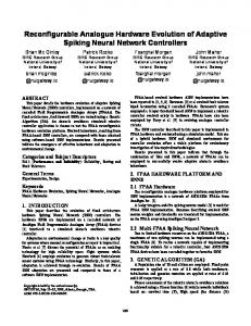
geometrical description of the whole FPGA free area perimeter. Instead of partitioning free areas as KAMER and KNER, the Vertex-list algorithm focuses on the free area perimeter for placing an arriving task. The algorithm places a task on one of the corners of this free area perimeter based on one of two heuristics: 2D-adjacency-based and fragmentation-based. The 2D-adjacencybased heuristic inserts the task on the vertex position that has the highest contact level in space of the task to the running tasks and the FPGA boundary, while the fragmentation-based heuristic inserts the task on the vertex position that has the lowest fragmentation level. To enhance placement quality of their Vertex-list algorithm, in [25], they proposed two new heuristics: 3D-adjacency and Look-ahead 3D. In addition to the contact level in space, the 3D-adjacency heuristic also computes the contact level in time to pack tasks in space and time. In Look-ahead 3D heuristic, the 3D-adjacency value is computed not only at current time but also at the future time when the next running task is finished. After computing all the 3D-adjacency values, the task is placed at the position with the highest 3D-adjacency value. In [26] and [27], Steiger et al. and Walder et al. proposed an On The-Fly (OTF) algorithm. As mentioned earlier, the wrong split decision can lower the placement quality of KNER. To avoid such wrong decisions, they modified KNER by delaying the split decision until a next arrived task placed on the FPGA. However, for this modification, they need to resize several rectangles on a task insertion. In [28], Morandi et al. proposed a Routing Aware Linear Placer (RALP) algo-
16
C HAPTER 2. R ELATED W ORK
rithm. The algorithm is a modified version of KNER algorithm with an additional routing cost consideration between dependent tasks. Tasks are placed on empty rectangles that have the least Manhattan distances between dependent tasks to minimize routing cost. The algorithm can reduce routing cost compared to KNER as reported in [28]. However, it has a lower placement quality that KNER due to the negative impact of its routing consideration. In [29], Ahmadinia et al. proposed a Horizontal Line (HL) algorithm to manage free space and the Clustering Based (CB) strategy to improve the placement quality of their HL approach. Instead of managing a list of empty rectangles like in KAMER, KNER [22], and OTF [26] [27], HL uses exactly two horizontal lines for placing the task; one above (top horizontal line) and one below (bottom horizontal line) the placed tasks. In order to store information on these horizontal lines, HL uses two separate linked-lists. HL is implemented in such a way that hardware tasks are placed above the currently running tasks as long as there is free space. Once there is no empty space found above the running tasks, the new ones start to be placed below them and so on. The basic idea of CB is to place all tasks with similar end times in the same strip such that a large empty space will be created at a certain location at the end time. This new empty space hopefully will be able to accommodate future larger tasks.
1
−5 −4 −3 −2 −1 1
1
2
−5 −4 −3 −2 −1 2
2
3
1
1
1
1
1
3
3
4
2
2
2
2
2
4
4
5
3
3
3
−3 −2 −1
6
4
4
4
−3 −2 −1 6
5
Figure 2.3: Area matrix of the staircase algorithm
In [30] and [31], Handa et al. proposed the Staircase algorithm for finding MERs. A 2D array, referred as area matrix, for modeling the FPGA surface with each cell in the array representing a CLB is used. For example, an FPGA (8x6 CLBs) with two running tasks (5x2 CLBs and 3x2 CLBs) is modeled with an area matrix in Figure 2.3. Every CLB array cell in the free area contains a positive number that gives the number of continuous empty cells in the column above including the cell itself. Every cell in the occupied area holds a negative number that represents the remaining width of the task measured on
2.1. O NLINE H ARDWARE TASK P LACEMENT A LGORITHMS
17
T5 T4 T3 Staircase
T2
T1
Figure 2.4: A staircase
the right side from that cell. The area matrix is used for constructing staircases and finally these staircases are utilized for finding MERs. All the empty rectangles having same bottom right coordinate make a staircase as illustrated in Figure 2.4. They only check maximal staircases for extracting MERs. After a maximal staircase is detected, all the rectangles in the staircase can be checked to see if they are MERs. 1
2
3
4
5
6
7
8
9
0
0
0
0
1
2
0
0
0
0
0
0
0
1
2
0
0
0
1
2
3
4
5
6
0
0
0
1
2
3
4
5
6
0
0
0
1
2
3
4
5
6
7
8
9
Figure 2.5: Area matrix of SLA
In [32], Cui et al. proposed the Scan Line Algorithm (SLA) algorithm for finding MERs. The authors use the same area matrix as the staircase algorithm with a different encoding to represent the FPGA area. For example, an FPGA (9x6 CLBs) with two running tasks (4x2 CLBs and 3x4 CLBs) is modeled with an area matrix in Figure 2.5. Every free area CLB is represented by a positive number that gives the number of continuous empty cells on left including that cell as shown in Figure 2.5. Every occupied CLB is represented by a zero. In SLA, the area matrix is used for finding Maximum Key Elements (MKEs)
18
C HAPTER 2. R ELATED W ORK
and finally these MKEs are scanned for finding all MERs. A key element is an empty cell with an occupied cell as its right hand neighbor. A column that contains one or more key elements is called as a scan line. A scan line is partitioned into segments by valley points. A valley point is the element within a scan line where values in the line starting to increase. Each segment has one MKE which is the largest key element in the corresponding segment. In [33], Xiao et al. discovered that the SLA algorithm can find empty rectangles that are not MERs. To solve this problem, they proposed ESLA algorithm in [33]. Before the algorithm scans each MKE for finding MERs, the algorithm is instrumented with an ability to know a set of valid widths for that corresponding MKE. By doing so, the algorithm only needs to scan an MKE for those valid widths. To avoid duplicated scanning, the algorithm records a set of scanned positions during each MKE scanning. 7,4,0 7,4,0 7,4,0 7,2,0 7,2,0 7,2,0 7,6,0 7,4,0 7,4,0 7,4,0 7,2,0 7,2,0 7,2,0 7,6,0 3,4,0 3,4,0 3,4,0 3,4,9 3,4,9 3,4,9 1,6,0 3,4,0 3,4,0 3,4,0 3,4,9 3,4,9 3,4,9 1,6,0 3,2,8 3,2,8 3,2,8 3,4,9 3,4,9 3,4,9 1,6,0 3,2,8 3,2,8 3,2,8 3,4,9 3,4,9 3,4,9 1,6,0 Figure 2.6: Fragmentation matrix of CF
In [34], Cui et al. proposed the Cell Fragmentation (CF) algorithm for their online placement algorithm. CF uses the SLA to find MERs and a Fragmentation Matrix (FM) to represent the area of the FPGA. For example, an FPGA (7x6 CLBs) with two running tasks (3x2 CLBs and 3x4 CLBs) is modeled with a fragmentation matrix in Figure 2.6. For empty cells, each cell is labeled by the number of contiguous empty cells in horizontal, in vertical direction, and a zero. For occupied cells, each cell is labeled by the number of contiguous occupied cells in horizontal, in vertical direction, and the finish time of the task. In order to place a task on the FPGA, CF calculates the Time-Averaged Area Fragmentation (TAAF) for all MERs that are large enough to accommodate the task and then places the task into one of the MERs which has the largest TAAF. The TAAF of a MER is the degree of impact of this MER on the overall
2.1. O NLINE H ARDWARE TASK P LACEMENT A LGORITHMS
19
degree of fragmentation. A MER with large TAAF means it has more impact on the overall degree of fragmentation, that’s why CF places the arriving task to a MER that has the largest TAAF. In [35] and [36], Tomono et al. proposed an online FPGA algorithm that does not only take into consideration the degree of fragmentation, but also the speed of I/O communication computed based on the Manhattan distances. The aim of their algorithm is to balance the degree of fragmentation and the speed of I/O communication. They use the same area matrix data structure as used by the Staircase algorithm with additional I/O communication constraints, so they increase the degree of fragmentation in order to gain the speed of I/O communication. Because of this additional consideration, they need to check the status of each communication channel during staircase creation. In [37] and [38], Ahmadinia et al. proposed the Nearest Possible Position (NPP) algorithm. They manage the occupied space rather than the free space, because the set of empty rectangles grows much faster than the set of placed rectangles. The impossible placement region (IPR) of an arriving task relative to a placed task is the region near the placed task where it is impossible to place this arriving task without overlapping the placed task. The possible placement region (PPR) is the area where it is possible to place the arriving task without overlapping any placed tasks. In order to find the best position on the PPR for placing an arriving task, they compute the routing cost based on Euclidean distances and place an arriving task at the optimal point, where routing cost is minimum. If they cannot find the optimal point on the PPR, they will find the Nearest Possible Position (NPP) for placing the task. In [39], Lu et al. proposed the Multi-Objective Hardware Placement (MOHP) algorithm. The algorithm uses the VLS data structure adopted from [23] and [24]. Incoming tasks are classified into three groups with different treatments. The first group is for independent tasks that need to be executed urgently due to short remaining time to the deadline. To handle tasks in this group, the algorithm uses the FF heuristic for fast allocation. The second group is for independent tasks that do not need urgent treatment. For this group, the algorithm adopts a vertex-list approach from [23] and [24]. The third group is for dependent tasks. In this group, the routing between dependent tasks needs to be shortened. For that reason, the algorithm utilizes the NPP approach adopted from [37] and [38] for tasks in this group. In [40], Elbidweihy and Trahan proposed an online placement algorithm that manages both Maximal Horizontal Strips (MHS) and Maximal Vertical Strips, called the Maximal Horizontal and Vertical Strips (MHVS) algorithm. MHSs
20
C HAPTER 2. R ELATED W ORK
are rectangles generated by partitioning free area using top and bottom boundaries of running tasks; whereas MVSs are rectangles that result from free area partitioning using left and right boundaries of running tasks. In this algorithm, the first fit rectangle is used for placing an arriving task. The algorithm can run faster compared to KAMER as reported in [40]. However, it has a lower placement quality than KAMER. In [41] and [42], Ahmadinia et al. proposed the Routing-Conscious Placement(RCP). In order to reduce free-space management to a single point, they expand inserted modules and concurrently shrink the FPGA area and an arriving task by half both in width and height. To choose the position for placing an arriving task, they choose a position, such that the weighted communication cost computed based on the Manhattan distances is minimized. In [43], K¨oster et al. proposed a task placement algorithm for heterogeneous reconfigurable architectures, TPHRA. The basic idea of this algorithm is to avoid placing an arriving task with many feasible positions in areas that can be used by tasks with few feasible positions whenever possible. In [44], Ahmadinia and Teich proposed the Least Interference Fit (LIF) algorithm. In order to reduce the reconfigurable overhead due to the limitation of currently available FPGA technology in that time (column-wise reconfigurable capability), LIF places tasks at the position where the tasks interfere with the currently running tasks as little as possible.
1/5 1/2 1/2 1/3
T2 T1
T3
Figure 2.7: FAP
In [45], ElFarag et al. proposed the Fragmentation-Aware Placement (FAP) algorithm. In this paper, they introduced a fragmentation metric that gives an indication to the continuity of occupied (or free) space on the reconfigurable device and not the amount of occupied (or free) space. The algorithm places each arriving task on the location where the fragmentation metric is smallest. All empty spaces have to be tested before it can select one that causes the lowest fragmentation. Figure 2.7 shows how they compute the fragmentation metric. There are three tasks (T1, T2, and T3) placed on a reconfigurable device with size of 5x5 reconfigurable units. In the first row of reconfigurable
2.2. O NLINE TASK S CHEDULING
AND
P LACEMENT
21
device, there is one contiguous empty space that consists of five reconfigurable units, therefore the fragmentation in this row is 1/5. Using similar way, the total row fragmentation is ((1/5) + (1/2) + (1/2) + (1/3)), while the total column fragmentation is ((1/1) + (1/1) + (1/1) + (1/1) + (1/4) + (1/4)).
2.2 Online Task Scheduling and Placement In [46] and [47], Steiger et al. proposed the Horizon and Stuffing algorithms both for 1D and 2D area models. The Horizon guarantees that arriving tasks are only scheduled when they do not overlap in time or space with other scheduled tasks. The Stuffing schedules arriving tasks to arbitrary free areas that will exist in the future by imitating future task terminations and starts. In these papers, the authors reported that the Stuffing algorithm outperforms the Horizon algorithm in scheduling and placement quality. Space (Column)
Space (Column)
Space (Column)
T1
T1
T1 T2
T2
T3 Time
Time
Time
a. Stuffing Space (Column)
Space (Column)
Space (Column)
T1
T1
T1 T2
T2 T3
Time
Time
Time
b. Classified Stuffing
Figure 2.8: Stuffing vs Classified Stuffing
Discovered that the problem of the Stuffing that always places a task on the leftmost of its free space as shown in Figure 2.8a, Chen and Hsiung in [48] proposed their 1D Classified Stuffing. By classifying incoming tasks before scheduling and placement, the 1D Classified Stuffing performs better than the original 1D Stuffing. For example, because the Stuffing algorithm always places tasks on the leftmost edge of the available area, it places tasks T1 and T2 as shown in Figure 2.8a. These placements block task T3 to be scheduled earlier. In this case, the Stuffing fails to place task T3 earlier. The main difference between the Classified Stuffing and the Stuffing is the classification of
22
C HAPTER 2. R ELATED W ORK
tasks. The Classified Stuffing can place a task on the leftmost or rightmost of its free space based on the task Space Utilization Rate (SUR). SUR is the ratio between the number of columns required by the task and its execution time. High SUR tasks (SUR > 1) are placed starting from the leftmost available columns of the FPGA space, while low SUR tasks (SUR ≤ 1) are placed from the rightmost available columns. For this simple example, the Classified Stuffing can recognize the difference between tasks T1 (high SUR task) and T2 (low SUR task), so it places successfully tasks on different sides as shown in Figure 2.8b. Therefore the task T3 can be scheduled earlier by the Classified Stuffing, outperforming the Stuffing as reported in [48]. In [49], Marconi et al. proposed their 1D Intelligent Stuffing to solve the problems of both the 1D Stuffing and Classified Stuffing. The main difference between their algorithm and the previous 1D algorithms is the additional alignment flag of each free segment. The flag determines the placement location of the task within the corresponding free segment. By utilizing this flag, the 1D Intelligent Stuffing outperforms the previously mentioned 1D algorithms. In [50], Lu et al. introduced their 1D reuse and partial reuse (RPR). The algorithm reuses already placed tasks to reduce reconfiguration time. As a result, the RPR outperforms the 1D Stuffing. In [51], Zhou et al. proposed their 2D Window-based Stuffing to tackle the drawback of 2D Stuffing. By using time windows instead of the time events, the 2D Window-based Stuffing outperforms previous 2D Stuffing. The drawback of their 2D Window-based Stuffing is its long execution time. To reduce this runtime cost the authors proposed the Compact Reservation (CR) in [52]. The main idea of the CR is the computation of the earliest available time (EA) matrix for every incoming task. That contains the earliest starting times for scheduling and placing the arriving task. The CR outperforms the original 2D Stuffing and their previous 2D Window-based Stuffing.
2.3 Low Power Techniques for Reconfigurable Devices Modern FPGAs contain embedded hardware blocks, such as: multipliers, DSPs, and memories. It is reported in [18] [61] that mapping designs to these blocks can reduce power consumption. The design that uses hard blocks requires less interconnection. As a result, static and dynamic power consumptions are reduced. Adding programmable delay circuits into configurable logic blocks is reported
2.3. L OW P OWER T ECHNIQUES
FOR
R ECONFIGURABLE D EVICES
23
in [68] to reduce power consumption in FPGAs. The generation of glitches is avoided by aligning the arrival times of signals using the proposed programmable delay circuits. As a result, the glitched are reduced for minimizing dynamic power consumption. To reduce dynamic power consumption in FPGAs, circuits are pipelined in [64] [65] [66]. This technique reduces the number of levels of the circuit between registers by dividing the circuit into stages. A circuit with lower levels tends to produce fewer glitches. Since a circuit with fewer glitches consumes less dynamic power, the power consumption is reduced. Reducing power consumption in FPGAs by inserting negative edge triggered flip-flops at the outputs of selected LUTs to block glitches for propagating further is reported in [71]. Since the technique produces a circuit with fewer gliches, the dynamic power consumption is reduced. Retiming can be used to reduce dynamic power consumption in FPGAs [67]. The idea is to redistribute registers along a signal path without changing the functionality of the circuit. By doing so, the logic between registers is minimized, hence reducing glitches. As a result, the dynamic power consumption is reduced. The bit-widths of the internal signals of circuits can be optimized to reduce dynamic power consumption. A circuit with shorter bit-widths consumes less power. This approach applied in FPGAs is reported in [72] [73]. Clock gating is used to reduce dynamic power consumption by selectively blocking the circuit local clock when no state or output transition takes place as illustrated in Figure 2.9. The clock gating controller is needed for detecting the conditions of the observed circuit. Based on these conditions, the clock gating controller can know the exact time when it can stop clock signal to be transported to the specific circuit for power saving. It is used in FPGAs [74] [75] [76] [77] [61] [78] [79] [80] and CPLDs [81]. This technique is supported by commercial CAD tools from Xilinx as reported in [77]. In [80], an asynchronous FPGA with clock gating is proposed. Powering FPGAs with a variable supply voltage can also be used to reduce power consumption [82]. This method is referred as dynamic voltage scaling (DVS). Since there is a quadratic relationship between supply voltage and dynamic power, reducing the voltage will significantly reduce the dynamic power. Moreover, a cubic relationship between supply voltage and leakage power reduces significantly the leakage power. Modern FPGAs have the ability to reconfigure part of their resources with-
24
C HAPTER 2. R ELATED W ORK
Switch Circuit with state or output transitions
Clock generator
Clock Gating Controller a. Transporting clock signal for normal operation
Switch Circuit without state or output transitions
Clock generator Clock Gating Controller
b. Stop transporting clock signal for power saving
Figure 2.9: Clock gating
out interrupting the remaining resources at runtime. Hardware sharing can be realized by utilizing this partial reconfiguration feature for power consumption reduction. Power saving using this approach in FPGAs is reported in [5] [10] [12] [14] [61] [83] [84]. Clock scaling is an approach to reduce power consumption by adjusting operating clock frequency dynamically. Applying this approach in FPGAs is reported in [85]. A lower threshold voltage transistor runs faster, but it consumes more power. Multi-threshold voltage technique is to use higher threshold voltage transistors on noncritical paths to reduce static power, and low threshold voltage transistors on critical paths to maintain performance. This technique has been applied in commercial FPGAs as reported in [61] [86]. A lower capacitive circuit consumes less dynamic power. One of the ways to reduce capacitance is to use a low-k dielectric material. This technique is used by commercial FPGAs as shown in [61] [86]. A simple way for static and dynamic power savings is to reduce the supply voltage. Commercial FPGAs reported this in [61] [86]. Building circuits with bigger size lookup tables (LUTs) needs less interconnection between LUTs. As a result, interconnect power consumption is reduced. This has triggered commercial FPGA vendors to use bigger size LUTs as reported in [61] [63]. Power gating is a technique for reducing power consumption by temporarily
2.3. L OW P OWER T ECHNIQUES
FOR
R ECONFIGURABLE D EVICES
25
turning off circuits that are not in use. It is applied in FPGAs [87] [88] [89] [90] [91]. This technique is used in commercial products, such as: Atmel PLDs [93], Altera CPLDs [94], Actel FPGAs [95], QuickLogic FPGAs [96], Xilinx FPGAs [61] , Altera FPGAs [92]. In [88], an asynchronous FPGA with autonomous fine-grain power gating is proposed. How to partition a design to better benefit from power gating technique is reported in [91]. Conventional single-edge-triggered flip-flops respond only once per clock pulse cycle. To reduce power consumption, a flip-flop that can respond to both the positive and the negative edge of the clock pulse (double-edge-triggered flip-flops) was proposed in [97]. This technique is used in Xilinx CPLDs to reduce power consumption [98]. Since SRAM memory is volatile, SRAM-based FPGAs need to be reconfigured before usage. This reconfiguration consumes power. In contrast, the flash-based FPGAs (e.g. Actel FPGA [95]) that use non-volatile memory can be operated directly without reconfiguration. Powering FPGAs with two different supply voltages (dual-Vdd) can also reduce power consumption as reported in [20] [99] [100] [101] [102] [103]. It is to use lower supply voltages on noncritical paths to reduce power, and higher supply voltages on critical paths to maintain performance. Algorithms for Vdd assignment are presented in [101] [102]. [103] combines concurrently this technique with retiming to better reduce power consumption in FPGAs. Reordering input signals to LUTs can reduce dynamic power consumption in FPGAs. By doing so, we can minimize the switching activity inside LUTs as reported in [104]. Since power consumption depends linearly on the switching activity, reducing this results in power consumption improvement. Power consumption in FPGAs can be reduced by dividing a finite state machine (FSM) into two smaller sub-FSM using a probabilistic criterion [105]. The idea is to activate only one sub-FSM at a time, meanwhile the other is disabled for power reduction. Choosing state encoding of FSM for power reduction in FPGAs is reported in [106] [107]. The idea is to minimize the bit changes during state transitions for reducing switching activity, hence minimizing the dynamic power consumption. Using a diagonally symmetric interconnect pattern in Virtex-5 FPGAs can reduce the number of interconnect routing hops as reported in [108]. As a result, the interconnect power consumption is reduced. Since not all inputs of LUTs are used in real FPGA designs, leakage power can be reduced by shutting off SRAM cells and transistors associated with unused
26
C HAPTER 2. R ELATED W ORK
LUT inputs as reported in [21]. Using LUTs able to operate in two different modes (high-performance and low-power) reduces leakage power as reported in [109]. The idea is to use some transistors for lowering supply voltage across input inverters of LUTs during low power operation mode. Since not all LUTs need to be operated in high-performance mode, the leakage power is reduced. Resources used by tasks cannot be turned off after configuration, consuming leakage power. Therefore, tasks need to be operated as soon as possible after configuration in runtime systems using partially reconfigurable devices. This technique for leakage power reduction in FPGAs is reported in [110]. Since leakage power in multiplexers is dependent on their input states, selecting polarities for logic signals (i.e. inverted or not) so that the multiplexers are operated in low-leakage states in the majority of time can be used to reduce leakage power in FPGAs [111]. To reduce more leakage power, the work in [111] is extended by [112]. In [112], not only polarity is considered to achieve low leakage states, but also the order of input signals to LUTs is modified to have a better leakage power reduction. It is different from [104] that targets dynamic power, the work in [112] targets static power by reordering input signals to LUTs. Since the leakage power is state dependent [113], changing this state results leakage power reduction. Redesigning routing switches can reduce the FPGA overall power consumption. Routing switches that can operate in three different modes: high-speed, low-power or sleep is reported in [114]. Using dual-Vdd-dual-Vt routing switches for reducing interconnect power is presented in [115]. Applying dualvdd and power gating techniques for routing switches is proposed in [116]. During high-level synthesis(HLS), a circuit can be implemented by combining functional units, such as: multipliers, adders, multiplexers, etc. Each functional unit can be realized using one of varied implementations. Each implementation requires a certain area and runs at a specific speed with required power consumption. To reduce power consumption, we need to choose the best design for a given circuit that can meet the timing requirement with minimal power. HLS algorithms for minimizing power consumption in FPGAs are reported in [117] [118]. Logic synthesis in FPGAs is a process of transforming a given design (coded in schematic or HDL) into a gate-level circuit. Considering switching activity during logic synthesis for FPGAs to reduce power consumption is presented in [119]. The idea is to minimize switching activity during logic synthesis. As a result, the power consumption is reduced.
2.3. L OW P OWER T ECHNIQUES
FOR
R ECONFIGURABLE D EVICES
27
Technology mapping in FPGAs is a process of transforming a given circuit into a circuit that only consists of LUTs. The way we map circuits into FPGAs can affect the power consumption. The algorithms to perform this process for power reduction are presented in [120] [121] [122] [123] [124]. The main idea is to pack nodes with high switching activity inside LUTs. By doing so, we can minimize power needed to transport signals of nodes among LUTs. To better estimate the switching activity, glitches are considered during technology mapping in [70]. Transformation by changing the functionalities of LUTs with rerouting [125] and without rerouting [126] can be used to reduce power consumption in FPGAs. [125] performs the transformation after technology mapping by reducing switching densities of the outputs of the LUTs, whereas [126] transforms the design after mapping, placement, and routing by considering switching activity and capacitance at the outputs of the LUTs. Clustering logic blocks in FPGAs can affect reduction in power consumption. Clustering reduces the usage of interconnect resources. As a result, it reduces interconnect power. The optimal number of logic elements per cluster for power reduction is 12 as reported in [127]. The way we cluster a circuit into an FPGA can affect the power consumption. The clustering algorithms to reduce power consumption are presented in [128] [129]. The main idea in [128] is to minimize intercluster connections for reducing interconnection power. Clustering for FPGAs with dual-Vdd is shown in [129]. Assigning noncritical paths to clusters with low power supply voltage is the key idea of [129]. Placement algorithms to reduce power consumption in FPGAs are presented in [130] [131] [132]. The main idea is to add estimated dynamic power into cost function of the placement algorithms. As a result, dynamic power is reduced during placement. A placement algorithm that takes into account the cost of using clock network resources to reduce power consumed by clock network is reported in [132]. Routing algorithms to reduce power consumption in FPGAs are reported in [130] [69]. Assigning nodes with high switching activity to low-capacitance routing resources is the main idea behind the routing algorithm for reducing interconnect power in [130]. A routing that can balance arrival times of the inputs of the same LUTs to reduce power consumption in FPGAs is proposed in [69]. By doing so, the glitches are reduced. As a result, the dynamic power consumption is minimized. Combining power-aware technology-mapping, placement, and routing algorithms to reduce FPGA power consumption is reported in [133].
28
C HAPTER 2. R ELATED W ORK
To reduce power during runtime reconfiguration, configuration memory with two different types of memories [134] or runtime configurable memory with two different modes [135] is proposed. One type(mode) is optimized for high speed operation; whereas the other type(mode) is optimized for low power operation. Tasks that do not require high speed reconfiguration can be reconfigured to the low power one for power saving during reconfiguration. Some signals in a digital circuit do not affect an output of the circuit for certain conditions. Stopping these signals to flow to the circuit at those conditions for dynamic power saving in FPGAs is reported in [136] [137]. Choosing the best operating mode for each memory on FPGAs based on prior knowledge of its dead intervals is reported in [138] to reduce leakage power consumption. The memory can be operated in three operating modes: active, drowsy, and sleep. The sleep mode is a condition when the power supply is disconnected to the memory; whereas the drowsy mode is a condition when the memory is connected to a lower supply voltage. The idea is to operate the memory based on its dead intervals. The memory with long/medium/short dead interval is operated on sleep/drowsy/active mode. Constraining designs to be implemented on the specific regions within the FPGA to minimize power consumed by clock networks is reported in [139]. The idea is to place logic closer together for minimizing the clock network usage. As a result, the FPGA power consumption is reduced. Using nanoelectromechanical relays for programmable routing in FPGAs is reported in [140] to reduce power consumption due to its zero leakage and low on-resistance characteristics. Although it is more power efficient than the conventional FPGA, it is not suitable for runtime reconfigurable systems due to its large mechanical switching delay. Older generation FPGAs use dual-oxide process technology: thick oxide transistors (slow transistors) for I/Os and thin oxide transistors (fast transistors) for core. To reduce leakage power in FPGAs, triple-oxide process technology is used in modern FPGAs (e.g. Virtex-4) [62] [61]. In these FPGAs, another type of transistors with medium thickness oxide is dedicated for the configuration memory and interconnect pass gates. The leakage power consumed by an asymmetric SRAM cell depends on its stored data. Since 87 % of the configuration memory cells in FPGAs store logic zero in the real FPGA design [141], using asymmetric SRAM cells with low leakage at logic zero for FPGAs to reduce leakage power consumed by reconfiguration memory is reported in [141]. The idea is to select polarities for logic signals (i.e. inverted or not) that can increase the number of zeros
2.4. R ECONFIGURATION OVERHEAD R EDUCTION T ECHNIQUES
29
stored on the configuration memory. Since the number of zeros is increased, the number of memory cell that operates at low leakage is increased. As a result, the leakage power consumed by the reconfiguration memory is reduced. To reduce interconnect power, low-voltage swing interconnects are applied for FPGAs in [142] [143]. Since the dynamic power consumption is linearly proportional to the voltage swing, interconnect power is reduced by minimizing the voltage swing on interconnects. Because this technique degrades the performance, in [142], the dual-edge triggered flip-flops are used to handle this degradation. Applying low swing interconnects only on non-critical paths is proposed in [143] to reduce the performance degradation of this technique.
2.4 Reconfiguration Overhead Reduction Techniques One of the ways to alleviate the reconfiguration time penalty is to widen the FPGA configuration data path as shown in the Xilinx FPGA evolution from Virtex-II (8-bit configuration data path [156]) to Virtex-4 (32-bit configuration data path [56]). Since the data path is wider, more configuration data can be sent in each clock cycle. As a result, the configuration time is reduced. Partially reconfigurable FPGAs can also be used to shorten the reconfiguration times [1] [83] [15] [16] [154]. In this case, we do not need to reconfigure the whole fabric when we want to change the systems, only part of systems that needs to be changed is required for reconfiguration. The architecture of partially reconfigurable FPGAs is shown in Figure 2.10a. The operation of this FPGA is illustrated in Figure 2.10b. A frame of configuration data is loaded serially into a shift register (Configuration Register (CR)) at times t=t1 to t=t5 as illustrated in Figure 2.10b. After the entire frame is loaded into CR, it is temporarily transferred to a Shadow Register (SR) (Figure 2.10b at t=t6) so that the CR is free to begin receiving the next frame of data. An address line is used to transfer the data from the shadow register via the data lines into the selected Configuration Memory (CM) cells as illustrated in Figure 2.10b at t=t7. The Mask Register (MR) selects which memory cells receive the specific configuration data values and which memory cells do not, thereby defining a partial reconfiguration zone as shown in the same figure. As a consequence, the configuration time is shortened. To reduce reconfiguration overhead, configuration prefetching is proposed in [157] [158]. The idea is to overlap reconfiguration with computation. Since the reconfiguration can be done in background during computation, the reconfiguration overhead is reduced by that overlapping time.
Configuration Memory (CM)
Mask Register (MR)
Shadow Register (SR)
C HAPTER 2. R ELATED W ORK
Configuration Register (CR)
30
Configuration data a. Architecture
t=t1
t=t2
t=t3
t=t4
t=t5
Partial reconfiguration zone
t=t6
t=t7 b. Reconfiguration steps
Figure 2.10: A partially reconfigurable FPGA
Changing a pipeline circuit per stage incrementally instead of a whole circuit at once is proposed in [159] [160] to reduce reconfiguration overhead. By doing so, the current computation, the next computation, and the reconfiguration can be taken place concurrently in different stages. As a result, the reconfiguration overhead is reduced. Using multi-context FPGAs is another way to deal with long reconfiguration times as proposed by [162] and [163]. However, n-context FPGAs need n times more SRAM memory for saving configuration data. When one context is being reconfigured (passive context), the other context (active context) is used to define the FPGA fabric current operation. As a result, the FPGA keeps working during reconfiguration. The reconfiguration overhead in this case is just the time needed for switching between two contexts, which is very short and usually can be done in a single clock cycle. Creating multi-channel configuration circuits to reconfigure FPGAs can also be used to shorten reconfiguration time [56]. Since multiple parallel configurations can be transferred, the reconfiguration overhead is reduced. Bitstream compression has also been proposed to speedup reconfiguration when the bottleneck is in transferring data from memory to the controller to drive the configuration circuit (e.g. [164]- [170]). The basic idea is to reduce the bitstream size by doing data compression, thus reducing the time for transferring the bitstream to controller. However, the maximal configuration speed
2.4. R ECONFIGURATION OVERHEAD R EDUCTION T ECHNIQUES
31
is still limited by the maximum speed of the configuration circuit [165]. Minimizing addressing overhead is another way to reduce reconfiguration time as reported in [171]. Since the address data are included in the bitstream, reducing this overhead results in reduced bitstream size. As a consequence, the reconfiguration time is reduced. Since only configuration data that are different need to be altered in partially reconfigurable FPGAs, maximizing common configuration data between successive configurations can be used to reduce reconfiguration overhead as reported in [172], [177], [180], [185], and [186]. This technique is called as configuration reuse. The effect of circuit placement and configuration granularity on this technique is reported in [173]. Combining configuration reuse and configuration prefetching techniques to minimize reconfiguration time is presented in [175]. Reusing previously communication infrastructure to minimize reconfiguration overhead for task communications is proposed in [176]. Minimizing the number of required reconfigurations can be used to reduce reconfiguration overhead. Some techniques based on this idea are presented as follows. Loop transformations to maximize configuration reuse for reducing the number of needed reconfigurations are presented in [181]. Replacement policy to reduce the number of required reconfigurations is proposed in [161] and [184]. Replacing least recently used tasks is proposed in [161]. Besides, a credit-based replacement policy is also proposed in [161]. Every time a currently placed task is reused, its credit is set to its size. The smallest credit task is replaced if there is no room for incoming task. Replacing longest period tasks is proposed as a replacement policy in [184]. Reusing statements inside an FPGA mapped loop before reconfiguring it for the next statements proposed in [182] reduces the number of reconfigurations. Changing the execution order of hardware tasks can also be used to reduce the number of reconfigurations as reported in [183]. Minimizing the number of frames reduces bitstream size. As a result, the reconfiguration time is reduced. Some techniques based on this idea are presented as follows. Adding unused configuration frames into the cost function during routing to minimize the number of used frames is proposed in [174]. The LUT input orders are permuted such a way that the changing memory bits are located into some common frames is proposed in [178]. Placing the logic elements into as few slice columns as possible is another solution to reduce the number of frames [179]. Since the narrow implementations lead to a high switch box and routing resource utilization, this idea can reduce performance and increase power consumption as studied in [187].
32
C HAPTER 2. R ELATED W ORK
Since FPGAs are fine-grained reconfigurable devices, they require a large amount of configuration bits. To reduce this configuration bits, many researchers have an idea to use coarse-grained reconfigurable devices as reviewed in [188] which require less configuration bits but suffer from lower flexibility. To reduce FPGA reconfiguration overhead, a coarse-grained reconfigurable array, called as QUKU, is implemented on an FPGA in [189]. The functionality of each element of the reconfigurable array and its interconnection can be reconfigured at very short time because it is coarse-grained. A different coarse-grained array can be build for optimizing the array for a specific application. Because of less flexible, circuits with QUKU run slower than circuits without QUKU as reported in [189]. To amortize reconfiguration overhead, in [190] [191] [192], the throughput of data transferring from memory to the configuration circuit is maximized. Since the data can be transferred faster, the circuit can work at its top speed which reduces reconfiguration time. However, again the maximum configuration speed is still bounded by the configuration circuit bandwidth [165]. Preventing larger and frequently reconfigured hardwares to be reconfigured is reported in [193] to reduce reconfiguration overhead. They used integer linear programming to determine which hardware tasks that will be assigned as fixed hardware tasks from all needed hardware tasks for a specific application targeting a given FPGA. Since these hardware tasks are fixed at runtime, the reconfiguration overhead for that application is reduced. Merging multiple circuits into a larger and more general purpose circuit can reduce circuit area. Since circuit area determines its reconfiguration time, the reconfiguration time is reduced accordingly. This technique is reported in [194]. A two-level reconfiguration is proposed in [195]. In the first level, the configurable memory cells that need to be reconfigured are linked together in a chain; whereas the other cells that do not require reconfiguration are bypassed in the chain to speedup reconfiguration. In the second level, the configuration data are serially transferred to the chain to partially reconfigure the device. A balanced binary tree structure is proposed in [196] for transferring configuration data to a reconfigurable device. The reconfiguration is done in two stages. The first stage is to prepare the structure for allowing fast reconfiguration with minimum address information. The second stage then uses the prepared structure to transfer the configuration data to the reconfiguration memory. In [196], the tree must be a balanced binary tree, this reduces flexibility of this proposal. To have more flexibility, the new structure for partial reconfiguration is proposed in [197] to allow unbalanced tree to be built in the device.
2.5. S UMMARY
33
2.5 Summary In this chapter, we have presented a survey on existing online hardware task scheduling and placement algorithms, techniques to reduce power consumption in reconfigurable devices, and previous work on reducing reconfiguration overhead in runtime reconfigurable systems. Because the running time of online algorithms is considered as an overhead for the overall execution time of applications, therefore not only placement quality but also the speed of the algorithm should be addressed. Many algorithms have been proposed to deal with the scheduling and placement in runtime reconfigurable systems. However, none of them has a blocking-aware ability; the existing algorithms have a tendency to block future tasks to be scheduled earlier, referred as ”blocking-effect”. As a result, wasted area (volume), schedule time, and waiting time will increase significantly. To cope with this problem, we propose two online placement algorithms in Chapter 3 and two online scheduling and placement algorithms in Chapter 4. Although many techniques have been proposed for power reduction in fieldprogrammable devices (FPDs), they are all based on conventional logic elements (LEs). In the conventional LE, the output of the combinational logic (e.g. the lookup table (LUT) in many FPGAs) is connected to the input of the storage element; while the D flip-flop (DFF) is always clocked even when it is not necessary. Such unnecessary transitions waste power. To address this problem, we propose a novel low power LE as presented in Chapter 5. All presented solutions for reducing reconfiguration overhead have a common characteristic that they do not directly target the configuration circuit architecture which is the major contributor to the high reconfiguration cost. The high reconfiguration times are due to the large amount of configuration bits sent through a constrained data path. In order to alleviate this, we propose a novel FPGA configuration circuit architecture to speedup bitstream (re)configuration and relocation as shown in Chapter 6.
3 Online Hardware Task Placement Algorithms
O
nline hardware task placement algorithms are expected to find the best location on a partially reconfigurable device for each arriving task in the shortest time possible. This is due to the fact that the execution time of the online placement algorithm is introducing an overhead extending the overall execution time of the applications. As a result, execution speed and placement quality are two very important attributes of a good online placement algorithm. Usually algorithms trade-off between placement quality and execution speed. In general, high placement quality algorithms are slow. On the other hand, fast algorithms have poor placement quality. Hence discovering a high quality, fast placement strategy is challenging. To address this challenge two novel solutions are proposed in this chapter. First, we speedup existing algorithm while maintaining placement quality. Bazargan’s algorithm [22] is used as a case study. Three techniques, referred as Merging Only if Needed (MON), Partial Merging (PM) and Direct Combine (DC) are proposed improve algorithm execution time. To preserve the placement quality, one strategy, Combine Before Placing (CBP), is introduced. The above techniques and strategy form the Intelligent Merging (IM) algorithm. The second solution is to design a new, simpler algorithm with high placement quality. As mentioned above an algorithm designer usually has to trade off between placement quality and execution speed. To address this, we propose the Quad-Corner (QC) algorithm which is a simple yet effective algorithm. This chapter is organized as follows. Our Intelligent Merging algorithm is proposed and evaluated against state of the art in Section 3.1. In Section 3.2, we introduce our novel Quad-Corner algorithm and evaluate it. Finally, Section 3.3 ends with some conclusions.
35
36
C HAPTER 3. O NLINE H ARDWARE TASK P LACEMENT A LGORITHMS
3.1 Intelligent Merging Algorithm 3.1.1 Basic Idea of the Intelligent Merging Strategy The IM algorithm consists of three techniques (MON, PM, DC) and one strategy (CBP). To reduce the algorithm execution time, IM is equipped with the Merging Only if Needed (MON) technique that allows IM to merge blocks of empty area only if there is no available block for the incoming task. To terminate merging process earlier, IM is armed with Partial Merging (PM) technique to give it an ability to merge only a subset of the available blocks. To further reduce the algorithm execution time, IM can directly combine blocks using its Direct Combine (DC) technique. To increase the placement quality, Combine Before Placing (CBP) strategy always directly merges blocks to form a bigger block before placing a task when possible.
3.1.2 The Merging Only if Needed Technique Merging Only if Needed (MON) is a technique where Non-overlapping Empty Rectangles (NERs) are merged only if there is no available NER for placing the arriving task. By doing so we can save algorithm execution time (the original Bazargan’s algorithm always merges NERs). Figure 3.1 shows how our MON technique works. The top left corner of Figure
B A
C T1
B
B
E
C D
F D
T2
Figure 3.1: MON technique
3.1 depicts the empty FPGA model (the beginning status) that consists of a sin-
3.1. I NTELLIGENT M ERGING A LGORITHM
37
gle NER (NER A). If there is a new task (T1), the task is placed on the bottom left of NER A. This process produces two new NERs (B and C) as shown on the top right of the same figure. The bottom left of Figure 3.1 shows the FPGA area when task T1 is removed from the FPGA after completion, leaving one new NER (NER D). In this situation, Bazargan’s algorithm works differently as it would merge the NERs (NERs B, C, and D) into one single bigger NER (NER A in our example). Hence Bazargan’s algorithm spends computational time on (unnecessary) merging every time a task completes. In case of MON when a new task (T2) arrives, it is placed on one of the available NERs (in our example NER C) that has enough size to accommodate it. Reducing the unnecessary merging is the key factor in our MON technique for improving the Bazargan’s algorithm execution time.
3.1.3 The Partial Merging Technique The Partial Merging (PM) technique allows our Intelligent Merging mechanism to merge only a subset of the available NERs until there is enough free space for the new task. We thus again save algorithm execution time by terminating the merging process earlier. In Bazargan’s algorithm as mentioned earlier all available NERs will be merged. Figure 3.2 shows how our PM technique works. Top left of Figure 3.2 shows A
A
C
C
B
B
T2
D
E
D
T3
F
T1
G
I
C
C
H
J D
T4
F G
D F
G
Figure 3.2: PM technique
how three tasks (tasks T1, T2, and T3) have been placed on the FPGA. Task
38
C HAPTER 3. O NLINE H ARDWARE TASK P LACEMENT A LGORITHMS
T2 produces two NERs (NERs A and B), while task T3 produces another two NERs (NERs C and D). The top right of Figure 3.2 shows the situation when these three tasks are removed from the FPGA and three new NERs (NERs E, F, and G) become available. Let us assume task T4 arrives and has to be placed. At this point, there is no single NER available that can fit this new task. In this case, IM needs to merge NERs and form a bigger NER for this new task. In order to accommodate task T4 (bottom right of Figure 3.2), the PM technique in our IM algorithm only needs to perform one merge operation (NERs A, B, and E) and form a new bigger NER (NER H) (bottom left of Figure 3.2). Again, Bazargan’s algorithm would perform additional merging. More precisely, the merging of NERs A, B, and E, then merging C, F, and D, and finally merging of all of them into one new bigger NER is required. In this example, Bazargan’s algorithm needs three merging operations while our IM needs only one. We call this technique also merge-on-demand which is the key element of the proposed PM technique to reduce algorithm execution time.
3.1.4 Direct Combine and Combine Before Placing The Direct Combine (DC) technique allows IM to combine NERs directly without merging and splitting operations, thereby saving algorithm execution time. Figure 3.3 shows how the proposed DC technique works.
A
A
B
B T1
C
E D
F T2
Figure 3.3: DC technique
The top left of Figure 3.3 shows the beginning situation when a task T1 is placed on the FPGA. This leads to two NERs (NERs A and B). The top right
3.1. I NTELLIGENT M ERGING A LGORITHM
39
of Figure 3.3 shows the FPGA after T1 has been completed. The new NER (NER C) is produced. Let us assume that task T2 arrives. At this point, all NERs in this location are free, so it is possible to merge the NERs (NERs A, B, and C) to form a new bigger NER (NER D) as in the Bazargan algorithm. To decrease algorithm execution time, instead of merging (release memory) and splitting (allocate memory) NERs, the DC technique directly combines the NERs (NERs A, B, and C) to create a bigger NER (NER D) (bottom left of Figure 3.3). The resulting NER can be used to place the new task (bottom right of Figure 3.3). To increase the placement quality, the DC technique will always directly combine NERs into a bigger NER before placing new tasks. We call this Combine Before Placing (CBP) strategy. For example if the size of task T2 on Figure 3.3 is smaller than NER A, the DC technique will not directly place the task on NER A. To prevent fragmentation, our DC technique will combine these three empty NERs (NERs A, B, and C) before placing the task on this newly formed NER. Therefore the CBP strategy decreases the fragmentation of empty areas and increases the placement quality.
3.1.5 Intelligent Merging Algorithm To speedup the execution time of Bazargan’s algorithm without loosing its good placement quality, we propose to dynamically combine the above three techniques (MON, PM, DC) and our CBP strategy for small to medium task sizes. If the task is too large, the possibility that the task can be placed without merging decreases, so in this case our techniques will not work. Therefore, IM will conditionally activate our techniques and strategy based on the task sizes as shown in Figure 3.4. If the task is not too large (the task width ≤ the task width threshold or the task height ≤ the task height threshold), IM will do CBP or MON (lines 2-6). If IM fails to find placement after doing CBP or MON, IM will do PM (lines 7-10). If IM also fails to find placement after doing PM, IM will reject the task. If IM can find placement using CBP (line 4), IM will place the task using DC placement (line 5). If IM can find placement using MON, IM will place the task using normal placement (line 6). If the task is too large, IM will do full merging before finding placement like the original Bazargan’s algorithm (lines 11-15). If IM can find placement after complete merging, IM will place the task using normal placement (line 14), otherwise IM will reject the task (line 15).
40
C HAPTER 3. O NLINE H ARDWARE TASK P LACEMENT A LGORITHMS
1. If (task width task width do { 7. Toggle the free space alignment status 8. Check conflict 9. If conflict do { 10. Toggle the free space alignment status } } } 11. Search pointer = next of find pointer } 12. Schedule and place task in the free space on location according to the free space alignment status 13. Update the free space size and toggle the free space alignment status 14. Update the affected free space sizes 15. Add new free space on free space list (sorted in order of increasing free times) 16. Add new task on task list (sorted in order of increasing start times)
(c)
Figure 4.2: Our Intelligent Stuffing algorithm
When a new task T 1 arrives, the algorithm searches the free space list SL and places it on the leftmost edge of FS1 (according to its alignment status). This action reduces the size of FS1 as shown in the middle of Figure 4.2(a), toggles the alignment status of FS1 from leftmost to rightmost, and creates a new free space FS2 . FS2 has (CL2 , CR2 ) dimension and its free time is FT2 and leftmost alignment status.
4.1. I NTELLIGENT S TUFFING A LGORITHM
FOR
1D A REA M ODEL
59
Assume there is another task T 2 simultaneously arriving with T 1 the free space list SL will be processed again. Because the alignment status of FS1 was changed to rightmost, T 2 will be placed on rightmost edge of FS1 . This action reduces the FS1 size as shown in Figure 4.2(a) (bottom) and again toggles the alignment status of FS1 to leftmost. The size of FS2 is also adjusted and a new free space FS3 (CL3 ,CR3 ) is created with free time FT3 and leftmost alignment status. By keeping tasks T 1 and T 2 on the edges, the largest space possible is created, so future tasks can be scheduled earlier and we can address the problem of previous algorithms for both case 1 and case 2 as shown in Figure 4.2(b). There are two operating modes: speed and quality. In the speed mode, the algorithm execution time is more important than the quality of scheduling and placement. While the quality mode is designed for higher utilization of the resources. The pseudocode of our algorithm is presented in Figure 4.2(c). When a new task arrives, our algorithm walks through the SL to find a first fit free space avoiding conflicts with the scheduled tasks in the TL (line 1 to 11). The first fit free space has the earliest free time which enough columns of reconfigurable units to fit the task. If quality mode is chosen, lines 6 to 10 are executed for better quality (in speed mode those lines are skipped to reduce the algorithm execution time). In lines 6 to 8, a placement of the task at the opposite position to the alignment status is attempted. This action increases the quality, but it requires additional algorithm time. If the task still conflicts with the currently scheduled tasks in the TL (line 9), the alignment status of the corresponding free space is set to its initial condition (line 10). In line 12, the first fit free space without conflicts with the TL list is found, however this space may be wider than that the task requirements. The task is placed on the FSi edge according to its alignment status. As mentioned earlier, every placement changes the size and toggles the alignment status of the used free space (line 13). This action can also affect the other free space sizes (line 14) and adds a new free space in the SL (line 15) in addition to the new scheduled task in the TL (line 16).
C HAPTER 4. O NLINE H ARDWARE TASK S CHEDULING 60
P LACEMENT A LGORITHMS
AND
4.1.4 Evaluation Experimental Setup We implemented four different algorithms (the Stuffing [46] [47] (STF), the Classified Stuffing [48] (CTF) and our algorithm using speed mode (ISS) and quality mode (ISQ)) in ANSI-C and run them on a Pentium-IV 3.4 GHz PC using the same task sets. The simulated device consists of 96 columns to model Xilinx XCV1000 (96x64 reconfigurable units). The task widths and execution times of tasks are generated randomly in [1,96] columns of reconfigurable units and [1,1000] time units. We generate randomly 20 tasks for each task set and run all algorithms using 100,000 task sets. The evaluation is based on four performance parameters: total wasted area (TWA), total schedule time (TST), total response time (TRT), and total algorithm execution time (TAT) (µs). Experimental Results Table 4.1 shows that even in speed mode our algorithm utilizes the FPGA better, decreasing the wasted area compared to the Stuffing by 64.5 %. In addition, it makes the overall application execution 1.1 % faster and has 17.4 % shorter waiting time. The speed mode is not only faster than the Classified Stuffing (5 % shorter algorithm execution time) but also utilizes the FPGA more effective by decreasing the wasted area by 53 %. Furthermore the application execution is reduced by 0.7 % with 12.8 % shorter total waiting time. Table 4.1: Obtained results using 100,000 task sets (TWA:total wasted area, TST:total schedule time, TRT:total response time and TAT:total algorithm execution time) Performance parameters TWA(space-time units) TST(time units) TRT(time units) TAT(µs)
STF 1035449499 651128773 335229077 2076694
CTF 783069435 648499814 317655028 2184614
ISS 367934139 644175488 276949454 2074848
ISQ 106709691 641454400 230250447 2168651
In quality mode the wasted area is decreased by 89.7 % compared to the Stuffing with only 4.2 % algorithm execution time overhead (saving the alignment status bit and finding alternative placements). Moreover it makes the application running 1.5 % faster with 31.3 % shorter total waiting time. In respect to the Classified Stuffing the quality mode is not only faster by 0.7 % in terms of algorithm execution time but also decreases the FPGA wasted area by 86.4 %. Additionally, the overall application execution time is reduced by 1.1 % with
4.2. P ROPOSED 3D C OMPACTION A LGORITHM
FOR
2D A REA M ODEL 61
27.5 % better total waiting time.
4.2 Proposed 3D Compaction Algorithm for 2D Area Model 4.2.1 Problem of Scheduling and Placement on 2D Area Model Given a task set representing a multitasking application with their arrival times ai , life-times lti , widths wi and heights hi , online task scheduling and placement algorithms targeting the 2D area model of partially reconfigurable devices have to determine placements and starting times for the task set such that there are no overlaps in space and time among all tasks. The goals of the algorithms are: a) to utilize effectively the available FPGA resources (minimize wasted volume); b) to accelerate the overall application on the FPGA (minimize schedule time); c) to start executing arriving tasks on the FPGA earlier (minimize waiting time) and d) to keep the runtime overhead low (minimize the algorithm execution time).
Figure 4.3: Problem of scheduling and placement on 2D area model
We define the total wasted volume as the overall number of area-time units that are not utilized as illustrated in Figure 4.3. Total schedule time is the total
C HAPTER 4. O NLINE H ARDWARE TASK S CHEDULING 62
P LACEMENT A LGORITHMS
AND
number of time units for the execution of all tasks. Waiting time is the difference between task starting and arrival times (in time units). The algorithm execution time is the time needed to schedule and place the arriving task.
4.2.2 Blocking-Aware Algorithm Main Idea Blocking-unaware algorithms do not consider whether future incoming tasks will be blocked while deciding on the current task placement position. This can be seen as if drivers parking their vehicles at completely random places and hence preventing other drivers of parking their cars. Figure 4.4 (left) illustrates the behavior of online scheduling and placement algorithms that do not have blocking-awareness. In this simple example, task T3 is becoming an obstacle for task T4 arriving after T3.
Figure 4.4: Basic idea of blocking-aware algorithm
To tackle this problem, we introduce an algorithm that can avoid placement decisions that will become an obstacle for future HW tasks. By placing task T3 to a different location as shown in Figure 4.4 (right), the proposed algorithm can avoid task T3 to be an encumbrance for task T4 that can be started earlier now. By this early scheduling T4 can finish its execution faster. To give the algorithm the necessary knowledge to avoid such ”blocking-effect”, it places tasks at locations as much as possible touching all prior tasks illustrated with bold lines on the figure. In the next section, we will provide a more detail explanation of this heuristic, termed 3D total contiguous surface (3DTCS).
4.2. P ROPOSED 3D C OMPACTION A LGORITHM
FOR
2D A REA M ODEL 63
4.2.3 3D Total Contiguous Surface (3DTCS) Heuristic A hardware task on a 2D partially reconfigurable device using 2D area model can be illustrated as a 3D box. The first two dimensions are the required area (wh ) on the device for running the task. The other dimension is the time dimension (t ). To pack hardware tasks compactly during run time at the earliest time, we propose a new heuristic, named 3D total contiguous surface (3DTCS) heuristic.
Figure 4.5: 3D total contiguous surface (3DTCS) heuristic
The 3DTCS is the sum of all surfaces of an arriving task that is contacted with the surfaces of other scheduled tasks as depicted in Figure 4.5. The 3DTCS contains two components: • the horizontal contiguous surfaces with previous scheduled tasks and next scheduled tasks; • the vertical contiguous surfaces with scheduled tasks and the FPGA boundary. In a simple example depicted in Figure 4.5, the horizontal contiguous surfaces with a previous scheduled task (PST) A4 and with a next scheduled task (NST) A3 in the figure give this heuristic an awareness on avoiding ”blocking-effect”; while the other surfaces A1 and A2 (vertical contiguous surfaces) give this heuristic to better pack tasks in time and space. As a result, the proposed algorithm has a full 3D-view of the positions of all scheduled and placed tasks.
C HAPTER 4. O NLINE H ARDWARE TASK S CHEDULING 64
P LACEMENT A LGORITHMS
AND
Figure 4.6: Horizontal contiguous surfaces
Intuitively, a higher 3DTCS value will result in more compaction both in space and time. This 3DTCS heuristic gives our proposed 3D compaction algorithm with blocking-aware ability to pack tasks better as it has a more complete view of all dimensions. Figure 4.6(1)-(14) and Table 4.2 show all the placement positions and their corresponding computations of horizontal contiguous surfaces. The arriving task (AT), with width w and height h , has a bottom-left coordinate (x , y ) as shown in Figure 4.6(15). The arriving task can be contacted with the previous scheduled task (PST) and (or) the next scheduled task (NST) to produce the horizontal contiguous surfaces. The scheduled task has a bottom-left coordinate (x1 , y1 ) and a top-right coordinate (x2 , y2 ) as illustrated in Figure 4.6(16). The arriving task can be contacted with scheduled tasks and (or) FPGA boundary to produce the vertical contiguous surfaces. All placement positions of the arriving task (AT) and their corresponding computations of vertical contiguous surfaces with the scheduled task (ST) are shown in Figure 4.7(a) and Table 4.3. The arriving task with a life-time lt is started execution at time ts ; the finishing time of scheduled task is denoted as tf . Computations of vertical contiguous surfaces between the arriving task with the FPGA boundary are illustrated in Figure 4.7(b) and formulated in Table 4.4.
4.2. P ROPOSED 3D C OMPACTION A LGORITHM
FOR
2D A REA M ODEL 65
Table 4.2: Computations of horizontal contiguous surfaces for positions in Figure 4.6(1)-(14) Positions (1) (2) (3) (4) (5) (6) (7) (8) (9) (10) (11) (12) (13) (14)
Horizontal contiguous surfaces (x2 − x1 + 1)(y2 − y1 + 1) wh w (y + h − y1 ) (x + w − x1 )h w (y2 − y + 1) (x2 − x + 1)h (x2 − x1 + 1)(y2 − y + 1) (x2 − x + 1)(y2 − y1 + 1) (x2 − x1 + 1)(y + h − y1 ) (x + w − x1 )(y2 − y1 + 1) (x + w − x1 )(y + h − y1 ) (x + w − x1 )(y2 − y + 1) (x2 − x + 1)(y2 − y + 1) (x2 − x + 1)(y + h − y1 )
Table 4.3: Computations of vertical contiguous surfaces with scheduled tasks for positions in Figure 4.7(a)(1)-(16) Positions (1),(3) (2),(4) (5),(7) (6),(8) (9),(14) (10),(13) (11),(15) (12),(16)
Vertical contiguous surfaces with scheduled tasks w .min (lt , (tf − ts )) h .min (lt , (tf − ts )) (x2 − x1 + 1).min (lt , (tf − ts )) (y2 − y1 + 1).min (lt , (tf − ts )) (x2 − x + 1).min (lt , (tf − ts )) (x + w − x1 ).min (lt , (tf − ts )) (y2 − y + 1).min (lt , (tf − ts )) (y + h − y1 ).min (lt , (tf − ts ))
4.2.4 The 3D Compaction (3DC) Algorithm Figure 4.8 shows the pseudocode for the proposed 3D Compaction (3DC). The algorithm maintains two linked lists: the execution list and the reservation list. The execution list saves the information of all currently running tasks sorted in order of increasing finishing times; the reservation list contains the information of all scheduled tasks sorted in order of increasing starting times. The information stored in the lists are the bottom-left coordinate (x1 , y1 ), the top-right coordinate (x2 , y2 ), the starting time ts , the finishing time tf , the task name, the next pointer, and the previous pointer. In lines 1-13, the algorithm computes the starting time matrix (STM) with respect to the arriving task area wh on the device area WH . The algorithm collects all possible positions that have enough space for the arriving task by
C HAPTER 4. O NLINE H ARDWARE TASK S CHEDULING 66
P LACEMENT A LGORITHMS
AND
(a)
(b)
Figure 4.7: Vertical contiguous surfaces with scheduled tasks (a) and the FPGA boundary (b)
scanning the executing and reservation lists. The algorithm fills each element of the STM with the arrival time of incoming task a (lines 1-3). The algorithm updates groups of elements that are affected by all executing tasks in execution list (lines 4-8) and by all scheduled tasks in reservation list (lines 9-13). In line 14, the algorithm collects all the best positions (candidates) that have the earliest starting time (the best starting time positions: the best positions in terms of starting time) from the STM. Since the algorithm not only wants to get the best position in terms of starting time (time domain) but the best position in terms of space (space domain) as well. To pack compactly tasks, we propose to use the 3DTCS heuristic as
4.2. P ROPOSED 3D C OMPACTION A LGORITHM
FOR
2D A REA M ODEL 67
Table 4.4: Computations of vertical contiguous surfaces with the FPGA boundary for positions in Figure 4.7(b)(1)-(8) Positions (1)-(4) (5),(7) (6),(8)
Vertical contiguous surfaces with the FPGA boundary (w + h )lt h .lt w .lt
presented earlier. The algorithm computes the 3DTCS (line 16) using formulas from Table 4.2 to Table 4.4 and chooses the best position from all the best starting time positions. Hence, the algorithm does not need to compute the 3DTCS for all positions; it only computes the 3DTCS for the best positions (candidates) (line 15). Intuitively, the highest 3DTCS value gives the best position in terms of packing to avoid ”blocking-effect”. Besides the 3DTCS heuristic, the algorithm also uses the sum of finishing time difference (SFTD) heuristic for all scheduled tasks that vertically contacted with the arriving task X (referred as a VC set). The algorithm computes current |ts + lt − tf |) in line 17. The SFTD heuristic SFTD (c SFTD = ∀tasks ∈VC
gives our algorithm an ability to group tasks with similar finishing times to get large free space during deallocations. The algorithm chooses the position with the highest 3DTCS value and the lowest SFTD value for allocating the arriving task (lines 18-27). Allocating the arriving tasks at the highest 3DTCS compacts the tasks both in time and space; while grouping tasks with similar finishing times creates more possibility to produce larger free space during deallocations. The algorithm allocates the incoming task when there is available space for the task at its arrival time; otherwise, the algorithm needs to schedule the task for future execution. If the arriving task can be allocated at its arrival time (line 28), it will be executed immediately and added in the execution list (line 29); otherwise, it is inserted in the reservation list (line 30). When the tasks in the reservation list are executed, they are removed from the reservation list and added in the execution list. The finished tasks in the execution list are deleted after execution. These updating processes are executed when the lists are not empty (lines 31-34). The time complexity analysis of 3DC is presented in Table 4.5. In which W , H , NET , NRT are the FPGA width and height, the number of executing tasks in the execution list and the number of reserved tasks in the reservation list.
C HAPTER 4. O NLINE H ARDWARE TASK S CHEDULING 68 1. for (y=1;y0
0
CLCG
1
DFF
Clock Gating Controller
1->1
0
CLCG
1
DFF
0->1
Clock Gating Controller
CLCG
0
DFF
1->0
Clock Gating Controller
(b) Conventional logic element with clock gating (no unnecessary clock) 1
CLCG
TFF
0->0
1
0 CLCG
TFF 0
1->1
1
CLCG
TFF
0->1
1
TFF
1->0
CLCG
(c) Our logic element (no unnecessary clock)
Figure 5.2: Basic operations of logic elements
the clock signal, the DFF is always clocked. When the D input of DFF has a different value compared to its output Q (D 6= Q ), the DFF needs to be clocked in order to update its state as presented in Figure 5.2(a). Otherwise, when D = Q , the DFF does not need to be clocked. Such unnecessary transitions will waste power in the conventional LEs. To stop unnecessary clock transitions in conventional LEs, clock gating was introduced in previous work [74], [75], and [76]. In clock gating, the clock input of DFF is not anymore connected directly to the clock signal, but it is controlled by the clock gating controller as shown in Figure 5.2(b). The clock gating controller blocks the clock signal for reaching DFFs clock inputs when the DFFs should not be clocked (D = Q ). As a result, the unnecessary clock transitions can be avoided for power saving. The drawback of clock gating is the need of additional controllers that consume additional area and power. To reduce this overhead, the controller usually does not control an individual FF, but it controls a group of FFs together. As a result, the clock gating cannot block all of the unnecessary clock transitions. To solve the above issues of conventional LEs, we propose a novel low power LE depicted in Figure 5.1(b). The differences between our LE and the conventional LE are in the type of FFs and the LE organization. Instead of using
5.2. T HE P ROPOSED L OGIC E LEMENT
79
DFFs, we use T flip-flops (TFFs) with the T input kept at logic one. The output of the CLCG is connected to the FF clock input. No clock signal is directly connected to the TFF; the clock signal is connected to the TFF through the CLCG when required. In FPGAs, CLCGs are implemented using LUTs. In the case that one of the inputs of the LUT is used for feeding the clock signal, the LUT capacity is effectively decreased. This will not be a problem, since not all inputs of LUTs are used in real FPGA designs as reported in [21], we can use these unused inputs for free to feed the clock signal. The benefits of our LE are avoiding unnecessary clock transitions while omitting the additional clock gating controller as shown in Figure 5.2(c). The CLCG avoids clock transitions to be propagated to an individual FF when the state of the FF will not change. As a result, the unnecessary clock transitions are totally avoided at the level of individual FFs and hence dynamic power is reduced. Additional power and area are also saved in comparison to the clock gating approach, since the additional controller is not present. Although not shown for simplicity in Figure 5.2, the present state and inputs are used to generate the next state function in the conventional LE; while in our circuit, the present state, inputs and clock signal are used to generate function to control TFFs clocks. An a result, the way we design logic circuit will be different compared to the conventional approach. In conventional circuits, the data path, the control path, and the clock are separated. In our circuits, all these paths are combined together into a single unified path. Allowing faster clock rates than the conventional LEs is one additional advantage of our proposal. The FF can be clocked properly if its input is stable at least before its setup time. In conventional LE, the input value of the DFF is not constant; it depends on the output of the connected CLCG. In our LE, since the T input of the TFF is constant (T = 1), the TFF is always ready to be clocked. As a consequence, logic circuits implemented using our LEs can be clocked faster than logic circuits using conventional LEs. The shortest possible clock timing diagrams for circuits using our LEs compared to the conventional LEs are presented in Figure 5.3. Please note that this experiment is used to investigate the differences in maximal clock rates and is in disadvantage for our proposal since the longest propagation delay of the first level DFF in Figure 5.3(a) is tpdq (DFF ) (the Data-to-Q propagation delay). The CLCG (Our) in Figure 5.3(b) has the clock as an additional input. This, however, does not impact the first-to-second stage shortest possible clock timing due to the tpcq (TFF ) delay that has to be satisfied. Please also note that the clock signal of the first level TFF (A) is pro-
80
C HAPTER 5. L OW P OWER L OGIC E LEMENT
B D
Q
A
CLCG (Conv)
FOR
FPD S
C D
Q
A
Tc
A
tpcq(DFF) tsetup(DFF) B
tpd(CLCG(Conv)) C
(a) 1
B T
Q Clock A
CLCG (Our) Tc
1 T
Q
C
A
tpcq(TFF)
B
tpd(CLCG(Our)) C
(b)
Figure 5.3: Shortest clock timing of conventional (a) and our (b) logic elements
5.2. T HE P ROPOSED L OGIC E LEMENT
81
duced by the previous level CLCG (Our) not shown on the figure for simplicity. In the figure, tpcq (DFF ) is the clock-to-Q propagation delay of DFF; tpd (CLCG (Conv )) is the propagation delay of conventional CLCG; tpd (CLCG (Our )) is the propagation delay of our CLCG; tsetup (DFF ) is the setup time of DFF; tpcq (TFF ) is the clock-to-Q propagation delay of TFF. From this figure, we can obtain the clock period of the circuit using conventional LEs as Tc (Conv ) ≥tpcq (DFF )+tpd (CLCG (Conv ))+tsetup (DFF ) (1) and the clock period of the circuit using our LEs as Tc (Our ) ≥tpcq (TFF ) + tpd (CLCG (Our )) (2). From (1) and (2), we can obtain the speedup t (DFF )+tpd (CLCG (Conv ))+tsetup (DFF ) ) = pcq tpcq (TFF (3). If as SPEEDUP = TTcc(Conv (Our ) )+tpd (CLCG (Our )) tpcq (DFF ) = tpcq (TFF ) and tpd (CLCG (Conv )) = tpd (CLCG (Our )), the tsetup (DFF ) speedup becomes SPEEDUP = 1 + tpcq (TFF )+tpd (CLCG ) (4). If the input of circuit changes during clock at logic one, the possibility exists that this input will generate glitches that can alternate the next stage TFF value. To address this problem, we used pulsed clock signal. The width of the pulsed clock signal is set to be the minimum pulsed clock width of correctly operating TFF. In our experiments the pulse width was 0.1 ns. Since the pulsed clock signal is narrow, the possibility that inputs change during clock at logic one is reduced. In case this very low possibility happens, the width of pulses caused by inputs during clock signal at logic one is always less than the width of the original pulsed clock signal and will not change the state of the TFFs. As a result, the circuit will keep working properly. Another way to handle this clocking issue is to register/synchronize the input with clock signal before it goes to the actual circuit. Since inputs are synchronized, the changing of input during clock at logic one will be ignored by the circuit. However, this requires additional logic area, latency and power overhead. For that reason, we choose to use a narrow size pulsed clock approach in our proposal. For exemplifying our proposal, we show here an example of how conventional circuits are converted into circuits implemented according to our proposal. Let us assume that we have a conventional circuit as illustrated in Figure 5.4(a) and we want to convert this circuit to our circuit as shown in Figure 5.4(b). In general, we use a simple formula when converting conventional circuits: � clocki (conv ) if Qi (conv ) 6= Di (conv ) clocki (our ) = 0 if Qi (conv ) = Di (conv ) where: clocki (our ): clock input of flip-flop i in our circuit; clocki (conv ): clock input of flip-flop i in conventional circuit;
82
C HAPTER 5. L OW P OWER L OGIC E LEMENT
In_0 In_1 n_n21 n_n22
n_n10 CLCG1 (conv)
D
In_0 In_1 n_n21 n_n22 clock
n_n11
In_1 n_n21 n_n22
CLCG2 (conv)
CLCG1 (our)
D
clock
(a) An example of conventional circuit
Q
Q
T
n_n22
TFF2
Q DFF2
TFF1
clock_n_n21 ‘1’
n_n22
FPD S
n_n21 T
Q DFF1
clock In_0
‘1’
n_n21
FOR
In_0 In_1 n_n21 n_n22 clock
CLCG2 (our)
clock_n_n22
(b) An example of our circuit
Figure 5.4: Simple circuit examples
Qi (conv ): Q output of flip-flop i in conventional circuit; Di (conv ): D input of flip-flop i in conventional circuit. Let us assume that CLCG1 (conv ) has the true table as shown in Table 5.1. To convert CLCG1 (conv ) to CLCG1 (our ), we can capture that clock1 (conv ) = clock , D1 (conv ) = n n 10, Q1 (conv ) = n n 21, and clock1 (our ) = clock n n 21. By applying the above formula for computing clocki (our ), we can obtain the true table of CLCG1 (our ) for the logic function of clock n n 21 as shown in Table 5.2. Table 5.1: The true table of CLCG1(conv ) Table 5.2: The true table of CLCG1 (our ) In 0 0 0 0 0 0 0 0 0 1 1 1 1 1 1 1 1
In 1 0 0 0 0 1 1 1 1 0 0 0 0 1 1 1 1
n n21 0 0 1 1 0 0 1 1 0 0 1 1 0 0 1 1
n n22 0 1 0 1 0 1 0 1 0 1 0 1 0 1 0 1
n n10 0 1 1 1 0 0 0 0 1 1 1 1 0 0 0 0
In 0 0 0 0 0 0 0 0 0 1 1 1 1 1 1 1 1
In 1 0 0 0 0 1 1 1 1 0 0 0 0 1 1 1 1
n n21 0 0 1 1 0 0 1 1 0 0 1 1 0 0 1 1
n n22 0 1 0 1 0 1 0 1 0 1 0 1 0 1 0 1
clock n n21 0 clock 0 0 0 0 clock clock clock clock 0 0 0 0 clock clock
5.3. T RANSISTOR - LEVEL C IRCUIT E VALUATION
83
5.3 Transistor-level Circuit Evaluation 5.3.1 Experimental Setup To evaluate the proposed logic element (LE), transistor-level circuit simulations were performed using LTSPICE tools [59] and 45 nm BSIM4 CMOS device models [60] with nominal VDD of 1.2 V. Because we use transistorlevel simulation, all internal glitches are implicitly considered. The MCNC benchmark circuits [58] were used for our study. Since our proposal is new, no CAD tools (high level synthesis, technology mapping, place and route tools) are available for targeting FPDs using the proposed LE. For that reason, we performed all design transformations by hand. This is also why we did not evaluate our proposal with all MCNC benchmark circuits; we only evaluated the proposal with the circuits that were not too complex for manual LUT design as shown in Table 5.3. Since our proposal saves power for circuits with storage elements, we selected the representative MCNC benchmark circuits. Table 5.3: The MCNC benchmark circuits Names bbtas dk27 lion mc shiftreg tav train4
Inputs 2 1 2 3 1 4 2
Outputs 2 2 1 5 1 4 1
States 6 7 4 4 8 4 4
State transitions(STs) 24 14 11 10 16 49 14
STs to same state 10 0 5 5 2 0 7
Due to the fact that SRAM cell values remain constant after configuration (no additional dynamic power) and there is no difference in the number of SRAM cells for FPDs using the conventional and our LEs (same static power), we do not model SRAM in our experiments. We connect the internal signals directly to VDD or ground depending on the intended SRAM content. The simulated nMOS and pMOS transistor dimensions were: Length (Ln = 45nm ) / Width (Wn = 90nm ) and Lp = 45nm / Wn = 270nm respectively. The selected raW tio between the nMOS and pMOS transistor widths ( Wpn = 3) is to model the worst case scenario in respect to our proposal when leakage power is considered. To accurately model LUTs, multiplexers, and routing circuits, we selected transmission-gate based implementation as used by Xilinx commercial FPGAs patented in [146]. In this experiment, we assume that unused resources can be turned off to model power gating both for the conventional FPDs and for our proposal.
84
C HAPTER 5. L OW P OWER L OGIC E LEMENT
FOR
FPD S
First, we created experimental circuits representing both for the conventional and the proposed LEs. The experimental LEs are shown in Figure 5.5. In this experiment, an additional AND gate for feeding clock signal was used to make manual implementation of the MCNC circuits easier. An experimental conventional LE consists of a 4-Input LUT, a DFF, and an output multiplexer as illustrated in Figure 5.5(a); while our proposal is represented by a 4-Input LUT, a TFF, an output multiplexer, and an AND gate as shown in Figure 5.5(b). These two LE circuits were used for creating experimental FPD circuits. The flip-flop circuits used for the simulation of the conventional LE and our LE are shown in Figure 5.6 and Figure 5.7. For fair comparison, the only difference between the flip-flop representing our proposal and the conventional flip-flop is the feedback line from the inverted output to the D input. This feedback line forces the flip-flop to behave as a T flip-flop with T input permanently connected to a logic one value.
Output Inputs
4-Input LUT
D
Q
DFF
Clock (a) Conventional logic element
Output 1
T
Q
TFF
Inputs
4-Input LUT
Clock (b) Our logic element
Figure 5.5: Logic elements used in our experiments
Next, the LE circuits were combined with interconnection components to create complete FPD circuits. The interconnection circuits (fixed wires and pro-
5.3. T RANSISTOR - LEVEL C IRCUIT E VALUATION
Figure 5.6: A flip-flop circuit used in conventional LE experiments
Figure 5.7: A flip-flop circuit used in the proposed LE experiments
85
86
C HAPTER 5. L OW P OWER L OGIC E LEMENT
FOR
FPD S
grammable switches) were used for connecting needed LE circuits which will be used for creating benchmark circuits. Finally, we implemented each MCNC benchmark circuit onto the FPDs using conventional LEs and our LEs. MCNC circuits described using Berkeley Logic Interchange Format (BLIF) mapped for 4-input-LUT-based FPDs were used for implementing circuits onto the FPD based on conventional LEs. We manually implemented each MCNC benchmark circuit onto our FPD circuit. In this step, we computed all of the functions needed for the LUTs in the new LEs which are totally different from the functions of the conventional approach. Next, we placed the computed functions in LUTs of the FPD using the proposed LEs and created the required interconnections for each MCNC circuit. The reconfigurations were done by modifying the contents of the 4-Input LUTs, the output multiplexes, and the interconnect control signals. Before we measured the needed performance parameters, all circuits have been verified to make sure that our circuits perform the same function as the conventional ones by using the same test vectors and the same simulation length. We compared the simulation results of the two implementations. After adopting the pulsed clock in our case, all circuits using our LEs worked properly. The test vectors representing all possible input values combinations were used. The benchmark circuits were simulated to obtain the needed performance parameters: power, speed, and area for each benchmark circuit. Area is in terms of number of transistors required to implement the benchmark circuit using FPD circuits. The breakdowns of total power which consists of logic power (total power inside LEs), clock power, and interconnect power were also obtained. To make our power study complete, we also analyzed the static and dynamic power. The evaluation was conducted using 500 MHz clock speed representative for the CMOS technology node assumed in our experiments.
5.3.2 Experimental Results The experimental results in terms of power consumption for FPDs using both conventional and proposed LEs are depicted in Table 5.4 and Table 5.5. The power reduction results presented in Figure 5.8 were computed based on the results from Table 5.4 and Table 5.5. Besides power evaluation, we also investigated the area overhead and the performance improvements of the FPD using the proposed LEs as shown in Figure 5.9.
5.3. T RANSISTOR - LEVEL C IRCUIT E VALUATION
87
Table 5.4: Experimental results of Logic, Clock, and Interconnect Power (µW) Benchmarks bbtas dk27 lion mc shiftreg tav train4
Logic Power Conv Our 11357 9925 39105 37642 5943 4460 28204 25913 3361 2975 40505 39480 5576 4287
Clock Power Conv Our 2320 811 2320 891 1515 540 1515 559 2317 804 1522 641 1514 538
Interconnect Power Conv Our 2394 1002 4188 2649 1507 627 2282 1374 2171 777 3886 2970 1475 586
Table 5.5: Experimental results of Dynamic, Static, and Total Power (µW) Benchmarks bbtas dk27 lion mc shiftreg tav train4
80
Dynamic Power Conv Our 14461 9650 44166 39257 8047 4390 30444 25970 6720 2948 44034 40893 7647 4174
Static Power Conv Our 1610 2088 1447 1925 918 1237 1557 1876 1129 1608 1879 2198 918 1237
Total Power Conv Our 16071 11738 45613 41182 8965 5627 32001 27846 7849 4556 45913 43091 8565 5411
LOGIC_POWER
CLOCK_POWER
INTERCONNECT_POWER
DYNAMIC_POWER
STATIC_POWER
TOTAL_POWER
40
train4
tav
mc
shiftreg
-20
lion
0
dk27
20
bbtas
Po w er R ed u ctio n (% )
60
-40
-60
Figure 5.8: Power Reduction (%)
Since the FPD using the proposed LEs avoids unnecessary clock transitions, it consumes up to 65 % less clock power compared to the FPD using conventional LEs as shown in Figure 5.8. By avoiding unnecessary clock transitions, the activity inside the proposed LE is also reduced. As a result, the FPD using proposed LEs has up to 25 % less logic power compared to the FPD using
88
C HAPTER 5. L OW P OWER L OGIC E LEMENT
FOR
FPD S
conventional LEs. Our approach also reduces the interconnect activity among LEs resulting in up to 64 % lower interconnect power compared to the FPD using conventional LEs. The FPD using our proposal reduces up to 56 % dynamic power compared to the FPD using conventional LEs by avoiding unnecessary activities: clock, logic, and interconnect as presented in Figure 5.8. Since the proposed experimental LE has an additional AND gate, the FPD has up to 42 % higher static power as shown in Figure 5.8 and up to 7 % bigger area compared to the FPD using conventional LEs as presented in Figure 5.9. Since not all inputs of LUTs are used in real designs as reported in [21], we can use these unused inputs to feed the clock signal. In this case, we can avoid the additional logic level (the AND gate) for feeding the clock signal. 35
8 Area Overhead(%) 7
6
Area Overhead(%)
25 5 20 4 15 3 10 2
Performance Improvement(%)
30
Performance Improvement(%)
5
1
0
0 bbtas
dk27
lion
mc
shiftreg
tav
train4
Figure 5.9: Area Overhead and Performance Improvement (%)
Although the FPD using our LEs consumes more static power than the FPD using conventional elements, the overall power consumption of the FPD using our proposal is lower than the conventional one as shown in Figure 5.8. Since the impact of increasing in static power is lower than the impact of reducing the clock, logic, and interconnect powers, the FPD using our proposed LEs still can reduce up to 42 % total power compared to the FPD using conventional LEs as shown in Figure 5.8. Circuits that do not change their internal state very often will avoid many clock transitions and will be able to achieve more dynamic power reduction compared to circuits that frequently change their states. As shown in Table 5.3, the state of the storage elements in the dk27 and tav benchmark circuits never
5.4. E VALUATION
USING A
R EAL CAD T OOL ON
A
R EAL FPGA
89
remains the same. As a result, the total power reduction achieved for these benchmark circuits is smaller compared to other benchmark circuits. In the conventional LE, the DFF can be clocked by clock signal if only if the D input is ready before the needed setup time for the FF to work properly. In contrast, the TFF in our LE is always ready to receive clock signal since the T input of its TFF is always ready at logic one. As a result, the FPD using proposed LEs runs up to 33 % faster than the FPD using conventional LEs as shown in Figure 5.9.
5.4 Evaluation using a Real CAD Tool on a Real FPGA 5.4.1 Experimental Setup In this experiment, we force a CAD tool to implement each flip flop with a TFF by proposing a new HDL coding style. To discuss the basic idea of the proposed HDL coding style, an example of MCNC benchmark circuit in Berkeley Logic Interchange Format (BLIF) [147] is presented on the left side of Figure 5.10. This simple example circuit (lion.blif) has two flip-flops (lines 4 and 5) and three combinational logic functions (lines 6-8). Line 6 is the output function; while lines 7 and 8 are the next state functions. In conventional coding style, each flip-flop is coded into one process as shown in the right side of Figure 5.10. This process will generate a D flip-flop (DFF) with the D input from the output of corresponding next state function (NSF) as shown in Figure 5.11(a). In this circuit, the output of each NSF is connected to the D input of DFF. When the D input of DFF (in this figure, for example: n n10 and n n11) has a different value compared to its Q output (D 6= Q ), the DFF needs to be clocked for updating the storage data (in this figure, for example: n n21 and n n22). Otherwise, when the D input has the same logic value as the Q output (D = Q ), the DFF does not need to be clocked. However, since the clock input of DFF is directly connected to the clock signal, the DFF is always clocked. This unnecessary logic transition in this circuit wastes power. To solve this issue, we propose a new coding style as shown in the right side of Figure 5.12. Contrary to conventional coding style, in our approach, each flipflop is represented into two processes. The first process is used to implement a T flip-flop (TFF) with T at logic one; while the second process is used to create a function for feeding the clock input of the TFF. We call this function a clock function (CF) as shown in the example of implemented circuit in Figure 5.11(b). The TFF is clocked when it is needed to update storage data (in this
90
C HAPTER 5. L OW P OWER L OGIC E LEMENT
FOR
FPD S
Figure 5.10: blif to conventional VHDL conversion (lion.blif to lion conv.vhd)
n_n21
‘1’ n_n10
In_0 In_1 n_n21 n_n22
The first next state Function (NSF1) (line 29)
T
n_n21 D
TFF (lines 11-18)
Q
DFF (lines 12-19)
In_0 In_1 n_n21 n_n22
clock
The first clock function (CF1) (lines 19-26, 44)
clock
clock_n_n21
In_0
In_0
In_1 In_1
lion_out
Output function (line 28)
n_n21 n_n22
In_0 In_1
n_n22
n_n22
n_n11 The second next state Function (NSF2) (line 30)
Q
DFF (lines 20-27)
lion_out
n_n22 T
Q
TFF (lines 27-34)
n_n22 D
Output function (line 43)
n_n21
‘1’
n_n21
Q
In_0 In_1 n_n21 n_n22
The second clock function (CF2) (lines 36-42, 45)
clock_n_n22
clock
clock
a)
b)
Figure 5.11: lion benchmark example implemented using both coding styles
5.4. E VALUATION
USING A
R EAL CAD T OOL ON
A
R EAL FPGA
91
Figure 5.12: blif to our VHDL file conversion (lion.blif to lion our.vhd)
simple example: n n21 and n n22); otherwise, it will not. In this simple circuit, for example if present state of n n21 is different from next state of n n21, the TFF will be clocked by clock n n21; otherwise, it will not to save power. The experimental setup is shown in Figure 5.13. Each MCNC benchmark circuit [58] is converted into two VHDL files (conventional and our VHDL files) to represent the two VHDL coding styles (conventional and our coding styles). An example of blif file to conventional VHDL file conversion is presented in Figure 5.10; while an example of blif file to our VHDL file conversion is presented in Figure 5.12. Each VHDL file is compiled for Stratix EP1S10F484C5 using Compiler Tool from Quartus II. In theVHDL conventional style the D flip-flops are directly connected to the clock signal while in the proposed style the T flip-flops are not. The area needed for implementing each circuit in terms of number of logic elements (LEs) is reported by the Altera Compiler Tool. In the lion benchmark example, both circuits (conventional and our) occupy 7 LEs. The TFF is implemented using the LE with its registered output connected to its input data. The waveform Editor from Quartus II is used to generate test vectors for each
92
C HAPTER 5. L OW P OWER L OGIC E LEMENT
FOR
FPD S
BLIF input file (MCNC benchmark circuit)
Conventional BLIF to VHDL converter
Our BLIF to VHDL converter
Conventional VHDL file
Our VHDL file
Quartus II 6.0
Compiler Tool
from Altera Implemented conventional/our circuit
Waveform Editor Timing Analyzer
Simulation Tool
Conventional/Our area PowerPlay Power Analyzer Tool
Conventional/Our simulation result
Conventional/Our speed
Verification
Signal activity file
Conventional/Our power consumption
Figure 5.13: Experimental setup
benchmark circuit. Those vectors are applied to the implemented circuit using Simulation Tool from Quartus II. Each circuit is verified by comparing the simulation results between the conventional and our circuits. This step is needed to ensure that these two VHDL styles generate functionally correct circuits. Besides generating simulation results, the Simulation Tool also generates the signal activity file (SAF). To evaluate power consumption, the SAF file and the implemented circuit from the previous step are fed into the Quartus II PowerPlay Power Analyzer Tool to obtain total, dynamic, and static power results. To compare performance of the implemented circuits, the Timing Analyzer from Quartus II is used. Our study focused on the maximum clock frequency.
5.4.2 Experimental Results The experimental results of power consumption using a 50 MHz clock are presented in Table 5.6. This table shows that our VHDL style can lead to reduction in dynamic power and total power, but will not reduce static power. Since our VHDL style can avoid unnecessary transitions by clocking flip-flops only when needed, our VHDL style can lead to reduction in dynamic power consumption (75 % on average) compared to conventional VHDL style. The degree of power reduction depends on the nature of the circuit, circuits with many unnecessary transitions can take more advantages of our style in terms of power consumption. This 75 % dynamic power reduction results in only 15 %
5.4. E VALUATION
USING A
R EAL CAD T OOL ON
A
R EAL FPGA
93
average total power consumption reduction at 50 MHz since the static power is dominating. The static power reported by the tools for all of the investigated circuits and both design styles was 187.5 mW. Table 5.6: Experimental results of power consumption at 50 MHz Circuits lion bbara bbsse s298 dk16 dk14 tbk beecount cse s1494 ex1 keyb planet pma s1 styr s1488 sand
Dynamic power (mW) conv our reduction(%) 39.87 4.75 88.09 36.2 0.78 97.85 39.58 6.43 83.75 45.81 10.54 76.99 51.82 16.93 67.33 55.58 16.32 70.64 40.47 4.3 89.37 44.92 9.56 78.72 41.96 6.48 84.56 71.73 27.17 62.12 48.71 16.81 65.49 41.09 5.21 87.32 42.33 5.88 86.11 89.47 53.51 40.19 52.95 21.23 59.91 66.53 31.55 52.58 63.96 30.37 52.52 36.14 0.49 98.64
conv 227.37 223.7 227.08 233.31 239.32 243.08 227.97 232.42 229.46 259.23 236.21 228.59 229.83 276.97 240.45 254.03 251.46 223.64
Total power (mW) our reduction(%) 192.25 15.45 188.28 15.83 193.93 14.6 198.04 15.12 204.43 14.58 203.82 16.15 191.8 15.87 197.06 15.21 193.98 15.46 214.67 17.19 204.31 13.5 192.71 15.7 193.38 15.86 241.01 12.98 208.73 13.19 219.05 13.77 217.87 13.36 187.99 15.94
The experiment results of area and performance are presented in Table 5.7. This table shows that our style can also increase the performance of the circuits by 7.6 % on average. This can be explained as following. Since we force CAD tools to implement each flip-flop using a T flip-flop with the T input at logic one in our VHDL style, the flip-flop is always ready to be clocked; it does not need to respect the flip-flop setup time before it can be clocked. Since the setup time is becoming far less significant compared to total longest path for circuits with more logic level, the performance improvement is minimal. The clock signal needs to be fed to LUTs before it reaches the flip-flops, our style consumes on average 11 % more area compared to the conventional one as shown in this table. If the clock signal can be fed to LUTs using unused inputs, our style does not need additional LUTs for this purpose. As a result, it will produce lower area overhead or even no area overhead as shown in Table 5.7. In our experiment, we had considered this area overhead when we evaluated power consumption and performance. To investigate all implemented circuits further, we run them using different clock frequencies: 100 MHz, 150 MHz, and 200 MHz. The results of this experiment are presented in Table 5.8. Please note that some of the benchmarks
94
C HAPTER 5. L OW P OWER L OGIC E LEMENT
FOR
Table 5.7: Experimental results of area and maximum clock frequency Circuits lion bbara bbsse s298 dk16 dk14 tbk beecount cse s1494 ex1 keyb planet pma s1 styr s1488 sand
conv 7 25 45 740 85 28 69 11 73 249 110 90 215 76 140 202 243 205
Area (#LEs) our overhead(%) 7 0 29 16 49 8.89 903 22.03 86 1.18 37 32.14 78 13.04 16 45.45 80 9.59 261 4.82 118 7.27 96 6.67 231 7.44 83 9.21 146 4.29 210 3.96 255 4.94 213 3.9
Maximum clock frequency(MHz) conv our improvement(%) 437.06 467.07 6.87 305.44 340.02 11.32 264.27 274.73 3.96 93.82 95.27 1.55 219.97 226.3 2.88 276.78 331.79 19.87 139.14 153.82 10.55 367.92 390.63 6.17 216.08 232.34 7.52 190.99 208.9 9.38 242.19 256.41 5.87 190.19 214.5 12.78 188.82 210.7 11.59 210.39 224.77 6.83 117.04 120.44 2.9 298.78 310.95 4.07 194.89 197.71 1.45 180.08 199.48 10.77
Table 5.8: Power reduction at 100, 150, and 200 MHz Circuits lion bbara bbsse dk16 dk14 tbk beecount cse s1494 ex1 keyb planet pma s1 styr s1488 sand
Dynamic power reduction (%) 100 150 200 88.09 88.09 88.09 97.85 97.85 97.85 83.75 83.75 83.75 67.33 67.33 67.33 70.64 70.64 70.64 89.37 78.72 78.72 78.72 84.56 84.56 84.56 62.12 62.12 65.49 65.49 65.49 87.32 87.32 86.11 86.11 40.19 40.19 40.19 59.91 52.58 52.58 52.58 52.52 52.52 98.64 98.64 -
Total power reduction (%) 100 150 200 26.28 34.31 40.49 27.26 35.89 42.64 24.86 32.47 38.34 23.97 30.52 35.35 26.29 33.25 38.32 26.95 25.5 32.92 38.52 26.14 33.97 39.94 26.93 33.2 22.39 28.68 33.37 26.61 34.64 26.79 34.77 19.63 23.66 26.37 21.62 21.82 27.11 30.85 21.3 26.56 27.45 36.14 -
FPD S
5.4. E VALUATION
USING A
R EAL CAD T OOL ON
A
R EAL FPGA
95
did not synthesized at this frequency for both design styles (shown with a dash sign in the table). Since static power, area, and performance are not affected by changing the clock frequency, these tables only show dynamic power and total power consumption results. From these tables, we can observe that dynamic power consumption is linearly proportional to clock frequency. These tables also show that our coding style can reduce total power consumption by 25 %, 32 %, and 36 % on average compared to conventional style at 100 MHz, 150 Mhz and 200 MHz respectively. Since dynamic power is higher when the clock frequency is increased, the reduction of total power is also increased for higher clock frequencies. 100
T o tal p o w er red u ctio n (% )
90 80 70 60 50 50 MHz 100 MHz 150 MHz 200 MHz 250 MHz 300 MHz
40 30 20 10 0 0
1
2
3
4
5
6
7
8
9
10
11
#Circuits
Figure 5.14: Overall power (%) reduction versus number of circuits (#Circuits)
To study the effect of the number of circuits (#Circuits) at different clock frequencies on total power reduction (%), we implement multiple circuits into the FPGA and investigated the effect on overall power reduction as depicted in Figure 5.14. More working circuits means additional dynamic power; the dynamic power becomes more dominant compared to static power. As a result, our coding style reduces more total power when the number of circuits simultaneously implemented on the FPGA increases. This figure indicates that our coding style can reduce total power by 16-65 % at 50 MHz. Total power is significantly reduced at higher frequency, up to 90 % at 300 MHz. Total power reduction saturates as shown in Figure 5.14. This effect is caused by the constant static power contribution that will start dominating the total power number when the number of implemented circuits increases.
96
C HAPTER 5. L OW P OWER L OGIC E LEMENT
FOR
FPD S
5.5 Summary In this chapter, we have proposed a novel low power logic element (LE) to replace the conventional structures in PLDs and FPGAs. Since unnecessary clock transitions are avoided, the clock power is reduced. By avoiding unnecessary clock transitions, the activity inside the proposed LEs is also reduced. As a result, the FPD using the proposed LEs consumes less logic power compared to the FPD using conventional LEs. Because of activity reduction, the LEs interconnect power is also reduced compared to the FPD using conventional LEs. Moreover, since we do not need an additional controller to hold clock activity, power and area are reduced in comparison to clock gating. In our LE, since the T input of the FF is always in logic one, the FF is always ready to be clocked. As a consequence, the FPD using our proposed LEs not only consumes less total power by avoiding unnecessary activities: clock, logic, and interconnect, but also runs faster compared to conventional LEs because of its ”always ready” flip-flops. We also evaluated the proposal using Altera Stratix EP1S10F484C5 and the Quartus II Compiler Tool. To force the tool in implementing circuits according to the proposed LE we used a dedicated coding style. We investigated the gains in power consumption, circuit area and clock frequency. Our approach reduces dynamic power by 75 % at 50MHz but only 15 % in average total power consumption due to the significant contribution of static power. Table 5.9: Comparison to clock gating solutions Evaluation
Our coding style solution
Total power reduction Performance
6 - 90 % 2-33 % faster
Clock Gating solutions [74] [75] [76] 5 - 33 % 6.2 - 7.7 % 1.8 - 27.9 % Not available 0 - 2 % slower 1.1 % faster
Table 5.9 shows the comparison between our solution and clock gating solutions [74] [75] [76]. Clock gating results are obtained from the original papers: [74], [75], and [76]. Unlike clock gating, our proposal does not need an additional controller to stop clock propagation. As a consequence, the FPD using our proposed LEs not only consumes 6 - 90 % less total power by avoiding unnecessary activities: clock, logic, and interconnect, but also it runs 5-33 % faster than traditional clock gating designs. We could not directly compare the area overhead since this information is not reported in the clock gating papers considered. In our case the area overhead varies between 0 and 45 %. Note. The content of this chapter is based on the the following papers:
5.5. S UMMARY
97
T. Marconi, D. Theodoropoulos, K.L.M. Bertels, G. N. Gaydadjiev, A Novel HDL Coding Style to Reduce Power Consumption for Reconfigurable Devices, Proceedings of the International Conference on Field-Programmable Technology (FPT), Beijing, China, December 2010. T. Marconi, K.L.M. Bertels, G. N. Gaydadjiev, A Novel Logic Element for Power Reduction in FPDs, CE-TR-2010-01, Computer Engineering Lab, TU Delft, January 2010. T. Marconi, D. Theodoropoulos, K.L.M. Bertels, G. N. Gaydadjiev, A Novel HDL Coding Style for Power Reduction in FPGAs, CE-TR-2010-02, Computer Engineering Lab, TU Delft, January 2010.
6 Improved Configuration Circuit Architecture for FPGAs
L
ong reconfiguration times form a major bottleneck in dynamic reconfigurable systems. Many approaches have been proposed to address this problem. However, improvements in the configuration circuit that introduces this overhead are usually not considered. The high reconfiguration times are due to the large amount of configuration bits sent through a constrained data path. In order to alleviate this, we propose a novel FPGA configuration circuit architecture to speedup bitstream (re)configuration and relocation. Transporting only the data required for the configuration in flight and avoiding external communication while relocating are two main ideas of our proposal. By utilizing the MCNC benchmark set, the proposal is evaluated against the state of the art approaches in terms of reconfiguration time, relocation time, and bitstream sizes. Moreover, the introduced hardware overhead to support our proposed architecture is also studied. This chapter is organized as follows. Problem of high reconfiguration overhead in runtime reconfigurable systems is identified in Section 6.1. In Section 6.2, we propose our idea to cope with this high reconfiguration overhead. The proposal is evaluated against related art in Section 6.3. Finally, Section 6.4 ends with the conclusions.
6.1 Introduction Modern FPGA devices support partial reconfiguration that allows runtime changes of the system functionality. Various benefits can be achieved by exploiting this property, e.g., reduced power consumption, minimized hardware cost, improved system performance, and more [83]. However, there is a prob99
C HAPTER 6. I MPROVED C ONFIGURATION C IRCUIT A RCHITECTURE FOR 100 FPGA S lem related to the reconfiguration time penalties that one has to address in order to fully benefit from the above. This problem is even more restrictive for systems where reconfigurations occurs frequently. This high reconfiguration time overheads can eclipse the overall benefits of FPGA based systems. The major bottleneck is introduced by the configuration circuit since it needs to transport large amounts of configuration data (bitstreams) using a limited configuration data path. FPGAs being fine-grained reconfigurable devices, in general require a large amount of configuration bits. In addition, the overall FPGA sizes are also increasing very fast. As a result, the bitstream sizes are growing. Furthermore, to cope with FPGA area fragmentation during runtime, it is needed to efficiently reorganize the positions of the active hardware cores. Such reorganizing process requires fast bitstream relocations. To solve the above problems, in this chapter we propose a novel FPGA configuration circuit architecture to speedup bitstream reconfiguration and relocation. The proposal is evaluated using the Microelectronic Center of North Carolina (MCNC) benchmark circuits [58]. Each benchmark circuit is translated to an equivalent VHDL code before synthesis, mapping, place, and route onto a Xilinx Virtex-4 FPGA. We targeted XC4VLX200-10FF1513 device using Xilinx ISE 8.2.01i PR 5 tools. Based on the MCNC circuits, our proposal is evaluated against the conventional Virtex-4 reconfiguration process. In terms of relocation times, we compare against a system that modifies the reconfiguration data before sending it to the FPGA configuration circuit during relocation as proposed in [148]- [152]. We also investigate the bitstream size reduction and the hardware overhead of our proposal. The required hardware to implement our architecture is described in VHDL and verified using ModelSim simulation. The verified hardware is synthesized in ASIC with 90 nm CMOS technology using Cadence Encounter tools to obtain the hardware overhead numbers. Considering the fact that no data is available about the exact size of the Xilinx configuration circuit, we compare our proposal against the overall Virtex-4 die size obtained from [153].
6.2 Configuration Circuit Architecture In [154], Young et al. patented an architecture for FPGA partially reconfiguration referred as the conventional FPGA/architecture in this chapter. The main difference between our proposal (Figure 6.1(b)) and the conventional architecture (Figure 6.1(a)) is the Barrel Shifter (BS). This additional component is the key idea of our architecture that allows us to overcome the limitation of the
Configuration Memory (CM)
101
Mask Register (MR)
Shadow Register (SR)
Configuration Register (CR)
6.2. C ONFIGURATION C IRCUIT A RCHITECTURE
Configuration data
Configuration data
Configuration Memory (CM)
Mask Register (MR)
Shadow Register (SR)
Barrel Shifter (BS)
Configuration Register (CR)
(a) Conventional FPGA
(b) Our proposed FPGA
Figure 6.1: Architecture of the conventional FPGA versus our proposed FPGA
conventional architecture by avoiding shifting and transferring of unnecessary configuration bits. In the conventional FPGA as presented in [154], a frame of configuration data is loaded serially into a shift register (Configuration Register (CR)) at times t=t1 to t=t5 as illustrated in Figure 6.2(a). After the entire frame is loaded into CR, it is temporarily transferred to a Shadow Register (SR) (Figure 6.2(a) at t=t6) so that the CR is free to begin receiving the next frame of data. An address line is used to transfer the data from the shadow register via the data lines into the selected Configuration Memory (CM) cells as illustrated in Figure 6.2(a) at t=t7. The Mask Register (MR) selects which memory cells receive the specific configuration data values and which do not. This defins a partial reconfiguration zone as shown in the same figure. In this simple example, we can see that although the reconfiguration circuit of the conventional FPGA can partially reconfigure the selected FPGA area, the needed reconfiguration time is still high. This reconfiguration time overhead is due to the shifting of unneeded configuration data (dummy data) along with the needed one. To overcome the above limitation of conventional FPGAs, we propose to employ a Barrel Shifter (BS) that can prevent of shifting and transferring unnecessary configuration data to CR as illustrated in Figure 6.1(b) and Figure 6.2(b). BS is used to facilitate in transferring the needed configuration data from CR
C HAPTER 6. I MPROVED C ONFIGURATION C IRCUIT A RCHITECTURE FOR 102 FPGA S
t=t1
t=t6
t=t2
t=t3
t=t4
t=t5
t=t7 (a) Conventional FPGA
t=t1
t=t2
t=t3
t=t4
(b) Our proposed FPGA
Figure 6.2: Reconfiguration steps of the conventional FPGA versus our proposed FPGA
to a specific position in SR. In the proposed FPGA, only the needed configuration data are loaded into CR as shown in Figure 6.2(b) at t=t1 to t2. After a part of the entire frame (the needed configuration data) is shifted into CR, the configuration data are temporarily transferred to SR through BS (Figure 6.2(b) at t=t3). Finally, this configuration data are transferred to selected partial reconfiguration zone defined by MR as illustrated in Figure 6.2(b) at t=t4. Based on this simple example, we can see that our proposed architecture only needs 4 steps instead of 7 steps present in the conventional FPGA in reconfiguring the same partial reconfiguration area. To support the mechanism of our proposed architecture in shifting configuration data partially from CR register to a specific position in SR register through Barrel Shifter (Figure 6.3), the proposed architecture needs the additional hardware enclosed between the dashed lines in Figure 6.4. The hardware needs to know how much configuration data should be shifted (Frame Height (FH)) and how far the configuration data must be shifted (Frame Height Displacement (FHD)). In order to control FH, we add Frame Height Counter (FHC), Frame Height Register (FHR) and Comparator. This simple structure can control the frame height by writing a specific FH value to FHR during the execution of a set frame height command (FHR initialization). The value of FHC is increased
6.2. C ONFIGURATION C IRCUIT A RCHITECTURE
103
every time the configuration data are shifted into the CR register. When the FHC reaches the same value as FHR, the stop signal from this circuit prevents CR shifting configuration data further. The frame height displacement is controlled by setting the Frame Height Displacement Register (FHDR) using a set height displacement command. This way, we can place the configuration data to the right position into SR in order to partially reconfigure the FPGA with minimal configuration time overhead.
CR
BS
SR
Frame Height Displacement (FHD)
Frame Height (FH)
Figure 6.3: Mechanism of our proposed architecture
Instead of including unnecessary dummy data in conventional bitstream for reconfiguration (Figure 6.5(a)), our proposed architecture only includes the required reconfiguration data in the bitstream (Figure 6.5(b)). This feature reduces the configuration bitstream size, consequently it decreases the required memory/hardware for storing the bitstream. In addition to setting the number of frames and the start frame address, before we can write configuration data, we have to set two additional parameters: frame height displacement and frame height using the corresponding set height displacement (to initialize FHDR) and set frame height (to initialize FHR) commands. Although our proposal can be generally used for any partially reconfigurable FPGAs, we use Virtex-4 [56] as our case study. There are 22 frames per Virtex4 CLB column and each frame contains 41 words = 41x32 = 1312 bits. Therefore one column CLB needs 22x1312 = 28864 bits. Since one CLB column of Virtex-4 FPGA consists of 16 CLBs, one CLB contains 28864/16 = 1804
C HAPTER 6. I MPROVED C ONFIGURATION C IRCUIT A RCHITECTURE FOR 104 FPGA S
Configuration
Barrel
Shadow
Register
Shifter
Register
(CR)
(BS)
(SR)
Stop
Frame Height Displacement (FHD)
Frame Height Displacement Register (FHDR)
Comparator
Frame Height Counter (FHC) Frame Height Register (FHR)
Figure 6.4: Hardware overhead for supporting fast reconfiguration
bits. Based on these information and Figure 6.5, the reconfiguration bitstream size in number of bits for the conventional FPGA can be estimated as RCBSSconv = (3 × 32) + (28864 × ⌈h /16⌉ × w ). The factor (3x32) is for set number of frames (32 bits), set start frame address (32 bits), and write frame command (32 bits) as shown in Figure 6.5(a). Since the atomic reconfiguration unit in Virtex-4 is a frame, the ⌈h /16⌉ is used in this equation. The h and w are the core height and width in number of CLBs. Since the atomic reconfiguration unit in our proposal is a single CLB, reconfiguration bitstream size in number of bits for our proposed architecture is estimated as RCBSSour = (5 × 32) + (1804 × h × w ). The factor (5x32) is for set number of frames (32 bits), set start frame address (32 bits), set height displacement (32 bits), set frame height (32 bits), and write frame command (32 bits) as shown in Figure 6.5(b). Since Virtex-4 has 32-bit configuration data path, it can transfer 32 bits of data per clock cycle. As a result, the reconfiguration time in number of clock cycles for the conventional architecture is RCTconv = RCBSSconv /32. Using the same assumptions, the reconfiguration time in number of clock cycles for our architecture is RCTour = RCBSSour /32. In this chapter, we also propose a new specialized configuration command to support core relocations. Instead of modifying target address and resending the modified reconfiguration data in order to do relocation as proposed by several authors (e.g. [148]- [152]) using the conventional FPGA (Figure 6.6(a)), using
6.2. C ONFIGURATION C IRCUIT A RCHITECTURE
Set number of frames
Set number of frames
Set start frame address
Set start frame address
Write frame command
Set height displacement
105
Set frame height Write frame command
Dummy data +
Configuration data
Configuration data (a) Conventional FPGA
(b) Our proposed FPGA
Figure 6.5: Bitstream for reconfiguration
the proposed relocation command provides with the opportunity to perform relocation without resending the reconfiguration data since the reconfiguration data are already in configuration memory (Figure 6.6(b)). To do relocation efficiently, our proposed relocation command copies the relocatable core from configuration memory to the shadow register and then directly writes it back to the target location per frame basis as illustrated in Figure 6.6(b). This new mechanism of relocation makes core relocation faster since we do not need to resend configuration data outside of the FPGA device. This will significantly reduce the configuration path utilization during relocation. Three additional registers are needed to support fast relocation: source start frame address register (SSFAR), target height displacement register (THDR), and source height displacement register (SHDR). To facilitate fast relocation, we need to set additional parameters: • source start frame address by set source start frame address command; • target height displacement by set target height displacement command; • source height displacement by set source height displacement cmd; and • frame height using a set frame height command. Since the read back capability is already supported by the Virtex-4 devices, no extra hardware is needed to read back configuration memory.
C HAPTER 6. I MPROVED C ONFIGURATION C IRCUIT A RCHITECTURE FOR 106 FPGA S
Configuration Register (CR)
Shadow Register (SR)
Configuration Memory (CM) Number of frames
Core
Relocation
Resending configuration data
Core
Target start frame address
Shadow Register (SR)
Barrel Shifter (BS)
Configuration Register (CR)
(a) Conventional FPGA
Without resending configuration data
Configuration Memory (CM) Number of frames
Relo
n catio
Core Source height displacement Source start frame address
Frame height
Core
Target height displacement
Target start frame address
(b) Our proposed FPGA
Figure 6.6: Core relocation
Based on Virtex-4 FPGA information and Figure 6.7, the relocation bitstream size in number of bits for the conventional FPGA can be estimated as RLBSSconv = (3 × 32) + (28864 × ⌈h /16⌉ × w ) due to the need to resending configuration bitstream. The factor (3x32) is for set number of frames (32 bits), set target start frame address (32 bits), and write frame command (32 bits) as shown in Figure 6.7(a). Since our architecture does not need to resend configuration bitstream during relocation, the relocation bitstream size in number of bits for the our FPGA is constant (RLBSSour = 7 × 32). The factor (7x32) is for set six parameters (number of frames, target start frame address, source start frame address, target height displacement, source height displacement, frame height), and also for the relocation command as shown in Figure 6.7(b). Using 32-bit configuration data path, the relocation time in number of clock cycles for the conventional architecture is RLTconv = RLBSSconv /32. Since our proposed relocation command needs to read configuration memory (assume one clock cycle) and write configuration memory (assume another clock cycle) per frame for relocation and each CLB column has 22 frames, the reconfiguration time in number of clock cycles for our architecture is RLTour = (RLBSSour /32) + (2 × 22 × ⌈h /16⌉ × w ).
6.3. E VALUATION
107
Set number of frames
Set number of frames
Set target start frame address
Set target start frame address
Write frame command
Set source start frame address Set target height displacement Set source height displacement
Dummy data +
Set frame height Relocation command
Configuration data (a) Conventional FPGA
(b) Our proposed FPGA
Figure 6.7: Bitstream for core relocation
6.3 Evaluation To evaluate our proposed architecture, we used the Microelectronic Center of North Carolina (MCNC) benchmark set from [58]. Each benchmark circuit was translated to an equivalent VHDL code before it was synthesized, mapped, placed, and routed onto a Xilinx Virtex-4 FPGA with part number XC4VLX200-10FF1513 using Xilinx ISE 8.2.01i PR 5 tools. Using these FPGA-implemented MCNC circuits, the proposal was evaluated against the conventional one (Virtex-4 in this case study) in terms of reconfiguration and relocation times and the bitstream sizes. We assume that the frame utilization (the ratio between number of required bits in a frame and total number of bits in a frame) is equal to the logic utilization. It is well-known that the wire utilization is much lower than the logic utilization. Therefore we consider that the assumption is conservative in that actual frame utilization is significantly lower than the logic utilization. Since square shape circuit performs the best in terms of area and speed as shown in [155], each benchmark circuit was implemented in a free square-shaped-area of the FPGA. Table 6.1 shows the speedup (times) and bitstream size (BSS) reductions (in %) of the proposed architecture compared to the conventional Xilinx architecture in terms of both, reconfiguration and relocation times. From this table, we can see that the proposed architecture has on average 4 times shorter reconfiguration times. The reconfiguration time reduction (state as speedup S
C HAPTER 6. I MPROVED C ONFIGURATION C IRCUIT A RCHITECTURE FOR 108 FPGA S Table 6.1: Speedup (S) (times) and bitstream size (BSS) reduction (R) (%) compared to the conventional FPGA (h and w are in number of occupied CLBs) Circuit s27 mult16b s208.1 s344, s349 s526, s526n s382, s386 s400, s420.1 s444, mm4a s641 mult16a, s713 s510, s828.1 s820, mm9a s832 s1196, mm9b mult32a s1488, s1494 sbc, s1423 mm30a s9234.1 s5378 s298 dsip bigkey clma s38584.1 s38417
h
w
RCT Our 62 231
S 14.6 7.82
Conv 28960 57824
BSS Our 1964 7376
R(%) 93.22 87.24
Conv 905 1807
RLT Our 51 95
S 17.75 19.02
513
5.28
86688
16396
81.09
2709
139
19.49
1 2
1 2
Conv 905 1807
3
3
2709
4
4
3611
907
3.98
115552
29024
74.88
3611
183
19.73
5
5
4513
1415
3.19
144416
45260
68.66
4513
227
19.88
6
6
5415
2035
2.66
173280
65104
62.43
5415
271
19.98
7
7
6317
2768
2.28
202144
88556
56.19
6317
315
20.05
9 10 11 14 20 24 25
9 10 11 14 20 24 25
8121 9023 9925 12631 36083 43299 45103
4572 5643 6827 11055 22555 32477 35240
1.78 1.6 1.45 1.14 1.6 1.33 1.28
259872 288736 317600 404192 1154656 1385568 1443296
146284 180560 218444 353744 721760 1039264 1127660
43.71 37.47 31.22 12.48 37.49 24.99 21.87
8121 9023 9925 12631 36083 43299 45103
403 447 491 623 1767 2119 2207
20.15 20.19 20.21 20.27 20.42 20.43 20.44
in the table) can improve up to 14.6 times for small circuits (s27) since the amount of dummy data increases when the circuit size is smaller. In this case, the conventional architecture is very slow in reconfiguring the FPGA fabric, while our proposal becomes very efficient since we do not need to transport unneeded data. Moreover, the reconfiguration bitstream size is reduced by up to 93.22 % compared to the conventional FPGA since we do not include any dummy data in our bitstream file. Please note that s820 and s832 results are almost similar although they represent two completely different designs. This is due to their similar sizes when mapped to Xilinx FPGA and measured in terms of used CLBs, which is the atomic measurement unit for our study. Table 6.1 also shows that our proposal relocates cores faster than the conventional architecture. On average, our proposal can do relocation 19.8 times faster than the conventional FPGA by avoiding resending configuration data during relocation using the proposed specialized relocation command. Besides, the hardware overhead of our proposal was also evaluated as depicted in Table 6.2. The required hardwares to build our proposed architecture was coded in VHDL and verified using ModelSim simulation. Since the compared FPGA (Virtex-4) was implemented using 90 nm technology, to be fair in comparison, the verified hardware was also implemented in ASIC with 90 nm CMOS technology using Cadence Encounter tools to obtain our hard-
6.4. S UMMARY
109 Table 6.2: Area overhead
Modules Barrel Shifter (BS) Comparator Frame Height Displacement Register(FHDR) Frame Height Counter (FHC) Frame Height Register (FHR) Source Start Frame Address Register (SSFAR) Target Height Displacement Register (THDR) Source Height Displacement Register (SHDR) Total Area Overhead
Area(µm 2 ) 61881 450 1092 1650 1092 1092 1092 1092 69441
ware overhead. To compare our proposal against Virtex-4 in terms of area, the estimated die size of Virtex-4 FPGA was obtained from [153]. Considering the area(=735mm2 ) of the targeted Virtex-4 FPGA device (Estimated die size from [153]), the area overhead of the architecture is very small. The total area overhead is only 0.009 % of the Virtex-4 area.
6.4 Summary In this chapter, we have introduced a novel configuration circuit architecture for partially reconfigurable FPGAs, that supports faster bitstream reconfiguration and relocation. More precisely, our proposal is 4x faster during reconfiguration of the MCNC benchmark circuits compared to Xilinx Virtex-4. In addition, the area overhead of the proposed architecture is only 0.009 % of the overall Virtex-4 area. For fast 2D relocation, we proposed a new specialized command in the configuration protocol. With this new command, hardware core relocation is facilitated without resending configuration data externally. Our experimental results show that our architecture is 19.8x faster during relocation compared to the current state the art (Virtex-4). Moreover, the bitstream sizes of the investigated MCNC benchmarks are reduced by 65 % on average when our approach is applied. Note. The content of this chapter is based on the the following paper: T. Marconi, J.Y. Hur, K.L.M. Bertels, G. N. Gaydadjiev, A Novel Configuration Circuit Architecture to Speedup Reconfiguration and Relocation for Partially Reconfigurable Devices, Proceedings of IEEE Symposium on Application Specific Processors (SASP), June 2010.
7 Conclusions and Future Work
I
n this dissertation, novel proposals for dealing with the main problems in runtime reconfigurable systems have been presented. More specific, efficient online hardware task scheduling and placement, power consumption reduction and runtime reconfiguration overhead reduction have been addressed. The proposals have been evaluated against existing state of the art solutions. The main contributions of the thesis are summarized in Section 7.1 and future directions are presented in Section 7.2.
7.1 Main Contributions In the context of runtime reconfigurable systems on partially reconfigurable devices, the main contributions of this dissertation can be summarized as follows. 1. Two novel algorithms, called Intelligent Merging(IM) and QuadCorner(QC), for online placement of reconfigurable hardware tasks on partially reconfigurable devices have been presented. Because of its ondemand merging capability, the IM can speedup online placement algorithms by 1.72x while loosing only 0.89 % placement quality on average. Experiments with real hardware tasks on Virtex-4 show that the QC not only has 78 % less penalty and 93 % lower wasted area than the existing algorithms on average due to its quad-corner spreading capability but also has 86 % lower runtime overhead due to its simplicity. 2. Two novel online hardware task scheduling and placement algorithms have been proposed. The first algorithm, Intelligent Stuffing(IS), is designed for 1D area model, whereas the second one, 3D Compaction (3DC), is proposed for 2D area model. Because of having the additional 111
112
C HAPTER 7. C ONCLUSIONS
AND
F UTURE W ORK
alignment status, the IS outperforms the existing algorithms in terms of reduced total wasted area up to 89.7%, has 1.5 % shorter schedule time and 31.3% faster response time. Due to the blocking-awareness, the 3DC not only has better scheduling and placement quality (up to 4.8 % shorter schedule time, 75.1 % lower waiting time, and 22.9 % less wasted volume) but also has 97 % lower runtime overhead compared to existing algorithms reported in the literature. 3. A novel low power logic element (LE) for FPDs to replace the conventional LE has been proposed and carefully evaluated. The FPDs using our proposal have 6-90 % lower total power due to the avoidance of unnecessary activities. Devices using our LE run 2-33 % faster than conventional systems due to our ”always ready” LE flip-flops. 4. A novel configuration circuit architecture for partially reconfigurable FPGAs has been proposed. The proposal reconfigures FPGAs 4x faster by avoiding sending unnecessary data and relocates hardware cores 19.8x faster due to its specialized command compared to Xilinx Virtex-4 with only 0.009 % area overhead. Moreover, the bitstream sizes of the investigated MCNC benchmarks are reduced by 65 % on average when our approach is applied.
7.2 Open Issues The following open issues can be considered for future work on the topic. 1. Dynamic power is linearly proportional to the clock frequency. Running hardware tasks at lower clock speeds can reduce power consumption. In many cases, some tasks can be operated at lower speeds without affecting on the overall system performance. Hence, online task scheduling and placement algorithms that can run hardware tasks at different clock speeds to reduce power consumption without sacrificing performance can be considered as a future work. 2. A simple way to reduce both static and dynamic power consumptions is to scale down the supply voltage. Online task scheduling and placement algorithms that can run hardware task at different supply voltages should be investigated for power reduction. 3. FPGAs with built-in online scheduling and placement hardware can be studied for future general purpose computing systems.
7.2. O PEN I SSUES
113
4. When the chip technology is scaled down, it is becoming almost impossible to create chips without any defects. Defect-aware online task scheduling and placement algorithms that can intelligently manage the defected chips are worthy to be investigated. 5. To reduce reconfiguration overhead further, utilizing placed hardware tasks by reusing them for serial executions or copying them for parallel executions can be integrated in our framework for future study. This technique is supported by fast relocation of our reconfiguration infrastructure in Chapter 6. 6. Designing circuits targeting FPDs based on our proposed low power LEs was performed by hand in this dissertation. To make this design process automatically, CAD tools development for FPDs targeting our proposed LEs is needed to be investigated further. 7. Benefits of replacing FFs with latches are increased performance, area reduction, and minimized power consumption as have been investigated in ASIC designs. An interesting research direction is to study of replacing FFs with latches in FPDs targeting our proposed LEs. 8. Hardware tasks can be placed more efficient if we can have more flexibility in rotating the tasks during reconfiguration. FPGAs with reconfiguration circuit that supports this flexibility is a challenge for future research. This requires homogeneity of the reconfigurable fabric. 9. If the homogeneity presents in FPGAs as required in previous future direction, it is interesting to investigate in what extend this homogeneity will affect the overall system performance. There will be a trade-off between flexibility and performance. ”Can this flexibility cope with its performance degradation?” is another future question that need to be studied further.
Bibliography [1] P. Lysaght and J. Dunlop, ”Dynamic Reconfiguration of FPGAs,” Proceedings of the International Workshop on Field Programmable Logic and Applications, pp. 82-94, Sept. 1993. [2] H. Eggers, P. Lysaght, H. Dick, and G. McGregor, ”Fast Reconfigurable Crossbar Switching in FPGAs,” Proceedings of the International Workshop on Field-Programmable Logic, Smart Applications, New Paradigms and Compilers, pp. 297-306, 1996. [3] R. D. Hudson, D. I. Lehn, and P. M. Athanas, ”A Run-Time Reconfigurable Engine for Image Interpolation,” Proceedings of the IEEE Symposium on FPGAs for Custom Computing Machines, pp. 88-95, 1998. [4] J. Villasenor, C. Jones, and B. Schoner, ”Video Communications Using Rapidly Reconfigurable Hardware,” IEEE Transactions on Circuits and Systems for Video Technology, Vol. 5, No. 6, pp. 565-567, Dec. 1995. [5] C. Patterson, ”A Dynamic FPGA Implementation of the Serpent Block Cipher,” Proceedings of the Second International Workshop on Cryptographic Hardware and Embedded Systems, pp. 141-155, 2000. [6] J.G. Eldredge and B.L. Hutchings, ”Density Enhancement of a Neural Network Using FPGAs and Run-Time Reconfiguration,” Proceeding of IEEE workshop on FPGAs for custom computing machines, pp. 180188, 1994. [7] M.J. Wirthlin and B.L. Hutchings, ”Sequencing Run-Time Reconfigured Hardware with Software,” Proceedings of ACM/SIGDA International Symposium on Field Programmable Gate Arrays, pp. 122-128, 1996. [8] S. Govindarajan, I. Ouaiss, M. Kaul, V. Srinivasan, and R. Vemuri, ”An Effective Design System for Dynamically Reconfigurable Architectures,” Proceedings of the IEEE Symposium on FPGAs for Custom Computing Machines, pp. 312-313, 1998. [9] A. Derbyshire and W. Luk, ”Combining Serialisation and Reconfiguration for FPGA Designs,” Proceedings of Field-Programmable Logic and Applications (FPL), pp. 636-645, 2000.
115
116
B IBLIOGRAPHY
[10] S.R. Park and W. Burleson, ”Reconfiguration for Power Saving in Realtime Motion Estimation,” Proceedings of IEEE International Conference on Acoustics, Speech, and Signal Processing, pp. 3037-3040, 1998. [11] S. Toscher, R. Kasper, and T. Reinemann, ”Dynamic Reconfiguration of Mechatronic Real-Time Systems Based on Configuration State Machines,” Proceedings of the 19th IEEE International Parallel and Distributed Processing Symposium, pp. 172-175, 2005. [12] R. Tessier, S. Swaminathan, R. Ramaswamy, D. Goeckel, and W. Burleson, ”A Reconfigurable, Power-Efficient Adaptive Viterbi Decoder,” IEEE Transactions on Very Large Scale Integration (VLSI) Systems, Vol. 13, No. 4, pp. 484-488, 2005. [13] J. Castillo, P. Huerta, C. Pedraza, and J. I. Mart´ınez, ”A SelfReconfigurable Multimedia Player on FPGA,” Proceedings of IEEE International Conference on Reconfigurable Computing and FPGA’s, pp. 1-6, 2006. [14] J. Noguera and I. O. Kennedy, ”Power Reduction in Network Equipment through Adaptive Partial Reconfiguration,” Proceedings of FieldProgrammable Logic and Applications (FPL), pp. 240-245, 2007. [15] R. Hymel, A.D. George, and H. Lam, ”Evaluating Partial Reconfiguration for Embedded FPGA Applications,” Proceedings of HighPerformance Embedded Computing (HPEC) Workshop, pp. 1-3, Sept. 2007. [16] A. Haase, C. Kretzschmar, R. Siegmund, D. M¨uller, J. Schneider, M. Boden, and M. Langer, ”Design of Reed Solomon Decoder using Partial Dynamic Reconfiguration of Xilinx Virtex FPGAs - a Case Study,” Proceedings of Design, Automation and Test in Europe, pp. 151-157, Mar. 2002. [17] S. Brown and J. Rose, ”Architecture of FPGAs and CPLDs: A Tutorial,” IEEE Design and Test of Computers, Vol. 13, No. 2, pp. 42-57, 1996. [18] I. Kuon and J. Rose, ”Measuring the Gap between FPGAs and ASICs,” Proceedings of the 2006 ACM/SIGDA 14th International Symposium on Field Programmable Gate Arrays, Monterey, California, USA, pp. 21-30, 2006.
B IBLIOGRAPHY
117
[19] E. I. Boemo , G. G. de Rivera , S. L´opez-Buedo , and J. M. Meneses, ”Some Notes on Power Management on FPGA-Based Systems,” Proceedings of the 5th International Workshop on Field-Programmable Logic and Applications (FPL), pp. 149-157, 1995. [20] A. Gayasen, K. Lee, V. Narayanan, M. Kandemir, M. J. Irwin, and T. Tuan, ”A Dual-Vdd Low Power FPGA Architecture,” Proceedings of the International Conference on Field-Programmable Logic and its Applications (FPL), pp. 145-157, August 2004. [21] S. Mondal and S. O. Memik, ”Fine-grain Leakage Optimization in SRAM based FPGAs,” Proceedings of the ACM Great Lakes Symposium on VLSI, pp. 238-243, 2005. [22] K. Bazargan, R. Kastner, and M. Sarrafzadeh, ”Fast Template Placement for Reconfigurable Computing Systems,” IEEE Design and Test of Computers, vol. 17, pp. 68-83, 2000. [23] J. Tabero, J. Septi´en, H. Mecha, and D. Mozos, ”A Low Fragmentation Heuristic for Task Placement in 2D RTR HW Management,” Proceedings of Field-Programmable Logic and Applications (FPL), pp. 241250, 2004. [24] J. Tabero, H. Wick, J. Septi´en, and S. Roman, ”A Vertex-List Approach to 2D HW Multitasking Management in RTR FPGAs,” Proceedings of Conference on Design of Circuits and Integrated Systems (DCIS), pp. 545-550, November 2003. [25] J. Tabero, J. Septi´en, H. Mecha, and D. Mozos, ”Task Placement Heuristic Based on 3D-Adjacency and Look-Ahead in Reconfigurable Systems,” Proceedings of Asia and South Pacific Design Automation Conference, pp. 396-401, 2006. [26] C. Steiger, H. Walder, M. Platzner, and L. Thiele, ”Online Scheduling and Placement of Real-time Tasks to Partially Reconfigurable Devices,” Proceedings of Real-Time Systems Symposium (RTSS), pp. 224-225, Dec 2003. [27] H. Walder, C. Steiger, and M. Platzner, ”Fast Online Task Placement on FPGAs: Free Space Partitioning and 2D-hashing,” Proceedings of International Parallel and Distributed Processing Symp. (IPDPS), p.178b, April 2003.
118
B IBLIOGRAPHY
[28] M. Morandi, M. Novati, M.D. Santambrogio, and D. Sciuto, ”Core Allocation and Relocation Management for a Self Dynamically Reconfigurable Architecture,” Proceedings of IEEE Computer Society Annual Symposium on VLSI, pp. 286-291, 2008. [29] A. Ahmadinia, C. Bobda, and J. Teich, ”A Dynamic Scheduling and Placement Algorithm for Reconfigurable Hardware,” Proceedings of Architecture of Computing Systems (ARCS), pp. 125-139, 2004. [30] M. Handa and R. Vemuri, ”An Efficient Algorithm for Finding Empty Space for Online FPGA Placement,” Proceedings of Design Automation Conference (DAC), pp. 960-965, June 2004. [31] M. Handa and R. Vemuri, ”An Integrated Online Scheduling and Placement Methodology,” Proceedings of International Conference on Field Programmable Logic and Applications (FPL), pp. 444-453, Aug./Sept. 2004. [32] J. Cui, Q. Deng, X. He, and Z. Gu, ”An Efficient Algorithm for Online Management of 2D Area of Partially Reconfigurable FPGA,” Proceedings of Design Automation and Test in Europe (DATE), pp. 129-134, Apr. 2007. [33] Y. Xiao, Z. Duan, and P. Nie, ”An Efficient Algorithm for Finding Empty Space for Reconfigurable Systems,” Proceedings of the 2009 Third IEEE International Symposium on Theoretical Aspects of Software Engineering, pp. 36-43, 2009. [34] J. Cui, Z. Gu, W. Liu, and Q. Deng, ”An Efficient Algorithm for Online Soft Real-Time Task Placement on Reconfigurable Hardware Devices,” Proceedings of IEEE International Symposium on Object/component/services-oriented Real-time Distributed Computing (ISORC), pp. 321-328, May 2007. [35] M. Tomono, M. Nakanishi, S. Yamashita, K. Nakajima, and K. Watanabe, ”A New Approach to Online FPGA Placement,” Proceedings of Conference of Information Science and Systems (CISS), pp. 145-150, March 2006. [36] M. Tomono, M. Nakanishi, S. Yamashita, K. Nakajima, and K. Watanabe, ”An Efficient and Effective Algorithm for Online Task Placement with I/O Communications in Partially Reconfigurable FPGAs,” IEICE
B IBLIOGRAPHY
119
Trans. Fundamentals, Vol. E89-A, No. 12, pp. 3416-3426, December 2006. [37] A. Ahmadinia, M. Bednara, C. Bobda and J. Teich, ”A New Approach for On-line Placement on Reconfigurable Devices,” Proceedings of International Parallel and Distributed Processing Symposium (IPDPS), pp. 134-140, April 2004. [38] A. Ahmadinia, C. Bobda, D. Koch, M. Majer and J. Teich, ”Task Scheduling for Heterogeneous Reconfigurable Computers,” Proceedings of Symposium on Integrated Circuits and Systems Design (SBCCI), pp. 22-27, September 2004. [39] C-H. Lu, H-W. Liao, and P-A. Hsiung, ”Multi-objective Placement of Reconfigurable Hardware Tasks in Real-Time System,” Proceedings of International Conference on Computational Science and Engineering, vol. 2, pp.921-925, 2009. [40] M. Elbidweihy and J. L. Trahan, ”Maximal Strips Data Structure to Represent Free Space on Partially Reconfigurable FPGAs,” International Journal of Parallel, Emergent and Distributed Systems, Vol. 24, No. 4, pp. 349-366, August 2009. [41] A. Ahmadinia, C. Bobda, S. Fekete, J. Teich and J. van der Veen, ”Optimal Routing-Conscious Dynamic Placement for Reconfigurable Devices,” Proceedings of International Conference on FieldProgrammable Logic and Applications (FPL), LNCS 3203, pp. 847851, 2004. [42] A. Ahmadinia, C. Bobda, S. Fekete, J. Teich and J. van der Veen, ”Optimal Free-space Management and Routing-conscious Dynamic Placement for Reconfigurable Devices,” IEEE Transactions on Computers, Vol. 56, No. 3, pp. 673-680, 2007. [43] M. K¨oster, M. Porrmann, and H. Kalte, ”Task Placement for Heterogeneous Reconfigurable Architectures,” Proceedings of IEEE International Conference on Field-Programmable Technology (FPT), pp. 4350, December 2005. [44] A. Ahmadinia and J. Teich, ”Speeding up Online Placement for XILINX FPGAs by Reducing Configuration Overhead,” Proceedings of IFIP International Conference on VLSI-SOC, pp. 118-122, December 2003.
120
B IBLIOGRAPHY
[45] A.A. ElFarag, H.M. El-Boghdadi, and S.I. Shaheen, ”Miss Ratio Improvement For Real-Time Applications Using Fragmentation-Aware Placement,” Proceedings of Parallel and Distributed Processing Symposium (IPDPS), pp. 1-8, March 2007. [46] C. Steiger, H. Walder, and M. Platzner, ”Heuristics for Online Scheduling Real-Time Tasks to Partially Reconfigurable Devices,” Proceeding of Field-Programmable Logic and Applications (FPL), LNCS 2778, pp. 575-584, 2003. [47] C. Steiger, H. Walder, and M. Platzner, ”Operating Systems for Reconfigurable Embedded Platforms: Online Scheduling of Real-Time Tasks,” IEEE transaction on Computers, Vol. 53, No. 11, pp. 1393-1407, 2004. [48] Y. Chen and P. Hsiung, ”Hardware Task Scheduling and Placement in Operating Systems for Dynamically Reconfigurable SoC,” Proceeding of IFIP International Conference on Embedded and Ubiquitous Computing (EUC), LNCS 3824, pp. 489-498, 2005. [49] T. Marconi, Y. Lu, K.L.M. Bertels, and G. N. Gaydadjiev, ”Online Hardware Task Scheduling and Placement Algorithm on Partially Reconfigurable Devices,” Proceedings of International Workshop on Applied Reconfigurable Computing (ARC), pp. 306-311, London, UK, March 2008. [50] Y. Lu, T. Marconi, K.L.M. Bertels, and G. N. Gaydadjiev, ”Online Task Scheduling for the FPGA-Based Partially Reconfigurable Systems,” Proceedings of International Workshop on Applied Reconfigurable Computing (ARC), pp. 216-230, March 2009. [51] X. Zhou, Y. Wang, X. Huang, and C. Peng, ”On-line Scheduling of Real-time Tasks for Reconfigurable Computing System,” Proceedings of the International Conference on Field-Programmable Technology (FPT), pp. 57-64, 2006. [52] X. Zhou,Y. Wang, X. Huang, and C. Peng, ”Fast On-line Task Placement and Scheduling on Reconfigurable Devices,” Proceeding of FieldProgrammable Logic and Applications (FPL), pp. 132-138, 2007. [53] D.D. Sharma and D.K. Pradhan, ”A Fast and Efficient Strategy for Submesh Allocation in Mesh-Connected Parallel Computers,” Proceedings
B IBLIOGRAPHY
121
of the 22nd Annual International Parallel and Distributed Processing Symposium (IPDPS), pp. 682-689, 1993. [54] R. J. Meeuws, Y. D. Yankova, K.L.M. Bertels, G. N. Gaydadjiev, and S. Vassiliadis, ”A Quantitative Prediction Model for Hardware/Software Partitioning,” Proceedings of Field-Programmable Logic and Applications (FPL), pp. 735-739, August 2007. [55] Y. D. Yankova, K. Bertels, S. Vassiliadis, R. J. Meeuws, and A. Virginia, ”Automated HDL Generation: Comparative Evaluation,” Proceedings of the IEEE International Symposium on Circuits and Systems, pp. 2750-2753, May 2007. [56] Xilinx, ”Virtex-4 FPGA Configuration User Guide,” UG071, 2008. [57] J. M. Birkner and H-T. Chua, ”Programmable Array Logic Circuit,” US Patent No. 4124899, 1978. [58] S. Yang, ”Logic Synthesis and Optimization Benchmarks User Guide Version 3.0,” Technical Report, Microelectronic Center of North Carolina (MCNC), 1991. [59] http://www.linear.com/designtools/software/ [60] http://www.eas.asu.edu/ ptm/latest.html [61] M. Klein, ”Power Consumption at 40 and 45 nm,” Xilinx WP298, April 2009. [62] P. Abusaidi, M. Klein, and B. Philofsky, ”Virtex-5 FPGA System Power Design Considerations,” Xilinx WP285 (v1.0) February 14, 2008. [63] Altera, ”FPGA Architecture,” WP-01003, July 2006. [64] S.J.E. Wilton, S.S. Ang, and W. Luk, ”The impact of pipelining on energy per operation in field programmable gate arrays,” Proceedings of Field Programmable Logic and Applications, LNCS 3203, pp. 719-728, 2004. [65] S. Bard and N. I. Rafla, ”Reducing Power Consumption in FPGAs by Pipelining,” Proceedings of Circuits and Systems, pp. 173-176, 2008. [66] N. Rollins and M. J. Wirthlin, ”Reducing Energy in FPGA Multipliers through Glitch Reduction,” Proceedings of International Conference
122
B IBLIOGRAPHY
on Military Applications of Programmable Logic Devices, pp. 1-10, September 2005. [67] R. Fischer, K. Buchenrieder, and U. Nageldinger, ”Reducing the Power Consumption of FPGAs through Retiming,” Proceedings of the International Conference and Workshops on Engineering of Computer-Based Systems, pp.89-94, April 2005. [68] J. Lamoureux, G.G. Lemieux, and S.J.E. Wilton, ”GlitchLess: Dynamic Power Minimization in FPGAs through Edge Alignment and Glitch Filtering,” Transactions on Very Large Scale Integration Systems (TVLSI), Vol. 16, No. 11, pp. 1521-1534, 2008. [69] Q. Dinh, D. Chen, and M.D.F. Wong, ”A Routing Approach to Reduce Glitches in Low Power FPGAs,” Proceedings of IEEE/ACM International Symposium on Physical Design, pp. 99-106, March 2009. [70] L. Cheng, D. Chen, and M.D.F. Wong, ”GlitchMap: An FPGA Technology Mapper for Low Power Considering Glitches,” Proceedings of Design Automation Conference, pp. 318-323, June 2007. [71] T. Czajkowski and S. D. Brown, ”Using Negative Edge Triggered FFs to Reduce Glitching Power in FPGA Circuits,” Proceedings of Design Automation Conference, pp. 324-329, June 2007. [72] A. A. Gaffar, J. A. Clarke, and G. A. Constantinides, ”PowerBit - Power Aware Arithmetic Bit-width Optimization,” Proceedings of IEEE International Conference on Field Programmable Technology, pp. 289-292, December 2006. [73] G. Constantinides, ”Word-length Optimization for Differentiable Nonlinear Systems,” ACM Trans. on Design Automation of Electronic Sys., Vol. 11, No. 1, pp. 26-43, 2006. [74] Y. Zhang, J. Roivainen, and A. M¨ammel¨a, ”Clock-Gating in FPGAs: A Novel and Comparative Evaluation,” Proceedings of EUROMICRO Conference on Digital System Design, pp.584-590, 2006 [75] S. Huda, M. Mallick, and J.H. Anderson, ”Clock Gating Architectures for FPGA Power Reduction,” Proceedings of IEEE International Conference on Field-Programmable Logic and Applications (FPL), pp. 112118, Prague, Czech Republic, 2009.
B IBLIOGRAPHY
123
[76] Q. Wang, S. Gupta, and J.H. Anderson, ”Clock Power Reduction for Virtex-5 FPGAs,” Proceedings of ACM/SIGDA International Conference on Field Programmable Gate Arrays (FPGA), pp. 13-22, Monterey, CA, February 2009. [77] F. Rivoallon, ”Reducing Switching Power with Intelligent Clock Gating,” Xilinx WP370 (v1.1), July 2010. [78] Actel, ”Dynamic Power Reduction in Flash FPGAs,” Application Note AC323, March 2009. [79] M. Khan, ”Power Optimization in FPGA Designs,” Altera, 2006. [80] Achronix, ”Introduction to Achronix FPGAs,” WP001 Rev.1.6, August 2008. [81] Lattice Semiconductor, ”Practical Low Power CPLD Design,” August 2009. [82] C.T. Chow, L.S.M. Tsui, P.H.W. Leong, W. Luk, and S. Wilton, ”Dynamic Voltage Scaling for Commercial FPGAs,” Proceedings of IEEE Int. Conf. on Field Prog. Technology, pp.215-222, 2005. [83] C. Kao, ”Benefits of Partial Reconfiguration,” Xilinx, 2005. [84] J. Becker, M. H¨ubner and M. Ullmann, ”Run-Time FPGA Reconfiguration for Power-/Cost-Optimized Real-time Systems,” Proceedings of International Conference on Very Large Scale Integration of System on Chip, pp. 119-132, December 2003. [85] K. Paulsson, M. H¨ubner, S, Bayar, and J. Becker, ”Exploitation of Run-Time Partial Reconfiguration for Dynamic Power Management in Xilinx Spartan III-based Systems,” Proceedings of Reconfigurable Communication-centric SoCs, pp. 1-6, 2007. [86] C. Jenkins and P. Ekas, ”Low-power Software-defined Radio Design using FPGAs,” Altera, 2006. [87] A. Rahman, S. Das T. Tuan, and S. Trimberger, ”Determination of Power Gating Granularity for FPGA Fabric,” Proceedings of Custom Integrated Circuits Conference, pp. 9-12, Sept 2006. [88] S. Ishihara, M. Hariyama, and M. Kameyama, ”A Low-power FPGA based on Autonomous Fine-grain Power-gating,” Proceedings of the
124
B IBLIOGRAPHY
2009 Asia and South Pacific Design Automation Conference, pp. 119120, 2009. [89] P. S. Nair, S. Koppa, and E. B. John, ”A Comparative Analysis of Coarse-grain and Fine-grain Power Gating for FPGA Lookup Tables,” Proceedings of IEEE International Midwest Symposium on Circuits and Systems, pp.507-510, 2009 [90] A. Gayasen, Y. Tsai, N. Vijaykrishnan, M. Kandemir, M. J. Irwin, and T. Tuan, ”Reducing Leakage Energy in FPGAs using Region-constrained Placement,” Proceedings of the International Symposium on Field Programmable Gate Arrays, pp. 51-58, 2004. [91] H. Hassan, M. Anis, A. El, and D.M. Elmasry, ”Activity Packing in FPGAs for Leakage Power Reduction,” Proceedings of Design, Automation and Test in Europe, pp.212-217, 2005. [92] M. Khan, ”Power Optimization Innovations in 65-nm FPGAs,” Altera, March 2007. [93] Atmel, ”Saving Power with Atmel PLDs,” 2000. [94] Altera, ”Power Management in Portable Systems Using MAX II CPLDs,” Application Note 422, July 2006. [95] Actel, ”Total System Power: Evaluating The Power Profile of FPGAs,” 2008. [96] QuickLogic, ”Minimizing Energy Consumption with Very Low Power Mode in PolarPro Solution Platform CSSPs,” Application Note 88, 2008. [97] S.H. Unger, ”Double-edge-triggered Flip-flops,” IEEE Trans. Computers, Vol. C-30, No. 6, pp. 447-451, June 1981. [98] Xilinx, ”Low Power Design with CoolRunner-II CPLDs,” XAPP377, May 2002. [99] R. Mukherjee and S. Ogrenci Memik, ”Evaluation of Dual VDD Fabrics for Low Power FPGAs,” Proceedings of Asia and South Pacific Design Automation Conference, pp. 1240-1243, January 2005. [100] F. Li , Y. Lin , L. He , and J. Cong, ”Low-power FPGA using Pre-defined Dual-Vdd/Dual-Vt Fabrics,” Proceedings of ACM/SIGDA international
B IBLIOGRAPHY
125
symposium on Field programmable gate arrays, pp. 42-50, February 2004. [101] Y. Lin and L. He, ”Dual-Vdd Interconnect With Chip-Level Time Slack Allocation for FPGA Power Reduction,” IEEE Transactions on Computer-Aided Design of Integrated Circuits and Systems, Vol. 25, No. 10, pp. 2023-2034, Oct. 2006. [102] F. Li, Y. Lin, and L. He, ”FPGA Power Reduction Using Configurable Dual-Vdd,” Proceedings of Design Automation Conference, pp.735740, 2004. [103] Y. Hu, Y. Lin, L. He, and T. Tuan, ”Physical Synthesis for FPGA Interconnect Power Reduction by Dual-Vdd Budgeting and Retiming,” ACM Transactions on Design Automation of Electronic Systems (TODAES), Vol. 13, No. 2, pp. 30:1-30:29, 2008. [104] M. J. Alexander, ”Power Optimization for FPGA Look-up Tables,” Proceedings of International Symposium on Physical Design, pp. 156-162, 1997. [105] G. Sutter, E. Todorovich, S. Lopez-Buedo, and E. Boemo, ”FSM Decomposition for Low Power in FPGA,” Proceedings of IEEE International Conference on Field-Programmable Logic and Applications (FPL), pp. 689-716, 2002. [106] G. Sutter, E. Todorovich, S. Lopez-Buedo, and E. Boemo, ”Low-Power FSMs in FPGA: Encoding Alternatives,” Proceeding of Power and Timing Modeling, Optimization and Simulation, pp. 173-186, 2002. [107] L. Mengibar, L. Entrena, M. G. Lorenz, and R. S´anchez-Reillo, ”State Encoding for Low-Power FSMs in FPGA,” Proceeding of Power and Timing Modeling, Optimization and Simulation, pp. 31-40, 2003. [108] S. Douglass, ”Introducing the Virtex-5 FPGA Family,” Xilinx, 2006. [109] N. Azizi and F.N. Najm, ”Look-up Table Leakage Reduction for FPGAs,” IEEE Custom Integrated Circuits Conference, pp. 186-189, 2005. [110] C-F. Li, P-H. Yuh, C-L. Yang, and Y-W. Chang, ”Post-Placement Leakage Optimization for Partially Dynamic Reconfigurable FPGAs,” Proceedings of ACM/IEEE International Symposium on Low Power Electronics and Design, pp. 92-97, August 2007.
126
B IBLIOGRAPHY
[111] J. H. Anderson, F. Najm, and T. Tuan, ”Active Leakage Power Optimization for FPGAs,” Proceedings of ACM/SIGDA International Symposium on Field programmable gate arrays, pp. 423-437,2004. [112] H. Hassan, M. Anis, and M. Elmasry, ”Input Vector Reordering for Leakage Power Reduction in FPGAs,” IEEE Transactions on Computeraided Design of Integrated Circuits and Systems, Vol. 27, No. 9, pp. 1555-1564, Sept. 2008. [113] K. Roy, S. Mukhopadhyay, and H. Mahmoodi-Meimand, ”Leakage Current Mechanisms and Leakage Reduction Techniques in DeepSubmicrometer CMOS Circuits,” Proceedings of the IEEE, Vol. 91, No. 2, pp. 305-327, Feb. 2003. [114] J.H. Anderson and F.N. Najm, ”A Novel Low-power FPGA Routing Switch,” Proceedings of IEEE Custom Integrated Circuits Conference, pp. 719-722, 2004. [115] S. Mondal and S.O. Memik, ”A Low Power FPGA Routing Architecture,” Proceedings of IEEE International Symposium on Circuits and Systems, pp. 1222-1225, May 2005. [116] F. Lie, Y. Lin, and L. He, ”Vdd Programmability to Reduce FPGA Interconnect Power,” Proceedings of the IEEE/ACM International Conference on Computer-aided Design, pp. 760-765, 2004. [117] F.G. Wolff, M.J. Knieser, D.J. Weyer and C.A. Papachristou, ”Highlevel Low Power FPGA Design Methodology,” Proceedings of IEEE National Aerospace and Electronics Conference, pp. 554-559, 2000. [118] D. Chen, J. Cong, and Y. Fan, ”Low-power High-level Synthesis for FPGA Architecture,” Proceedings of international symposium on Low Power Electronics and Design, pp. 134-139, 2003. [119] K.O. Tinmaung, D. Howland, and R. Tessier, ”Power-aware FPGA Logic Synthesis using Binary Decision Diagrams,” Proceedings of the International Symposium on Field Programmable Gate Arrays, pp. 148155, 2007. [120] J.H. Anderson and F. N. Najm, ”Power-aware Technology Mapping for LUT-based FPGAs,” Proceedings of IEEE International Conference on Field-Programmable Technology, pp. 211-218, Dec 2002.
B IBLIOGRAPHY
127
[121] D. Chen, J. Cong, F. Li, and L. He, ”Low-power Technology Mapping for FPGA architectures with dual supply voltages,” Proceedings of the 2004 ACM/SIGDA 12th international symposium on Field programmable gate arrays, pp. 109-117, 2004. [122] Z. Wang, E. Liu, J. Lai, and T. Wang, ”Power Minimization in LUTbased FPGA Technology Mapping,” Proceedings of Design Automation Conference, pp. 635-640, 2001. [123] A. H. Farrahi and M. Sarrafzadeh, ”FPGA Technology Mapping for Power Minimization,” Proceedings of International Workshop on FieldProgrammable Logic and Applications: Field-Programmable Logic, Architectures, Synthesis and Applications, pp. 66-77, 1994. [124] H. Li, W. Mak, and S. Katkoori, ”Efficient LUT-based FPGA Technology Mapping for Power Minimization,” Proceedings of Asia and South Pacific Design Automation Conference, pp. 353-358, 2003. [125] C. Chen, T. Hwang, and C. L. Liu, ”Low Power FPGA Design - a Reengineering approach,” Proceedings of Design Automation Conference, pp. 656-661, 1997. [126] B. Kumthekar, L. Benini, E. Macii, and F. Somenzi, ”Power Optimization of FPGA-based Designs without Rewiring,” IEEE Proceedings Computers and Digital Techniques, Vol. 147, No. 3, pp. 167-174, May 2000. [127] F. Li, D. Chen, L. He, and J. Cong, ”Architecture Evaluation for Powerefficient FPGAs,” Proceedings of International Symposium on Field Programmable Gate Arrays, pp. 175-184, Feb. 2003. [128] A. Singh and M. Marek-Sadowska, ”Efficient Circuit Clustering for Area and Power Reduction in FPGAs,” Proceedings of International Symposium on Field Programmable Gate Arrays, pp. 59-66, Feb. 2002. [129] D. Chen and J. Cong, ”Delay Optimal Low-power Circuit Clustering for FPGAs with Dual Supply Voltages,” Proceedings of International Symposium on Low Power Electronics and Design, pp. 70-73, 2004. [130] S. Gupta, J.H. Anderson, L. Farragher and Q. Wang, ”CAD Techniques for Power Optimization in Virtex-5 FPGAs,” Proceedings of IEEE Custom Integrated Circuits Conference, pp. 85-88, 2007.
128
B IBLIOGRAPHY
[131] K. Vorwerk, M. Raman, J. Dunoyer, Y. Hsu, A. Kundu, and A. Kennings, ”A Technique for Minimizing Power During FPGA Placement,” Proceedings of International Conference on Field Programmable Logic and Applications, pp. 233-238, Sept. 2008. [132] J. Lamoureux and S.J.E. Wilton, ”Clock-aware Placement for FPGAs,” Proceedings of International Conference on Field Programmable Logic and Applications, pp. 124-131, Aug. 2007. [133] J. Lamoureux and S.J.E. Wilton, ”On the Interaction between PowerAware CAD Algorithms for FPGAs,” Proceedings of IEEE International Conference on Computer Aided Design, pp. 701-708, 2003. [134] E. P. Ramo, J Resano, D. Mozos, and F. Catthoor, ”A Configuration Memory Hierarchy for Fast Reconfiguration with Reduced Energy Consumption Overhead,” Proceedings of IEEE 13th Reconfigurable Architectures Workshop, pp. 178, 2006. [135] H. Wang, M. Miranda, A. Papaniko, F. Catthoor, and W. Dehaene, ”Variable Tapered Pareto Buffer Design and Implementation Allowing Run-Time Configuration for Low Power Embedded SRAMs,” IEEE Transactions on Very Large Scale Integration (VLSI) Systems, Vol. 13, No. 10, pp. 1127-1135, 2005. [136] D. Howland and R. Tessier, ”RTL Dynamic Power Optimization for FPGAs,” Proceedings of IEEE Midwest Symp. on Circuits and Systems, pp. 714-717, 2008. [137] J.H. Anderson and C. Ravishankar, ”FPGA Power Reduction by Guarded Evaluation,” Proceedings of the International Symposium on Field Programmable Gate Arrays, pp. 157-166, 2010. [138] Y. Meng, T. Sherwood, and R. Kastner, ”Leakage Power Reduction of Embedded Memories on FPGAs through Location Assignment,” Proceedings of Design Automation Conference, pp. 612-617, 2006. [139] L.Wang, M. French, A. Davoodi, and D. Agarwal, ”FPGA Dynamic Power Minimization through Placement and Routing Constraints,” EURASIP J. Embedded Syst., Vol. 2006, No. 1, pp. 7-17, 2006. [140] C. Chen, R. Parsa, N. Patil, S. Chong, K. Akarvardar, J. Provine, D. Lewis, J. Watt, R.T. Howe, H.-S. P. Wong, and S. Mitra, ”Efficient FPGAs using Nanoelectromechanical Relays,” Proceedings of the Interna-
B IBLIOGRAPHY
129
tional Symposium on Field Programmable Gate Arrays, pp. 273-282, 2010. [141] A. Gayasen, S. Srinivasan, N, Vijaykrishnan, and M. Kandemir, ”Design of Power-aware FPGA Fabrics,” International Journal of Embedded Systems, Vol. 3, Nos. 1/2, pp.52-64, 2007. [142] V. George, H. Zhang, and J. Rabaey, ”The Design of a Low Energy FPGA,” Proceedings of the International Symposium on Low Power Electronics and Design, pp. 188-193, 1999. [143] Y. Matsumoto and A. Masaki, ”Low-Power FPGA using Partially Low Swing Routing Architecture,” Electronics and Communications in Japan, Part 3, Vol. 88, No. 11, pp. 11-19, 2005. [144] T. Wu and Y. Lin, ”Storage Optimization by Replacing Some Flip-Flops with Latches,” Proceedings of the Conference on European Design Automation, pp. 296-301, 1996. [145] D. Chinnery, K. Keutzer, J. Sanghavi, E. Killian, and K. Sheth, ”Automatic Replacement of Flip-Flops by Latches in ASICs,” Closing the Gap Between ASIC and Custom, chapter 7, pp. 187-208, 2002. [146] T. Pi and P.J. Crotty, ”FPGA Lookup Table with Transmission Gate Structure for Reliable Low-Voltage Operation,” U.S. Patent 6667635, Dec. 2003. [147] University of California Berkeley, ”Berkeley Logic Interchange Format (BLIF),” February 2005. [148] T. Becker, W. Luk, and P.Y.K. Cheung, ”Enhancing Relocatability of Partial Bitstreams for Run-Time Reconfiguration,” Proceedings of Symposium on Field-Programmable Custom Computing Machines, pp. 3544, 2007. [149] H. Kalte, G. Lee, M. Porrmann, and U. R¨uckert, ”REPLICA: A Bitstream Manipulation Filter for Module Relocation in Partial Reconfigurable Systems,” Proceedings of International Parallel and Distributed Processing Symposium, pp.151b, 2005. [150] H. Kalte and M. Porrmann, ”REPLICA2Pro: Task Relocation by Bitstream Manipulation in Virtex-II/Pro FPGAs,” Proceedings of International Conference on Computing Frontiers, pp. 403-412, 2006.
130
B IBLIOGRAPHY
[151] Edson L. Horta and John W. Lockwood, ”Automated Method to Generate Bitstream Intellectual Property Cores for Virtex FPGAs,” Proceedings of International Conference on Field-Programmable Logic and Applications, pp. 975-979, 2004. [152] Y. E. Krasteva, A. B. Jimeno, E. Torre, and T. Riesgo, ”Straight Method for Reallocation of Complex Cores by Dynamic Reconfiguration in Virtex II FPGAs,” Proceedings of International Workshop on Rapid System Prototyping, pp. 77-83, 2005. [153] http://www.fpga-faq.org/ [154] S.P. Young and T.J. Bauer, ”Architecture and Method for Partially Reconfiguring an FPGA,” US Patent No. 6526557 B1, 2003. [155] P. Hallschmid and S.J.E. Wilton, ”Detailed Routing Architectures for Embedded Programmable Logic IP Cores,” Proceedings of International Symposium on Field Programmable Gate Arrays, pp. 69-74, 2001. [156] Xilinx, Inc, ”Virtex-II Platform FPGA User Guide,” Xilinx user guide UG002, 2007. [157] S. Hauck, ”Configuration Prefetch for Single Context Reconfigurable Coprocessors,” Proceedings of International Symposium on FieldProgrammable Gate Arrays, pp. 65-74, 1998. [158] B. Jeong, S Yoo, S. Lee, and K. Choi, ”Hardwaresoftware Cosynthesis for Run-time Incrementally Reconfigurable FPGAs,” Proceedings of Asia South-Pacific Design Automation Conference, pp. 169-174, Jan. 2000. [159] H. Schmit, ”Incremental Reconfiguration for Pipelined Applications,” Proceedings of Symposium on FPGAs for Custom Computing Machines, pp. 47-55, 1997. [160] W. Luk, N. Shirazi, S.R. Guo, and P.Y.K. Cheung, ”Pipeline Morphing and Virtual Pipelines,” Proceedings of the 7th International Workshop on Field-Programmable Logic and Applications, pp. 111-120, 1997. [161] Z. Li, K. Compton, and S. Hauck, ”Configuration Caching Techniques for FPGA,” Proceedings of Symposium on FPGA for Custom Computing Machines, pp. 22-38, 2000.
B IBLIOGRAPHY
131
[162] S. Trimberger, ”A Time-Multiplexed FPGA,” Proceedings of Symposium on FPGA-Based Custom Computing Machines, pp. 22-28, 1997. [163] A. DeHon, ”Dynamically Programmable Gate Arrays: A Step Toward Increased Computational Density,” Proceedings of the Canadian Workshop on Field-Programmable Devices, pp. 47-54, 1996. [164] R. A. Stefan and S. D. Cotofana, ”Bitstream Compression Techniques for Virtex 4 FPGAs,” Proceedings of International Conference on Field Programmable Logic and Applications, pp. 323-328, September 2008. [165] S. Hauck, Z. Li, and E. Schwabe, ”Configuration Compression for the Xilinx XC6200 FPGA,” Proceedings of IEEE Symposium on FPGAs for Custom Computing Machines, pp. 138-146, 1998. [166] Z. Li and S. Hauck, ”Dont Care Discovery for FPGA Configuration Compression,” Proceedings of the International Symposium on Field Programmable Gate Arrays, pp. 91-98, 1999. [167] J.H. Pan, T. Mitra, and W-F. Wong, ”Configuration bitstream compression for dynamically reconfigurable FPGAs,” Proceedings of International Conference on Computer Aided Design (ICCAD), pp. 766-773, November 2004. [168] Z. Li and S. Hauck, ”Configuration Compression for Virtex FPGAs,” Proceedings of the 9th Annual IEEE Symposium on FieldProgrammable Custom Computing Machines, pp. 147-159, 2001. [169] S. Hauck and W.D. Wilson, ”Runlength Compression Techniques for FPGA Configurations,” Proceedings of IEEE Symposium on FPGAs for Custom Computing Machines, pp. 286-287, 1999. [170] A. Dandalis and V. K. Prasanna, ”Configuration Compression for FPGA-based Embedded Systems,” Proceedings of the International Symposium on Field Programmable Gate Arrays, pp. 173-182, 2001. [171] U. Malik and O. Diessel, ”A Configuration Memory Architecture for Fast Run-time Reconfiguration of FPGAs,” Proceedings of International Conference on Field Programmable Logic and Applications, pp. 636639, 2005.
132
B IBLIOGRAPHY
[172] A. Jara-Berrocal and A. Gordon-Ross, ”Runtime Temporal Partitioning Assembly to Reduce FPGA Reconfiguration Time,” Proceedings of International Conference on Reconfigurable Computing and FPGAs, pp. 374-379, December 2009. [173] U. Malik and O. Diessel, ”On the Placement and Granularity of FPGA Configurations,” Proceedings of the International Conference on FieldProgrammable Technology (FPT), pp. 161-168, 2004. [174] J. T. Young, J. V. Lindholm, and I. L. McEwen, ”Routing with Frame Awareness to Minimize Device Programming Time and Test Cost,” US Patent No. 7149997 B1, 2006. [175] J. Resano, D. Mozos, D. Verkest, S. Vernalde, and F. Catthoor, ”Runtime Minimization of Reconfiguration Overhead in Dynamically Reconfigurable Systems,” Proceedings of International Conference on Field-Programmable Logic and Applications, pp. 585-594, 2003. [176] S. Koh and O. Diessel, ”Module Graph Merging and Placement to Reduce Reconfiguration Overheads in Paged FPGA Devices,” Proceedings of International Conference on Field-Programmable Logic and Applications, pp. 293-298, 2007. [177] N. Shirazi , W. Luk , and P. Y. K. Cheung, ”Automating Production of Run-Time Reconfigurable Designs,” Proceedings of Symposium on FPGAs for Custom Computing Machines, pp. 147-156, April 15-17, 1998. [178] K. P. Raghuraman, H. Wang, and S. Tragoudas, ”A Novel Approach to Minimizing Reconfiguration Cost for LUT-Based FPGAs,” Proceedings of International Conference on VLSI Design, pp. 673-676, 2005. [179] H. Tan and R. F. DeMara, ”A Physical Resource Management Approach to Minimizing FPGA Partial Reconfiguration Overhead,” Proceedings of International Conference on Reconfigurable Computing and FPGAs, pp. 86-90, 2006. [180] V. Rana, S. Murali, D. Atienza, M. Santambrogio, L. Benini, and D. Sciuto, ”Minimization of the Reconfiguration Latency for the Mapping of Applications on FPGA-based Systems,” Proceedings of International Conference on Hardware/software Codesign and System Synthesis, pp. 325-334, 2009.
B IBLIOGRAPHY
133
[181] T. Degryse, K. Bruneel, H. Devos, and D. Stroobandt, ”Loop Transformations to Reduce the Dynamic FPGA Reconfiguration Overhead,” Proceedings of International Conference on Reconfigurable Computing and FPGAs, pp. 133-138, 2008. [182] K. Bondalapati and V. K. Prasanna, ”Loop Pipelining and Optimization for Run Time Reconfiguration,” Proceedings of the IPDPS Workshops on Parallel and Distributed Processing, pp. 906-915, May 2000. [183] S. Ghiasi, A Nahapetian, and M Sarrafzadeh, ”An Optimal Algorithm for Minimizing Run-time Reconfiguration Delay,” ACM Transactions on Embedded Computing Systems (TECS), Vol. 3, No. 2, pp. 237-256, May 2004. [184] R. Kalra and R. Lysecky, ”Configuration Locking and Schedulability Estimation for Reduced Reconfiguration Overheads of Reconfigurable Systems,” IEEE Transactions on Very Large Scale Integration (VLSI) Systems, Vol. 18, No. 4, pp. 671-674, April 2010. [185] W. Chen, Y. Wang, X. Wang, and C. Peng, ”A New Placement Approach to Minimizing FPGA Reconfiguration Data,” Proceedings of International Conference on Embedded Software and Systems, pp. 169-174, 2008. [186] F. Mehdipour, M. S. Zamani, H. R. Ahmadifar, M. Sedighi, and K. Murakami, ”Reducing Reconfiguration Time of Reconfigurable Computing Systems in Integrated Temporal Partitioning and Physical Design Framework,” Proceedings of IEEE 20th Int. Parallel Distrib. Process. Symp. (IPDPS), pp. 25-29, 2006. [187] H. Kalte, M. Porrmann, and U. Rckert, ”Study on Column Wise Design Compaction for Reconfigurable Systems,” Proceedings of International Conference on Field Programmable Technology, pp. 413-416, Dec. 2004. [188] R. Hartenstein, ”Coarse Grain Reconfigurable Architectures”, Proceedings of the Asia and South Pacific Design Automation Conference, pp. 564-570, 2001. [189] S. Shukla, N. W. Bergmann, and J. Becker, ”QUKU: A Two-Level Reconfigurable Architecture,” Proceedings of IEEE Computer Society Annual Symposium on VLSI: Emerging VLSI Technologies and Architectures, pp. 109-116, 2006.
134
B IBLIOGRAPHY
[190] J. Delorme, A. Nafkha, P. Leray, and C. Moy, ”New OPBHWICAP Interface for Realtime Partial Reconfiguration of FPGA,” Proceedings of the International Conference on Reconfigurable Computing and FPGAs, pp. 386-391, Dec. 2009. [191] M. Liu, W. Kuehn, Z. Lu, and A. Jantsch, ”Run-time Partial Reconfiguration Speed Investigation and Architectural Design Space Exploration,” Proceedings of the International Conference on Field Programmable Logic and Applications, pp. 498-502, Aug. 2009. [192] C. Claus, B. Zhang,W. Stechele, L. Braun, M. Huebner, and J. Becker, ”A Multiplatform Controller Allowing for Maximum Dynamic Partial Reconfiguration Throughput,” Proceedings of the International Conference on Field Programmable Logic and Applications, pp. 535-538, Sept. 2008. [193] E. Moscu Panainte, K.L.M. Bertels, and S. Vassiliadis, ”Compilerdriven FPGA-area Allocation for Reconfigurable Computing,” Proceedings of Design, Automation and Test in Europe, pp. 369-374, March 2006. [194] N. Moreano, E. Borin, C. de Souza, and G. Araujo, ”Efficient Datapath Merging for Partially Reconfigurable Architectures,” IEEE Transaction on Computer Aided Design, Vol. 24. No.7, pp. 969-980, 2005. [195] S. Lange and M. Middendorf, ”Hyperreconfigurable Architectures for Fast Runtime Reconfiguration,” Proceedings of the IEEE Symposium on Field-Programmable Custom Computing Machines, pp.304-305, 2004. [196] J.Y.-C. Kuo, H. ElGindy, A.K.-A. Ku, ”A Novel Network Architecture Support for Fast Reconfiguration,” Proceedings of the International Conference on Field-Programmable Technology, pp. 353-356, Dec. 2007. [197] J.Y.-C. Kuo, A.K.-A. Ku, J. Xue, O. Diessel, U. Malik, ”ACS: an Addressless Configuration Support for Efficient Partial Reconfigurations,” Proceedings of the International Conference on Field-Programmable Technology, pp. 161-168, Dec. 2008. [198] Xilinx, Inc., ”‘Xilinx ISE 8 In-Depth Tutorial,” August 2006.
B IBLIOGRAPHY
135
[199] Xilinx, Inc, ”Early Access Partial Reconfiguration User Guide,” Xilinx user guide UG208, 2006. [200] X. Wu and M. Pedram, ”Low-power Sequential Circuit Design Using T Flip-flops,” International Journal of Electronics, Vol. 88, No. 6, pp. 635-643, June 2001. [201] D. Markovic, B. Nikolic, and R. Brodersen, ”Analysis and Design of Low-energy Flip-flops,” Proceedings of International Symposium on Low Power Electronics and Design, pp.52-55, August 2001. [202] C. Rossmeissl, A. Sreeramareddy, and A. Akoglu, ”Partial Bitstream 2D Core Relocation for Reconfigurable Architectures,” Proceedings of NASA/ESA Conference on Adaptive Hardware and Systems, pp.98105, 2009. [203] S. Vassiliadis, S. Wong, G. N. Gaydadjiev, K. Bertels, G. Kuzmanov, and E. M. Panainte, ”The Molen Polymorphic Processor,” IEEE Transactions on Computers, pp. 1363-1375, November 2004.
List of Publications International Conference Proceedings
1. T. Marconi, D. Theodoropoulos, K.L.M. Bertels, G. N. Gaydadjiev, A Novel HDL Coding Style to Reduce Power Consumption for Reconfigurable Devices, Proceedings of the International Conference on Field-Programmable Technology (FPT), Beijing, China, pp. 295-299, December 2010. 2. T. Marconi, J.Y. Hur, K.L.M. Bertels, G. N. Gaydadjiev, A Novel Configuration Circuit Architecture to Speedup Reconfiguration and Relocation for Partially Reconfigurable Devices, Proceedings of IEEE Symposium on Application Specific Processors (SASP), Anaheim, CA, USA, pp. 105-110, June 2010. 3. T. Marconi, Y. Lu, K.L.M. Bertels, G. N. Gaydadjiev, 3D Compaction: a Novel Blocking-aware Algorithm for Online Hardware Task Scheduling and Placement on 2D Partially Reconfigurable Devices, Proceedings of the International Symposium on Applied Reconfigurable Computing (ARC), Bangkok, Thailand, pp. 194-206, March 2010. 4. T. Marconi, Y. Lu, K.L.M. Bertels, G. N. Gaydadjiev, A Novel Fast Online Placement Algorithm on 2D Partially Reconfigurable Devices, Proceedings of the International Conference on Field-Programmable Technology (FPT), Sydney, Australia, pp. 296-299, December 2009. 5. T. Marconi, Y. Lu, K.L.M. Bertels, G. N. Gaydadjiev, Intelligent Merging Online Task Placement Algorithm for Partial Reconfigurable Systems, Proceedings of Design, Automation and Test in Europe (DATE), Munich, Germany, pp. 1346-1351, March 2008. 6. T. Marconi, Y. Lu, K.L.M. Bertels, G. N. Gaydadjiev, Online Hardware Task Scheduling and Placement Algorithm on Partially Reconfigurable Devices, Proceedings of International Workshop on Applied Reconfigurable Computing (ARC), London, UK, pp. 306-311, March 2008.
137
138
L IST
OF
P UBLICATIONS
Technical Reports
1. T. Marconi, K.L.M. Bertels, G. N. Gaydadjiev, A Novel Logic Element for Power Reduction in FPDs, CE-TR-2010-01, Computer Engineering Lab, TU Delft, January 2010. 2. T. Marconi, D. Theodoropoulos, K.L.M. Bertels, G. N. Gaydadjiev, A Novel HDL Coding Style for Power Reduction in FPGAs, CE-TR2010-02, Computer Engineering Lab, TU Delft, January 2010. Other publications, not directly related to this dissertation: International Conference Proceedings
1. Y. Lu, T. Marconi, K.L.M. Bertels, G. N. Gaydadjiev, A Communication Aware Online Task Scheduling Algorithm for FPGA-based Partially Reconfigurable Systems, Proceedings of IEEE Symposium on Field-Programmable Custom Computing Machines(FCCM), Charlotte, North Carolina, USA, pp. 65-68, May 2010. 2. Z. Nawaz, T. Marconi, T. P. Stefanov, K.L.M. Bertels, Flexible Pipelining Design for Recursive Variable Expansion, Proceedings of IEEE International Parallel and Distributed Processing Symposium (IPDPS), Rome, Italy, pp. 1-8, May 2009. 3. Y. Lu, T. Marconi, K.L.M. Bertels, G. N. Gaydadjiev, Online Task Scheduling for the FPGA-Based Partially Reconfigurable Systems, Proceedings of International Workshop on Applied Reconfigurable Computing (ARC), Karlsruhe, Germany, pp. 216-230, March 2009. 4. Y. Lu, T. Marconi, G. N. Gaydadjiev, K.L.M. Bertels, R. J. Meeuws, A Self-adaptive on-line Task Placement Algorithm for Partially Reconfigurable Systems, Proceedings of the 22nd Annual International Parallel and Distributed Processing Symposium (IPDPS) - RAW, Miami, Florida, USA, pp. 1-8, April 2008. 5. Y. Lu, T. Marconi, G. N. Gaydadjiev, K.L.M. Bertels, An Efficient Algorithm for Free Resources Management on the FPGA, Proceedings of Design, Automation and Test in Europe (DATE), Munich, Germany, pp. 1095-1098, March 2008.
L IST
OF
P UBLICATIONS
139
6. Z. Nawaz, O.S. Dragomir, T. Marconi, E. Moscu Panainte, K.L.M. Bertels, S. Vassiliadis, Recursive Variable Expansion: A Loop Transformation for Reconfigurable Systems, Proceedings of International Conference on Field-Programmable Technology(FPT), Kokurakita, Kitakyushu, Japan, pp. 301-304, December 2007. Local Conference Proceedings
1. Z. Nawaz, T. Marconi, T. P. Stefanov, K.L.M. Bertels, Optimal pipeline design for Recursive Variable Expansion, Proceedings of Fifth International Summer School on Advanced Computer Architecture and Compilation for Embedded Systems (ACACES), Terrassa, Spain, pp. 85-88, July 2009. 2. Y. Lu, T. Marconi, G. N. Gaydadjiev, K.L.M. Bertels, A new model of placement quality measurement for online task placement, Proceedings Workshop on Circuits, Systems and Signal Processing (ProRISC), Veldhoven, The Netherlands, pp. 307-310, November 2007.
Samenvatting
H
et aanwenden van partial reconfigurable devices voor runtime reconfigurable systems kan een vermindering bewerkstelligen van hardware area, energieverbruik, economische kosten, bitstream grootte en herconfiguratie tijd in aanvulling op performance verbeteringen, die te danken zijn aan beter maatwerk. Maar om deze voordelen te verkrijgen, dienen de gebruikers bijkomende kosten te betalen: hoger stroomverbruik, meer silicon area en lagere verwerkingssnelheden in vergelijking met ASIC’s. Hoger stroomverbruik vereist hogere verpakkingskosten, verkort de chip-levensduur, vereist dure koelsystemen, vermindert de betrouwbaarheid van het systeem en belet het gebruik van een batterij. Om de minder effici¨ente gebruik van de ruimte op de FPGA tegen te gaan, moet men runtime reconfigureren en de posities van draaiende taken herorganiseren. Aangezien de beschikbare configuratie-datapaden gebruikelijk een gelimiteerde bandbreedte hebben, kan de hoge overhead van de herconfiguratie de voordelen van een dynamisch systeem te niet doen. In dit proefschrift richten we ons op drie belangrijke problemen om deze voordelen meer toe te passen. Om precies te zijn, zijn dat: de online inroostering en plaatsing van hardware taken, vermindering van het stroomverbruik, het terugschroeven van de runtime reconfiguration overhead. Aangezien hardware taken dynamisch worden toegewezen en vrijgegeven tijdens de executie van het systeem, kan de reconfigurable fabric lijden aan fragmentatie. Dit kan leiden tot de ongewenste situatie dat de taken niet kunnen worden toegewezen, zelfs als er voldoende vrije ruimte beschikbaar zou zijn. Als gevolg worden de algehele prestaties van het systeem aangetast. Dus effici¨ent beheer van de resources in hardware is erg belangrijk. Om hardware resources effici¨ent te beheren, stellen we vernieuwende online hardware taak inroosterings- en plaatsingsalgoritmen voor op partial reconfigurable devices. Deze algoritmen zijn zowel sneller als van hogere kwaliteit dan bestaande aanpakken. Met het oog op het reduceren van hoog stroomverbruik in FPD’s stellen we een nieuw Logic Element (LE) voor met een lager stroomverbruik dan huidige FPD’s. Om runtime overhead te reduceren stellen we een nieuwe FPGA configuratie-circuit architectuur voor met snellere herconfiguratie en herplaatsing in vergelijking met huidige FPGA’s.
141
Curriculum Vitae
Thomas Marconi was born on the 30th of April 1973 in Belinyu, Bangka, Indonesia. In 1996, he graduated from a 5 year university degree in Electrical Engineering and got his Electrical Engineer Degree with ”Cum Laude” from Krida Wacana Christian University, Jakarta, Indonesia. During his first degree study, he worked as a teaching assistant and a lab assistant in the same university. After successfully defending his Electrical Engineer’s thesis in 1995, he started working as a Service Engineer at STIMEC ELCOM P.T., Jakarta, Indonesia. After working in industry, in 1996, he decided to come back to campus and started working as the youngest permanent faculty member at Electrical Engineering Department of Tarumanagara University, Jakarta, Indonesia. To learn more about Electrical Engineering, he studied and did his research at Bandung Institute of Technology (ITB), Bandung, Indonesia to pursue his Master of Electrical Engineering Degree with a full scholarship from Tarumanagara Foundation during 1998-2000. After successfully defending his master thesis, in 2000, he obtained his Master of Electrical Engineering with ”Cum Laude” from Microelectronic Lab of ITB. During his study at ITB, he was the best master engineering graduated student. After obtaining his master degree, he was promoted as the youngest ”LEKTOR” (equivalent to Assistant Professor) in Electrical Engineering Department of Tarumanagara University. During his academic career, he has taught several subjects in Electrical Engineering and supervised some theses of Electrical Engineers. In 2006, he joined the Computer Engineering Lab of TU Delft in the Netherlands as a PhD researcher under the guidance of Prof. Dr. Stamatis Vassiliadis, Dr. Georgi Gaydadjiev, and Dr. Koen Bertels. During his work at TU Delft, he participated in a European Commission funded project called hArtes (Holistic Approach to Reconfigurable Real Time Embedded Systems). His research interests include: reconfigurable computing, online hardware task scheduling and placement, low power designs, runtime reconfigurable systems, computer architecture, and microprocessor designs. He has been serving as an external reviewer for many conferences and journals, e.g., DATE, MICRO, FPL, SAMOS, HiPC, ARC, HiPEAC, VLSI-SOC and more. He is an affiliate member of European Network of Excellence HiPEAC.
143
5)0."4�."3$0/*
,6%1������������������
�&''*$*&/5�36/5*.&�."/"(&.&/5�0'�3&$0/'*(63"#-&�)"3%8"3&�3&4063$&4
5XQWLPH� UHFRQILJXUDEOH� V\VWHPV� EXLOW� XSRQ� GHYLFHV� ZLWK� SDUWLDO� UHFRQILJXUDWLRQ� FDQ� SURYLGH� UHGXFWLRQ� LQ� RYHUDOO� KDUGZDUH� DUHD�� SRZHU�HIILFLHQF\��DQG�HFRQRPLF�FRVW�LQ�DGGLWLRQ�WR�WKH�SHUIRUPDQFH� LPSURYHPHQWV� GXH� WR� EHWWHU� FXVWRPL]DWLRQ�� +RZHYHU�� WKH� XVHUV� RI� VXFK� V\VWHPV� KDYH� WR� EH� DEOH� WR� DFFHSW� WKH� DGGLWLRQDO� FRVWV� FRPSDUHG� WR� WKH� KDUGZLUHG� DSSOLFDWLRQ� VSHFLILF� FLUFXLWV�� 0RUH� SUH� FLVHO\� UHFRQILJXUDEOH� GHYLFHV� KDYH� KLJKHU� SRZHU� FRQVXPSWLRQ�� RFFXS\� ODUJHU� VLOLFRQ� DUHD� DQG� RSHUDWH� DW� ORZHU� VSHHGV�� +LJKHU� RFFXS\ SRZHU� FRQVXPSWLRQ� UHTXLUHV� DGGLWLRQDO� SDFNDJLQJ� FRVW�� VKRUWHQV� FKLS� OLIHWLPHV�� UHTXLUHV� H[SHQVLYH� FRROLQJ� V\VWHPV�� GHFUHDVHV� V\VWHP�UHOLDELOLW\�DQG�SURKLELWV�EDWWHU\�RSHUDWLRQ��7KH�OHVV�HIILFLHQW� XVDJH�RI�VLOLFRQ�UHDO�HVWDWH�LV�XVXDOO\�FRPSHQVDWHG�E\�WKH�UXQWLPH� KDUGZDUH�UHFRQILJXUDWLRQ�DQG�IXQFWLRQDO�XQLWV�UHORFDWLRQ��7KH�DYDLO� DEOH� FRQILJXUDWLRQ� GDWD� SDWKV�� KRZHYHU�� KDYH� OLPLWHG� EDQGZLGWK� WKDW�LQWURGXFHV�RYHUKHDGV�WKDW�PD\�HFOLSVH�WKH�EHQHILWV�RI�G\QDPLF� UHFRQILJXUDWLRQ�� ,Q� WKLV� GLVVHUWDWLRQ�� ZH� DGGUHVV� WKUHH� PDMRU� SUREOHPV�UHODWHG�WR�KDUGZDUH�UHVRXUFHV�UXQWLPH�PDQDJHPHQW��HIIL� FLHQW�RQOLQH�KDUGZDUH�WDVN�VFKHGXOLQJ�DQG�SODFHPHQW��SRZHU�FRQ� VXPSWLRQ� UHGXFWLRQ� DQG� UHFRQILJXUDWLRQ� RYHUKHDG� PLQLPL]DWLRQ�� 6LQFH�KDUGZDUH�WDVNV�DUH�DOORFDWHG�DQG�GHDOORFDWHG�G\QDPLFDOO\�DW� UXQWLPH��WKH�UHFRQILJXUDEOH�IDEULF�FDQ�VXIIHU�RI�IUDJPHQWDWLRQ��7KLV� FDQ�OHDG�WR�VLWXDWLRQV�ZKHQ�WDVNV�FDQQRW�EH�DOORFDWHG�HYHQ�LI�WKHUH� VXIILFLHQW�IUHH�DUHD�LV�DYDLODEOH��$V�D�UHVXOW��WKH�RYHUDOO�V\VWHP�SHU� IRUPDQFH�LV�GHJUDGHG��7KHUHIRUH��HIILFLHQW�KDUGZDUH�PDQDJHPHQW� RI�UHVRXUFHV�LV�YHU\�LPSRUWDQW��7R�PDQDJH�KDUGZDUH�UHVRXUFHV�HIIL� FLHQWO\�� ZH� SURSRVH� QRYHO� RQOLQH� KDUGZDUH� WDVN� VFKHGXOLQJ� DQG� SODFHPHQW� DOJRULWKPV� RQ� SDUWLDOO\� UHFRQILJXUDEOH� GHYLFHV� ZLWK� KLJKHU�TXDOLW\�DQG�IDVWHU�H[HFXWLRQ�FRPSDUHG�WR�UHODWHG�SURSRVDOV�� 7R� FRSH� ZLWK� WKH� KLJK� SRZHU� FRQVXPSWLRQ� LQ� ILHOG� SURJUDPPDEOH� GHYLFHV��ZH�SURSRVH�D�QRYHO�ORJLF�HOHPHQW�ZLWK�ORZHU�SRZHU�FRQ� VXPSWLRQ� FRPSDUHG� WR� FXUUHQW� DSSURDFKHV�� 7R� UHGXFH� UXQWLPH� RYHUKHDG��ZH�DXJPHQW�WKH�)3*$�FRQILJXUDWLRQ�FLUFXLW�DUFKLWHFWXUH� DQG�DOORZ�IDVWHU�UHFRQILJXUDWLRQ�DQG�UHORFDWLRQ�FRPSDUHG�WR�FXUUHQW� UHFRQILJXUDEOH�GHYLFHV�
&''*$*&/5�36/5*.&�."/"(&.&/5�0'�
3&$0/'*(63"#-&�)"3%8"3&�3&4063$&4
7+20$6�0$5&21,