Proceedings of the ASME 2012 International Design Engineering Technical Conferences & Computers and Information in Engineering Conference IDETC/CIE 2012 August 12-15, 2012, Chicago, IL, USA
DETC2012-71347
EFFICIENT SIMULATION OF LOAD CASES OF WIND TURBINES
Andreas Müller
Albrecht Keil
Heiko Freudenberg
[email protected]
[email protected]
[email protected]
Institute of Mechatronics, 09126 Chemnitz, Germany
ABSTRACT Wind turbines have become the sustainable backbone of green energy. This is not least because of the development of complex models enabling numerical simulation of the turbine dynamics. Such simulation models, combining non-linear flexible and rigid substructures, wind field as well as converter and operational management, allow for detailed investigations of all parts of the turbine and its overall performance. However, such investigations require to long simulation times. For a wind turbine design to get certified it must pass extensive simulation runs. The current standards require a few thousand different load case scenarios, which apparently poses a great challenge to the simulation tools. Even more, automatic mass simulation of predefined load cases requires capabilities that standard simulation tools are lacking, including parallel computation features indispensable for such applications. In this paper a tailored software solution for distributed batch simulation of wind turbines is presented. The turbine model is described in detail and the implementation in the commercial multibody software alaska is outlined. Special emphasize is given to the structure of the software. The simulation tool is validated and successfully applied in the industrial design and certification.
INTRODUCTION The computation of loads on wind turbines is of interest for the development of turbine concepts, for the dimensioning of single components or of subsystems, for the development of the control system and of course for the central process of load calculation in connection with the certification of the turbines. Appropriate simulation models of the turbine and of its subsystems are therefore an integral part of the whole design process of turbines. The technology for an efficient application of simulation tools is determined by the standard load
calculation as it is necessary for certification purposes. The load calculation requires the continuous update of the relevant parameters of the turbine as well as of the load assumptions in accordance with the valid regulations. Due to the large number of load cases there is also the maximum need for analysis power. Widely spread tools like e.g. Flex5, FAST or GH Bladed are especially designed for this process and represent the current state of the computation of aerodynamic forces. These tools contain a rather simple, unchangeable model of the mechanical part of the turbine. Hence, more detailed investigations as for the loads on mechanical parts cannot be performed using these tools. This problem can be solved, if the mechanical model of the turbine is created using the modeling system of a general purpose simulation tool for multi body systems (MBS). Using the model libraries of such a tool, the resolution of the mechanical model of the turbine can be significantly improved. Because the computation of aerodynamic forces does not belong to the standard force libraries of an MBS simulation tool an extension can be made either by coupling it with a module for wind force simulation [3] [4] or by extending the force library. The first version of alaska/Wind, basing on the MBS code alaska [1] was an extension of the force library by the computation of wind forces and the integrated modeling of wind scenarios. The practical use of this tool showed, that its technology of application does not fit well to the needs of turbine simulation, which is dominated by the standard load calculation. As a consequence, parallel to the existing process of load calculation a second tool chain for the simulation of more detailed turbine models has to be installed. The drawback of the implementation of a second tool chain is the need of permanent updating and validating the models, parameters and load assumptions between these two parallel simulation environments. In addition, the mainly
1
Copyright © 2012 by ASME
required competence within the simulation departments of the turbine branch consists in specific knowledge of turbine simulation, not in general MBS modeling technique and handling of general purpose simulation tools. Thus, a simulation technology which supports the branch specific processes and reduces the effort to deal with general simulation tools seems to be the appropriate one for the turbine design. This led to the idea of the concept presented in this paper: to develop a technology to utilize features of a general purpose MBS tool in a way which corresponds as best as possible to the needs of the wind turbine sector.
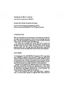
OBJECTIVES The overall objective is to develop simulation technology which enables the flexible access to simulation models having the appropriate resolution depending on the questions asked by the different users. The results should meet the requirements of the turbine design, the virtual testing of new concepts, the development of subsystems like gear boxes or driving systems, the control system design and finally the standard load calculation. As the basis of the developed system works the general purpose MBS simulation tool alaska, which besides the wind force computation provides interfaces to common tools for control system design as well as add-ons for detailed modeling of drive trains and flexible components. The technology of application should be adapted as close as possible to the needs of the standard load calculation. Validated models, parameters and load assumptions which are available for the load calculation should be available to all other users without any conversion. A second objective of the presented approach is to achieve a good separation between the environments for the development of models and their utilization. The following figure shows these two separated processes which are only connected by a common data base.
The database shown in the center of figure 1 is the link between the development and the utilization of the models. It contains model descriptions of subsystems, like e.g. gear boxes, fast shafts, blades and parameter sets for different versions of these models. The development of models provides model descriptions and parameter sets, whereas the utilization of the models only requires access to the parameter sets. In addition, the data base contains descriptions of tested load cases and corresponding files, like e.g. turbulence files and descriptions of transient wind. DEVELOPMENT VS. APPLICATION OF MODELS The development and testing of models and load cases require the application of the modeling system and of the model libraries of the general purpose MBS tool, where the main focus lies on the comfortable debugging features for models of the entire turbine including the control system. To this end a module to compute wind forces according to the current state of the art as well as appropriate components to model load cases that are conform to regulation standards are seamlessly integrated into the modeling system of alaska. In the developed technology, setting up models always means to create models of subsystems. This gives the possibility to create models of the entire turbine simply by combining models of subsystems. There is framework that allows describing the general topology of the turbine. For a certain type of turbine this framework provides a template for each subsystem, which serves as the basis to develop models of different resolution for this subsystem. The template contains the model components which are necessary to ensure the turbine topology and to define correct initial conditions for the component. As an example, for the currently used standard topology, there are templates for the blades, the pitch system, hub, main shaft, gear box, fast shaft, nacelle, and control system.
Figure 1. Application Technology of the Developed System
2
Copyright © 2012 by ASME
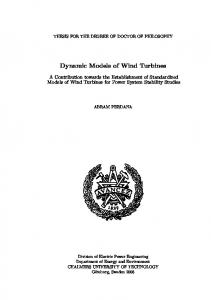
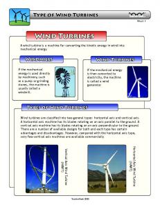
The upper part of figure 2 schematically shows the development of gear box models having different resolution. Starting point is the gear box template of the turbine framework. As an example, a very simple model consisting only of spring and damping constant, ratio and efficiency is available. From this starting point, the different gear box models are developed. These models can then be integrated into each turbine model basing on the same framework without further changes. Thereby, model description and parameters are stored in separate files, where the parameter file contains a reference to the corresponding model description. E. g. to model a 50Hz or 60Hz gear box of the same resolution requires one model file and two parameter files containing the parameters realizing the different ratios. Both, model description and parameter files are components of the data base shown in figure 1. The lower part of figure 2 shows the utilization of the developed models by means of the workbench alaska/wind. This tool is especially designed for that purpose and performs typical tasks for the utilization of predefined subsystems, like e.g. the assembly of turbine models, the generation of blade and tower subsystems, and the administration of load cases. Moreover, single load cases can be simulated in batch mode. Figure 3 gives an impression of the user interface of the work bench to combine models of subsystems to models of the entire turbine. The figure shows the predefined structure of the turbine model, given by the template of the framework and the possibility to select the desired subsystem model by giving a name of a parameter file in the xml-format. At the same time, this part of the user interface supports the change of parameters of the subsystems.
INTERFACES In order to achieve a good integration of the general MBS code into the existing processes of turbine simulation, the developed system supports some common interfaces. Descriptions of the blade geometry as well as of the aerodynamic properties and descriptions of towers can be processed and request files of alaska can be converted into the format of FlexView in order to obtain compatibility to existing post processing tool chains. Another important interface of a tool for turbine simulation is the interface between turbine model and control system. Generally, this interface can be freely configured using the modeling system of alaska. As a standard feature of the MBS tool there are some possibilities to connect the mechanical model with the tool Matlab/Simulink, which is mainly used for control system design.
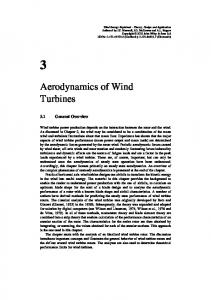
VALIDATION OF MODELS The validation consists of two separate tasks: the experimental validation of subsystem models and the validation of the module for the computation of wind forces in comparison to the results of approved software. For the validation of subsystems experimental investigations of a gear box on a test rig consisting of two equal planetary gear boxes coupled back to back (figure 4) have been carried out and parameters like e.g. the damping were determined. The needed models of the test rig can be efficiently created using the developed technology of combining models from existing models of subsystems. The technology of defining load cases can be applied analogously to the load case processing of turbines. The computed wind forces were validated in comparison to GH Bladed, FAST and Flex5. A large number of significant load cases for the validation of single effects were tested. The validation showed good
Figure 3. User Interface of the Workbench for the Modeling of Turbines Figure 2. Process of Development and Utilization of Models
agreement of the results for conditions, where the theoretical
3
Copyright © 2012 by ASME
CONCLUSIONS The paper describes a technology which enables a smooth integration of a general purpose MBS tool into existing processes of the load simulation of wind turbines. The technology comprises the extension of the MBS tool by the computation of wind forces and the modeling of load cases, a framework for the modeling of subsystems in different resolution and the assembly of this subsystems to models of the entire turbine and a special tool for the utilization of subsystem models without the user interface of the general MBS Tool.
Figure 4. Simulation Model of the Gear Box Test Rig
assumptions of the basic aerodynamic algorithms are valid. Differences at high induction factors and for unsteady conditions can be explained by the different approaches used to treat cases which are not covered by the original theory but may occur at certain load cases.
ACKNOWLEDGMENTS This work was supported by the Federal Ministry for the Environment, Nature Conservation and Nuclear Safety under AZ 0327681. REFERENCES 1. http://www.ifm-chemnitz.de 2. www.garradhassan.com 3. http://wind.nrel.gov/designcodes/simulators/fast/ 4. www.simpack.com
4
Copyright © 2012 by ASME


![Cost of wind turbines [PDF]](https://m.moam.info/img/260x300/cost-of-wind-turbines-pdf_647d40d2098a9edb6d8b4576.jpg)