Efficient Stimulus Generation for Testing Embedded Distributed Systems – The FlexRay Example Eric Armengaud, Andreas Steininger University of Technology Vienna Embedded Computing Systems Group Treitlsstr. 3, 1040 Vienna, Austria {armengaud, steininger}@ecs.tuwien.ac.at Abstract Embedded electronic communication systems play a vital role in the future development of automotive systems. For successful application developments new test and diagnosis solutions for these distributed systems are required. This paper presents solutions for the stimulus generation of test systems based on a remote test under the stringent constraints of the automotive industry. We elaborate a flexible and accurate method that enables a systematic and comprehensive test of data link layer related communication services. Furthermore, we discuss how this solution can be applied for various different test purposes (e.g. for verification, robustness, interoperability or maintenance tests) and demonstrate its application by use of an example that varies one fundamental protocol parameter of FlexRay.
1. Introduction Today’s vehicle networks are transforming automotive control tasks, once the domain of mechanical or hydraulic components, into truly distributed electronic systems. Replacing rigid mechanical components with dynamically configurable electronic elements triggers an almost organic, system wide level of integration. As a result, the cost of advanced systems should plummet. Sophisticated features such as chassis control and smart sensors, now confined to luxury vehicles, will likely become mainstream. All these functionalities translate into higher performance, reliability and maintainability requirements for future automotive systems. Suitable solutions must be developed under stringent cost constraints and provide the modularity to allow the interchangeable use of components from different vendors. With more than 50 distributed electronic control units and applications requiring frequent exchange of information even today’s cars have already become complex distributed systems. Herein, the data networks are an important enabler for future technologies. Time-triggered
Martin Horauer University of Applied Sciences Technikum Wien H¨ochst¨adtplatz 5, 1200 Vienna, Austria
[email protected] communication is being regarded as the most capable paradigm for advanced and safety related control applications (“X-by-wire systems”), and it is quite evident that buses with time-triggered operation modes will play a major role in future automotive networks. Against this background an industrial consortium of leading automotive and electronic manufacturers has established a very promising candidate for future automotive communication systems termed FlexRay, cf. [1]. Relying on both the time- and event-triggered paradigms, FlexRay promises reliability and fault-tolerance aspects with the bandwidth to serve the needs of a communication backbone and the flexibility for the coupling of sensor/actuator systems required for future automotive solutions. In this context of safety critical operations where a failure can lead to severe consequences, means for the evaluation of dependability properties are required. Clearly, testing is essential in order to evaluate whether the system is correctly implemented and will react as expected in its future field environment. However, while methods for testing of the computing nodes themselves on the one side and the bus on the other side do exist, a unified, accurate and systematic test approach on the system level is required that does not only consider the function of these singular components in isolation. Experience shows that problems with interaction of “fault-free” components are becoming increasingly relevant in practice. The problem is further aggravated by the large number of new product variants. It is the aim of our STEACS1 project to address these challenges and take a first step towards a solution. Our goal is to develop a compact method to enable accurate, systematic and comprehensive tests of data link layer related communication services for distributed real time systems based on the FlexRay protocol. In every test approach two fundamental sub-tasks can 1 The
STEACS-project received support from the Austrian “FIT-IT [embedded systems” initiative, funded by the Austrian Ministry for Traffic, Innovation and Technology (BMVIT) and managed by the Austrian Research Promotion Agency (FFG) under grant 807146. See http://embsys.technikum-wien.at/steacs.html for further information.
be identified, namely stimulation of the target and observation of its response. The focus of this paper is on the stimulation aspect, in particular on improving system controllability such that any desired bus traffic can be emulated. A single method is developed that is efficient and flexible enough to be applicable for tests during the different stages within the product life cycle. This aids in amortizing the efforts for the test infrastructure. The next section gives an overview of common test goals and test methods. In Section 3 we summarize related work, before we present our system setup and approach to stimulus generation in Section 4. After a discussion of the applicability of our approach for various test purposes in Section 5 we detail an experiment in Section 6 that we conducted with a FlexRay demonstrator system in order to illustrate the benefits and usefulness of this method. Section 7 concludes the paper.
2. Aims of Testing According to [7], “testing is any activity aimed at evaluating an attribute or capability of a program or system and determining that it meets its required results”. This common definition can be applied to testing of distributed automotive real-time systems with different goals in mind (we assume that every single node has passed its node test): • Verification is a common test procedure during system development that involves checks whether the system adheres to given properties [5]. It aims at revealing implementation faults. Typically, only models or early prototypes of the system are available, and the tests are focused to the investigation of a few mechanisms at a time. Thus, the emphasis for the test environment is set on flexibility. • Conformance testing represents the process of evaluating whether the parameters of an implemented system conform to a specification or a standard; in our case the FlexRay protocol specification [1]. Herein, correct system operation has to be validated for the entire range of possible inputs and parameters. This test is usually executed with some kind of prototype system. In practice, however, these tests will be restricted to a subset of relevant configurations since an exhaustive test of all possible configurations seems not plausible. • Robustness testing is defined in [9] as the characterization of the system behavior in presence of erroneous and/or stressful input conditions. Ideally, all possible inputs (including illegal ones) should be tested; again, however, only a subset will be feasible in practice. Therefore, e.g., fault-injection techniques are used to execute and check the implemented error detection and handling mechanisms.
• According to [8], the purpose of interoperability testing is to prove end-to-end functionality between (at least) two communication systems according to the standard(s) on which those systems are based. Typically, nodes from different vendors are integrated into a distributed system in order to test whether these nodes are able to communicate under a set of possible configurations. • Performance testing, or system evaluation, is used to assess the performance of a given system by means of metrics that can be used to compare the different implementations. Its main focus is on measuring the performance of a system for a well defined set of tasks [3], and not to verify or validate a system. In contrast to verification, efforts are set to the standardization of the test procedure and the tests are typically run on an early product implementation. • Finally, the goal of maintenance testing is to detect and localize faults that emerge during the mission phase of a system. The scope is typically narrowed to (physical) faults that occurred since the last maintenance actions (e.g., due to ageing effects) [5]. In practice, e.g., some kind of tester node is coupled to the system-under-test as illustrated in Figure 1 and a set of tests are executed in order to unveil defective components. Verification, conformance, interoperability, and maintenance tests are qualitative tests with the purpose to prove whether an assumption is correct or wrong whereas robustness and performance tests are quantitative tests that aim at deriving a numerical characterization for a given attribute. Our aim is to develop a single method to enable accurate, systematic and comprehensive tests of FlexRay communication services that, in principle, can handle all of the above tests.
3. Related Work A typical test procedure involves the application of (a sequence of) stimuli – in order to move the system to the desired state – and the observation of the subsequent system reaction. Mainly, for verification, performance, and maintenance testing a correct stimulus in both the value and the time domain is required. In this context we have to deal not only with testing but also with debugging of distributed real-time systems. The observational requirements for these mechanisms differ in the amount and type of information required. Testing is used for unveiling failures (a mainly automated task) whereas debugging is used for identifying the errors that cause the failures (essentially an interactive task). For either purpose we need some facilities to monitor the events emanating from the distributed nodes along with their temporal relation. Furthermore, for
debugging it must be possible to reproduce a situation that led to a failure. In this context a mechanism for deterministic distributed replay of a previously traced or artificially generated behavior is required. State-of-the-art methods that rely on an instrumented kernel to on-line record the timings and occurrences of major system events and a way to off-line replay the recorded events have been presented in [10] and [11]. Conformance and interoperability testing requires that the stimuli can be “tuned” in both the value and the time domain to test the range of valid parameters and configuration constraints. Again a way to monitor and replay the activities of the distributed real-time system is required. To accommodate for the tuning an alteration of the recorded data in both domains must be possible prior to replay, see [8] for some recent advances. The same requirement applies to robustness testing, since it must be possible to create stress conditions for the system. In addition, some types of tests – such as robustness testing, e.g. – involve activating error detection and handling mechanisms. Given that during normal operation fault occurrence is (fortunately) too rare to obtain meaningful results within a reasonable observation time, the artificial insertion of faults and/or errors into a system (“fault injection”) has become popular. The various fault injection techniques and tools, that have been introduced over the years, can generally be divided into simulation based, software based, hardware based and hybrid fault injection, see [6] for a compilation of recent papers. In contrast to these systems our approach aims at an efficient stimulus generation in general generating both valid and (optional) faulty stimuli, respectively. The complexity of our system under test in conjunction with the desired long observation time rules out simulation based approaches. Software implemented fault injection, on the other hand, would require us to install and control some kind of “saboteur” processes on all target nodes – a highly intrusive procedure. Finally, the traditional hardware fault injection techniques requires direct access to the target nodes that is ruled out by our system setup, cf. section 4. Moreover controllability of most traditional methods (pin-level fault injection, heavy ion radiation, etc.) is too low. So obviously none of the existing fault injection methods actually suits our purpose without modification. For laboratory use some kind of general purpose programmable pattern generation and analysis tool could be used to facilitate all the above tests. In practice, however, the usage of such devices is often ruled out since a simple rugged tester implementation for field operation is required and such systems are too complex to handle due to their general purpose design.
4. Stimulus Generation for Testing FlexRaybased Systems This section presents our system setup and discusses different ways how to generate and/or alter the bus traffic, how the fault space can be structured and provides some insights to the architecture of our tester node. 4.1 System Setup For test purposes access to the system under test is needed, and in general the ability to freely access all desired points in a system is decisive for its testability. However, in practice it is impractical to directly access signals on every single node and provide some means to correlate the measurements. Instead, the communication subsystem that is dedicated to facilitating information exchange among all independent physical entities (nodes) suggests itself as the central test access point. Consequently we have chosen the setup illustrated in Figure 1 for our approach: A dedicated remote tester node is connected to the communication bus where it can both, apply stimuli and observe the system reaction. Although this approach is very effective and applicable throughout all phases in the life cycle (access to the communication bus should be available even during maintenance), there are still some restrictions such as, e.g. the distinction of node reactions that have identical (or no) manifestation on the communication bus. Our goal is to exploit the capabilities of this setup as far as possible; in particular we will consider the stimulation aspect in the following. Node A
Node B
Node C
Node D Tester Node X
Star 1
Star 2
Node Y
Node Z
can emulate an entire Sub-Net
Figure 1. System setup Part of the FlexRay protocol is built upon a Time Division Multiple Access (TDMA) principle, which means that a node is allowed to broadcast a frame within a previously defined time window (slot). This allows for three options to physically interfere with the ongoing bus traffic: 1. Physically override regular traffic. The fact that we cannot override a dominant bus state with a recessive one severely limits the capabilities of this method. 2. Use available communication bandwidth to accommodate the stimuli. Considering that the bus schedule is normally very tight, it is optimistic to assume availability of all static and dynamic slots required for testing (changing the bus schedule for the purpose of testing is viewed as a prohibitively intrusive
action). Moreover, this ”addition” of traffic does not allow for the desired change of the regular traffic. 3. Replace part of the regular traffic by tester-generated traffic. This method may either be implemented by (a) physically removing nodes from the system whose behavior is then emulated by the tester node or (b) dividing the system into two subsystems with the tester acting as a bridge between them that modifies the traffic appropriately. Notice that (a) can be viewed as a variant of (b) in which one subsystem is emulated by the tester. We have decided to use method (3) for our purpose, although, it is still intrusive in some sense namely with respect to the physical arrangement of the system. Its main advantage, however, is to give us full control over the bus traffic, thus allowing a large range of target faults or their manifestations, respectively, to be injected. Faults that have no manifestation in the bus traffic are definitely local faults and hence not the target of our test. 4.2. Structuring the Fault Space There are two key ideas involved in our approach for structuring the fault space (A more detailed discussion on this can be found in [4]): • Rather than dividing the system into physical regions – as it is often done in traditional test approaches – we use vertical structuring into layers. This reflects the nature of a distributed system: A service may be spread over several physical nodes. Moreover, with a clever decomposition into independent services located on different layers we can assume lower layers to be transparent for faults that occur on higher layers, which allows us to target faults to every desired service on one or several nodes under test by means of our remote tester. • We describe each service by a set of parameters, which allows us to map every type of failure of this service to one or more parameter faults. Due to the high controllability given by our method – our tester is able to act as an entire sub-net – we are able to produce (generate and/or modify) almost any kind of bus traffic and more especially a stimulus that will render all lower services transparent, allowing us to focus the test on specific mechanisms. Thus, we are able to systematically step through the fault space service by service and parameter by parameter in an automated way. Given the implied independence of the considered mechanisms, single physical defects or local disturbances are likely to affect a single mechanism only (i.e. due to their locality) and hence subclasses thereof can be well represented as single parameter faults. This allows us a systematic treatment of fault causes. On the system level it should be feasible to provoke all possible failure modes of a fault
containment region (=node) by means of single parameter faults (or simple combinations thereof), which allows a systematic treatment on this level as well. In summary, this structuring is a notable achievement since a systematic or even exhaustive coverage of the the fault space based on a less strategic permutation of the bits within the bus traffic alone is hopeless. 4.3. Stimulus Generation/Modification Obviously the most realistic way to alter services within a system implementation is achieved by physical nodes that directly exhibit the hypothesized behavior/defect. However, this solution is very expensive, inflexible and inefficient for an exhaustive exploration of the fault area. An alternative approach uses an emulation of the faulty nodes that generates the same, however, controllable bus traffic as generated by erroneous nodes. Therefore, a complete and accurate model of the emulated nodes/system including the fault model is required in order to attain coherent and realistic results. Four different variants to conceive the emulation of the faulty nodes can be implemented: Online Generation: The tester node executes the emulation of the faulty nodes in real-time. This variant requires substantial processing performance and is mainly required when a direct interaction with the rest of the cluster is mandatory (e.g. to test the clock synchronization, the system start-up or node integration when only a few nodes but no “running” cluster is at hand). Offline Generation: Using this approach, the entire stimulus is pre-processed and stored in an “image” of the bus traffic. The latter is succinctly replayed using a dedicated tester node. This variant suits best when no direct interaction with other nodes is required and no running cluster is at hand, e.g. for verification purposes early in the system design process. Online Modification: When a cluster is available and already operating some faulty nodes can be emulated by generating the respective bus traffic. Herein, the tester must be able to alter/override orderly traffic emanating from other, remote nodes in order to emulate the intended faulty behavior. Instead of generating the entire traffic for a set of nodes this variant concentrates on the alteration of existing traffic. The difficulties lie in the triggering of these fault injections and the alteration of the bus traffic (e.g. the tester could split the network by acting as a kind of gateway, modify the traffic emanating from one subnet and replaying the modified bus traffic to the other one). Furthermore, the delay originating from the processing time of the tester node must be accommodated in some way. Offline Modification: Using this variant, the bus traffic of a “running” cluster is recorded by the tester; an im-
age is off-loaded to a remote processing host where it is altered. The modified image is then copied back to a tester that transforms it into a bus traffic. The challenge herein lies in controlling the remote “properly behaving” nodes during replay in order to reenact the same scenario as encountered during the monitoring process. Thus, this method best suits test situations where the majority of nodes is under control of the tester. As with the offline generation approach, this variant is practical for systems requiring only limited interactivity with the system under test. The main differences between the online and the offline methods are the performance requirements of the tester node and the interaction with the test engineer to control the test and debug process. The offline methods relax the performance requirements at the tester node since the bus traffic to be inserted by the tester is created at a host without real-time constraints. In case of modification this means that data is monitored for a fixed amount of time, off-loaded to a host, presented to the test engineer and post-processed. The latter involves extracting and modifying those portions of the image that correspond to traffic generated by the nodes to be emulated. Next this so modified data is copied back to the tester and replayed to the system under test. The online methods, in contrast, process and alter the data of the emulated nodes in real-time. In order to keep the delay caused by the processing of the emulated mechanisms low, substantial processing performance and suitable optimizations are required at the tester. The main difference between generation and modification methods lies in the source of the “regular” bus traffic: Modification methods use existing regular traffic, thus reducing the modelling efforts to the actual alteration. This approach implicitly reflects implementation details of the system under test (which is the origin of the regular traffic) and therefore creates a very realistic and representative traffic. Generation methods, in contrast, require a complete model including the regular behavior. Their strength is to provide a “perfect”, specification conform traffic without being influenced by implementation details of the considered system. 4.4. Tester Node Architecture All variants of the previously discussed approaches can be implemented within one single, dedicated tester node. Figure 2 illustrates the resulting architecture with four different paths for the stimuli. The tester is built upon a standard protocol engine enhanced by the ability to access and therefore modify data on different layers according to a fine grained layer model, cf. [4]. The common characteristics of the online methods is to compute the bus traffic modifications directly on the tester node. On the contrary, off-line methods employ external data manipulation resources to alter (and possibly generate) the bus traffic. To that aim, the tester node can be equipped with observation points and control points to increase the system testability and provide by-passes to the
“normal” processing path. Ideally, for the offline modification approach the bus traffic is received, from an observation point in a representation just on the very layer the service under consideration is located at and passed onwards to the modification unit. The latter alters the information as required and feeds it back down onto the transmission path using a control point right below the layer of the considered service. In practice, the position of control and observation points is implementation dependent and not dense (i.e., in practice not every layer needs to be equipped with a control point and an observation point). Consequently, additional simulation for the neighboring layers might be required to adjust the abstraction level of the data (1) between the observation point and the level on which it is to be modified and (2) between there and the next control point where the data can be re-injected within the tester node (cf. Figure 2 for the offline modification method. For the other methods this procedure is essentially the same with the difference that for generation methods no observation is required, of course.). Finally, a fault library is required to control the process of fault injection. In particular, information is required where the fault shall be injected, what kind of fault model shall be used, and when the fault shall be activated (i.e. a trigger condition). In our case, the fault library is focused to the tester node’s transmit path. Indeed, the deviations are aimed to be injected on the communication medium solely, hence, the receive path of the tester is not our main focus since it provides only very limited influence onto the system under test (e.g. via the clock synchronization).
5. Application of the Stimulus Generation Methods The different stimulus generation/modification methods are applicable to the different tests listed in Sec. 2. The following list highlights the methods better suited for the various test scenarios: • An image of a generated bus traffic can be used to derive stimulus for simulation based methods for verification purposes in an early design stage when a new distributed application is being developed and no system prototype or cluster is at hand. In practice, some means will be required to convert the generated bus traffic to a format that can be interpreted by the particular target simulator in use. Instead of bus traffic generation, a similar cluster equipped with our tester node could be re-used to record the bus traffic that can be fed to the simulator as well. • When a prototype of one node is available our tester node can be configured to employ a generation method in order to emulate an entire network, thus, easing system development. For debugging purposes the offline variant is more attractive since the developer has better and direct control of the generated stimuli. In contrast, the online variant is preferable
Software (off-line mode only) Data manipulation tool
Hardware tester Receive path
Hardware
Transmit path
OP(i+3)
Fault library
Transmit path CP(j+2)
tester
OP(i+2) Host System Controller Host Interface CP(j+1)
Protocol engine Bus Driver
Bus Driver
OP(i+1) OP(i)
CP(j)
OP: Observation Point
offline modification variant
online modification variant
CP: Control Point
offline generation variant
online generation variant
Figure 2. Stimulus generation methods
for testing in order to verify specific functionalities in an automated manner. • Later on in the development phase, generation methods and herein the offline variant in particular using standard “images” is useful for conformance testing to test whether the developed application acts conform to the standard. • For robustness tests the availability of an entire cluster is advantageous. A tester attached to the network of this cluster using the modification method is able to disrupt the bus traffic by way of fault injection (Online modification is preferable here due to its low intrusiveness). Hence, using this approach one can efficiently test the fault tolerance mechanisms of the communication subsystem. • For interoperability tests, generation methods are useful when only one node is available. The tester can emulate an entire network using traffic patterns recorded in conjunction with other nodes. Hence, one can easily evaluate whether the nodes will be able to communicate with each other using the various different, tested configurations. • Likewise, generation methods are useful for performance evaluation. A pre-defined, standard set of stimuli can be applied to different systems in order to derive characteristic measures. • Finally, the online variants can be used to test a system put into service. Then offline variants are useful to debug the system in order to help for an identification of certain faulty behaviors.
Summarizing, generation methods are more useful when no entire cluster is available otherwise modification methods can be used as well. Offline methods on one hand are better suited for situations where the developer needs to interact and directly control the system under test, e.g. for debugging purposes. Online methods on the other hand are preferable for automatic tests. Our approach is flexible enough to support all four methods.
6. Experimental Assessment The aim of the subsequent experiment is to explore the controllability and execution time of the off-line modification method. The test object is a distributed application based on FlexRay [1]. As already mentioned this communication protocol partially relies on a Time Division Multiple Access (TDMA) principle, which means that a node is only allowed to send a frame within a previously defined time window (slot). 40 cm Node A Node B (replay) (short)
120 cm Node C (long)
Communication slot N Frame ID N Action Point
t
Figure 3. Experiment setup
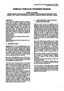
100,00% 90,00% 80,00% fault rate (%)
70,00% 60,00% 50,00% 40,00% 30,00% 20,00% 10,00%
...
60 0 10 00 14 00 18 00 21 25 21 75 22 25 22 75 23 25 23 75 24 25 24 75 25 25 25 75 26 25 26 75 27 25 27 75 28 25 28 75
-1 75 0 -1 70 0 -1 65 0 -1 60 0 -1 55 0 -1 50 0 -1 45 0 -1 40 0 -1 35 0 -1 30 0 -1 25 0 -1 20 0 -1 15 0 -1 10 0 -1 05 0 -1 00 0 -6 00 -2 00 20 0
0,00%
offset(ns) Node B
Node C
Figure 4. Results of the fault injection
The following, experimental campaign consisted of shifting the “action point” of a frame – i.e., the point in time when transmission of this frame is started – in a way so that the frame moves close to/beyond its associated slot boundary. The aim was to create a slightlyoff-specification2 failure [2] and observe the rate of faulty frames at different points of the communication medium and with different hardware implementations (physical layer chips from different vendors). This experiment could be used, e.g., to assess robustness properties when one node violates its pre-defined transmission slot or for interoperability tests to evaluate the range of allowed shifts within one slot. Before the campaign start, 35 seconds of bus traffic generated by a FlexRay based application have been (physically) traced. The bus traffic consisted of 2.223 communication cycles, each composed of 336 slots/frames. Within this image 62 of these frames were shifted; in particular negative offsets – i.e. when the frame started too early – in a range from −1750ns to −1000ns and positive offsets – i.e. when frame started too late – between +2125 and +2875ns were applied with a granularity of 25ns that was determined by the 40M Hz system clock of our tester node implementation. This procedure was repeated for all communication cycles, which accounts for a total of 137.826 modifications. Finally, the modified bus traffic was replayed to the communication medium. Figure 3 illustrates the experiment setup. The modified bus traffic has been replayed by node A to the other nodes B and C placed at a distance of 40 and 120cm from node A, respectively. During this campaign node A replayed the entire bus traffic and therefore emulated the FlexRay application at the communication medium interface for node B and C. The experimental results are quite interesting: Node C regarded messages with an offset range between −1100ns 2 An example for a slightly-off-specification failure is when a node sends on its slot boundaries in such a manner that it is accepted as temporal accurate by a subset of nodes whereas it is not accepted by a different subset of nodes, hence, causing asymmetry in the system.
and +2475ns as correct. This attests a quite high robustness of the protocol with respect to the frame offset. Beyond this 3.5µs range there is a quite steep slope from 0 to 100 percent error rate (see Figure 4): Approximately 200ns in the negative direction and 250ns in the positive direction. This observation, and more generally the ability to perform this type of measurement with a suitable accuracy and within reasonable time is a first confirmation of the practical usefulness of our concept. Node B showed a significantly different behavior: Offsets in the range between −1525ns and +2250ns were tolerated. As Figure 4 illustrates, this means that in comparison to node C the tolerance window of node B is broader and oriented more towards negative offsets. This observation allows another important conclusion: There is definitely a non-zero probability that slightly-offspecification failures may cause Byzantine effects in the network: The same frame has been regarded as correct by node C and as erroneous by B. In order to evaluate whether the node’s position in the network is decisive for this different perception, we simply exchanged nodes B and C and repeated the experiment campaign. The results (not shown) were nearly the same, which clearly indicated that the position has only a minor influence, and that the differences observed in Figure 4 are therefore mainly due to the different physical layer chip implementations (Considering that the signals require only 5ns to travel 1m on the communication medium, this was essentially no surprise). This allows a further important conclusion: The potential for Byzantine effects is significantly higher when different hardware implementations are interoperating. This simple experiment illustrated some important benefits of our test pattern generation method: (1) The controllability is sufficient for exploring temporal protocol/implementation boundaries with suitable resolution. (2) The test on a prototype boosts test execution: Indeed, the monitoring of the FlexRay application required 35 seconds once, and then approximately 38 seconds were sufficient (i) to shift the 137.826 frames in the image in a
fully automated way, and (ii) to replay the modified image and monitor the bus traffic. This allowed us to complete one systematic experimental campaign within 2 minutes, based on a total of 137.826 samples. (3) Recording the bus traffic pattern from a cluster executing an actual workload guarantees a representative and realistic scenario. In the same way the system reaction is actually observed in a physical implementation, which not only guarantees that the observed effects are relevant in practice, but moreover allows to associate the observation with a given implementation.
7. Conclusion Testing of distributed embedded automotive communication systems gains momentum since electronic components absorb more and more functionalities. Herein, one fundamental process that is repeated for all kinds of tests is the generation of stimuli. To that end, we proposed in this paper methods and an architecture tailored for stimulus generation that can be used to test communication subsystem related functionalities of distributed automotive applications. In particular, a dedicated remote tester may emulate the behavior of one node or an entire sub-net (including nodes with faulty behavior) and, hence, provides an elegant way to enhance the controllability required for testing such systems. Our experimental example has illustrated that the controllability attained by this remote approach is sufficient for a boundary test of protocol parameters and allows a very systematic and fully automated test procedure, yielding a significant number of samples within reasonable time. The presented approach can be re-used for many different purposes, e.g. for debugging and testing during system verification, for interoperability or robustness tests as well as even for maintenance tests. In addition, the same tester can be used for monitoring the bus traffic. Finally, the combination of stimulus generation and monitoring may be extended to enable remote fault diagnosis and fault localization.
References [1] Flexray Communications Systems - Protocol Specification Version 2.0. FlexRay Consortium, 2004. [2] A. Ademaj. Slightly-Off-Specification Failures in the Time-Triggered Architecture. Seventh Annual IEEE International Workshop on High Level Design Validation and Test , October, 2002, Cannes, France, pages 7–12, Oct. 2002. [3] J. Arlat, K. Kanoun, H. Madeira, J. Busquests, T. Jarboui, A. Johansson, and R. Linstr¨om. State of the Art. DBench project deliverables, Aug. 2001. [4] E. Armengaud, A. Steininger, M. Horauer, and R. Pallierer. A Layer Model for the Systematic Test of TimeTriggered Automotive Communication Systems. 5th IEEE International Workshop on Factory Communication Systems, pages 275–283, September 2004.
[5] A. Avizienis, J.-C. Laprie, B. Randell, and C. Landwehr. Basic Concepts and Taxonomy of Dependable and Secure Computing. IEEE Transactions on Dependable and Secure Computing, 1:11–33, Jan.-Mar. 2004. [6] A. Benso and P. Prinetto. Fault Injection Techniques and Tools for Embedded Systems Reliability Evaluation. Kluwer Academic, 2003. [7] W. Hetzel. The Complete Guide to Software Testing, Second Edition. Wiley, 1988. [8] S. Mosely, S. Randall, and A. Wiles. Experience within ETSI of the Combined Roles of Conformance Testing and Interoperability Testing. The 3rd Conference on Standardization and Innovation in Information Technology, pages 177–189, Oct 2003. [9] A. Mukherjee and D. P. Siewiorek. Measuring software dependability by robustness benchmarking. IEEE Transactions on Software Engineering, 23(6):366–378, June 1997. [10] D. Sundmark, H. Thane, J. Huselius, and A. Pettersson. Replay Debugging of Complex Real-Time Systems: Experiences from Two Industrial Case Studies. Proceedings of the 5th International Workshop on Algorithmic and Automated Debugging, pages 211–222, September 2003. [11] H. Thane, D. Sundmark, J. Huselius, and A. Pettersson. Replay Debugging of Real-Time Systems Using Time Machines. In Proceedings of Parallel and Distributed Systems: Testing and Debugging (ACM), pages 288–295, April 2003.