Aswan Faculty of Engineering, South Valley University. 81542 ASWAN, Egypt .... distribution feeder can modelled as wye-connected or delta- connected.
Efficient Three-Phase Power-Flow Method for Unbalanced Radial Distribution Systems Karar Mahmoud and Mamdouh Abdel-Akher APEARC, Department of Electrical Engineering Aswan Faculty of Engineering, South Valley University 81542 ASWAN, Egypt
Abstract—this paper presents an efficient three-phase power flow algorithm for distribution network analysis. A new transformer model with various connections is implemented in the forward/backward sweep power flow method. The developed method provides an effective solution to the singularity problem of the nodal admittance submatrices appeared in some transformer configurations. Different load models and capacitor banks are also implemented with any number of phases and any connection. The proposed load flow has been tested using both the IEEE 4 and 34 node test feeders. The obtained results show that the proposed load flow is very efficient and the numerical solution is identical to that provided with the IEEE data. Keywords: Radial load-flow, transformer model, backward/forward methods, sequence components, phase component, distribution systems.
I. INTRODUCTION Efficient power flows algorithms are needed in order to analyze distribution systems. There are number of methods in the literature for power flow solutions. These methods can be classified to Newton-Raphson, Gauss- Seidel, and Fast Decoupled algorithms [1-3]. These classical methods may become inefficient in the analysis of distribution systems which is characterized by high R/X ratios or special network structures [4]. Consequently, there are power-flow methods which have been designed for the solution of power flow problem considering the distribution system radial distribution structure. These methods include the Newton Raphson-based methods [4-6] and the backward/forward method [7-9]. It is well known that very good results are obtained using the backward/forward procedure. This method is easy to implement, and able to take full advantage of the radial structure of distribution systems. The method also has superior performance characteristics and easy implementation of neutral wire and ground return [8]. Experiences demonstrate that implementation of distribution transformer in the backward/forward method has a singularity problem of the nodal admittance sub matrices. This causes by the lost of ground reference on the ungrounded transformer sides. Several approaches have been developed in the literature. In Ref [9], the coupling between the primary and secondary sides is converted to equivalent current injection sources, thus transformer admittance is similar to ordinary line model. However, when this model is
978-1-4244-5795-3/10/$26.00 ©2010 IEEE
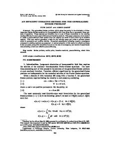
implemented in forward backward sweep algorithm; it will be unsatisfactory due to relatively slow convergence problems. Other approach is based on sequence components for modelling the transformer [10]. In this method, transformation of variables from phase to sequence and vise versa is required at the transformer terminals. In this paper, a generalized transformer model is derived from an improved sequence component model [12]. However, the final model is expressed in phase component after isolating the zero-sequence component. The model is incorporated in the forward/backward sweep method for all various transformer connections. The model is tested using the IEEE test feeders with different loading conditions. The results illustrate that the proposed transformer model are reliable and has good convergence characteristics. This paper consists of the following sections. In Section II, Distribution components modelling including line and load modelling are presented for unbalanced distribution system. In section III, the power flow algorithm is obviously explained. In section IV, a new three transformer model is driven for various connections types and integrated to the power flow algorithm. In Section V, numerical examples using the IEEE test feeders demonstrate the validity and effectiveness of the proposed model. II. DISTRIBUTION SYSTEM MODELLING The detailed of models for distribution system elements include: A. Line mode Distribution lines employ phase coordinates for the solution of the unbalanced distribution systems. Fig. 1 shows the line model which can be represented by a 3×3 impedance matrix as in [8].
Zline
zaa zba = z ca zna
zab zbb zcb znb
zac zbc zcc znc
zan zbn zcn znn
(1)
The classical three-phase power-flow analysis adopted only three phase representation of line matrix. This is obtained by applying Kron’s reduction technique. This technique merges
125
I
I
j _ abc ←
i _ abc →
Z Vi _ abc
S Yabc 2
vsa vsb vsc
vap
abc line
vbp S Yabc 2
vcp
Vj _abc
Fig. 1 Model of the three-phase four-wire multi grounded distribution Fig.2 Generalized Distribution Transformer Model.
the effect of the neutral wire into the three wire wires. This is applicable for well-grounded distribution system [6-8].After Kron’s reduction; the line matrix is reduced to an equivalent 3×3 matrix as follows:
(2)
If any phase, neutral wire, or grounding of the line section does not exist, the corresponding row and column in this matrix contain all zero entries. The shunt admittance of the distribution lines can be neglected specially for short length distribution lines and low voltage levels.
Sia , Sib, Sic Via , Vi b, Vic
B. Backward Sweep This is step aims to update the currents and powers towards the root node. The step is based on the fact that the current is known at the lateral of the feeder, and hence the total current at the source node can be calculated through the backward sweep which aims to sum up line section current starting from last layer towards and moving towards first layer. 1) the current in the line segment l:
B. Load model The loads on a distribution system are typically specified by the complex power consumption. The loads on a distribution feeder can modelled as wye-connected or deltaconnected. In addition, the loads can be three-phase, twoPhase or single-phase [11].
=-
Jna , Jnb, Jnc M
Where: Iia , Iib, Iic
(3)
are the current injections for phases a, b and c at node i ;
k
+ ∑m
M
(4)
are current flows on line section n; is the set of line sections connected downstream to node j;
2) The Powers Entering Line Segments l: for each branch, the entering powers can be calculated by the following equation:
(5)
A. Nodal Current Calculations This is an initial step for the backward/forward algorithm. In this step, load currents are initially calculated by assuming initial voltages for all nodes to be equal to the root node voltage. At iteration k:
⁄ ⁄
k
k
III. GENERALIZED THREE-PHASE POWER-FLOW ANALYSIS The backward/forward methods are adopted in this paper which is suitable for analyzing radial distribution networks. The method is based on backward/forward sweep analysis using Kirchhoff’s voltage and current laws [4]-[13]. With the knowledge of the magnitude and angle of three-phase voltages at root node (substation). An iterative process can be developed for power flow solution. This process includes three main steps as follows:
⁄
are the scheduled power injections for each phase at node i; are the phase voltages at node i;
Where: (6)
C. Forward Sweep The forward step is also called the voltage update step. This step is based on the fact that the voltage at the source node is known. Hence, starting from the first layer and moving towards the last layer, the currents at the sending end of line
126
segment and then the voltages at its receiving end are calculated. 1) Calculate line Currents: the line current for each segment will update by using the entering powers which calculated in backward sweep step as the following: ⁄
Where p and S Y I
v
(7)
⁄
2) Voltage update: the voltages at the receiving end of the line segment are calculated by:
(8)
After the above three steps are executed in one iteration, the power mismatches at each node for all the three phases are calculated as follows:
Y Y
,I
,v
, Y ,Y
,
referring to the primary and the secondary sides. represent the transformer nodal admittance matrix. are the injection currents at the primary and the secondary side respectively. line-to-neutral bus voltages at the primary and the secondary side respectively. represent the (3×3) submatrices of the nodal admittance matrix of the transformer.
The elements of the (6×6) nodal admittance matrix will mainly depend on the connection of three phase transformer. The authors of [11][14] present the nodal admittance matrices for various common connections of three-phase transformers. The resulting (6×6) sequence admittance matrix is used for constructing the sequence component transformer model which used for building the decoupled sequence admittance matrices as following: (11)
= Where:
(9)
(12)
If the real or imaginary part (real or reactive power) of any of these power mismatches is greater than a convergence criterion, steps A, B and C are repeated until convergence is achieved. The developed algorithm can solve systems with any number of phases. Therefore, the developed power algorithm in this paper is generalized. IV. INTEGRATE THREE-PHASE TRANSFORMER MODEL In this section, a new method is proposed to model the distribution transformers into the forward/backward sweep load flow algorithm. The nodal admittance matrix is used in sequence components model. However, instead of transforming the sub-matrices of the phase coordinates model [11], the full matrix of the phase coordinates transformer model is transformed into sequence components [12]. The transformer model is established by transforming the overall transformer admittance matrix in phase components to its counterparts in sequence components as follows: T 0 Y012 node = 0 T Yabc pp Yabc node = abc Ysp 1 T= 1 1
1 t2 t
1 t t2
-1
Yabc node
T 0
0 T
Yabc ps
(10)
(13) (14) A. Positive and negative sequence modelling Then, only positive and negative components of voltages and current are only integrating to the forward/backward sweep method. The zero components of voltages and currents will be separately integrated. The following equations can be written in matrix notation as follows: 1) Bakward sweep equation: From theses last equations the positive and negative sequence current in the primary side can be calculate by: ,
Where:
,
(15) (16)
Then, forward and backward sweep equations are transformer back from sequence component to phase component model as the following:
Yabc ss
̀
̀
and t =1 120
127
̀ ̀
(17) ̀
(18)
TABLE I SUB-MATRICES OF DECOUPLED SEQUENCE NETWORKS FOR STEP DOWN TRANSFORMERS Backward Sweep Submatrices CONNECTION
P&N component
Forward Sweep Submatrices
Zero component
P&N component
Zero component
GY-GY
̀
M1
̀
M1
̀
M1
̀̀
M3
̀
0
̀̀
M3
̀
M3
̀
M1
̀
M1
̀
M3
M3
D-D
M1
M1
M1
0
0
0
0
M1
M1
0
0
̀
Y-D
M2
M2
M2
0
0
0
0
M2T
M1
0
0
GY-Y
M1
M1
M1
0
M3
0
0
M1
M1
0
0
0
M2T
M1
0
0
GY-D
M2
M2
M2
0
M3
0
TABLE II TOTAL SUB-MATRICES OF THE FINAL STEP DOWN TRANSFORMER MODEL IN PHASE COMPONENT COORDINATE Backward Sweep Submatrices
CONNECTION a
b
c
d
C
D
GY-GY
M1+M3
0
M1+M3
M1+M3
M1+M3
M1+M3
D-D
M1
0
M1
M1
M1
M1 M1
Y-D
M2
0
M2
M2
M2T
GY-Y
M1
M3
M1
M1
M1
M1
M2
M2T
M1
GY-D
M2
M3
M2
,
2)
̀
̀
̀
,
̀
(20)
Consequence the phase’s voltage (a, b, c) in the transformer primary side can be easily driven from the positive sequence and negative sequence admittance matrices. Where the value of the submatrices (à , c̀ , d̀ , C̀, D̀) are mainly depending on the connection type of the three-phase transformer. The values for these submatrices are for different connection types are given in Table I. B. Integration of zero sequence components Several things should be pointed out concerning the proposed model. First that the zero component update in forward and backward sweep are not take in the consideration yet. The zero components will add to the equations as following: ̀̀
̀
(21)
̀
̀̀
(22)
2) Forward sweep equation: ̀
(19)
1) Backward sweep equation:
,
√
Forward sweep equation: The positive and negative voltages of the secondary side for the transformer are calculated by:
̀
Forward Sweep Submatrices
̀
̀
(23) Where the value of the submatrices ( à̀ , b̀ , c̀̀ , d̀ , C̀ , D̀ ) are mainly depending on the grounding configuration of the threephase transformer. The grounding configuration can be divided into the following four classes: -
Primary and Secondary both Grounded : Primary and Secondary Both Ungrounded: grounded Primary—Ungrounded Secondary: Ungrounded Primary—grounded Secondary:
For each class, the values of the zero sequence submatrices are similar. The value for these sub matrices for different connections types are given in Table I. C. The final Model This is the final step for the generation of the transformer model. In this step, the final phase component of the currents and voltages are computed by adding the zero components to the positive and negative component as the following:
128
2) Forward sweep equation: ̀
̀
̀
̀
(31) ̀
̀
(32) (33)
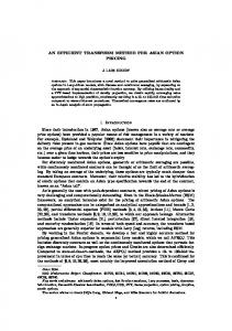
The first two set of equations are used in backward sweep process and the last set of equation is used in forward sweep iteration process. With the above transformation, the equations for transformer voltage calculation are no longer singular. In addition to that, the resulted transformer voltages in the primary and secondary side of the transformer ( V , V ) contain the positive, negative sequence and zero component components. Similar derivation can be made for all various three phase transformer connections. The formulation of the phase coordinates transformer is given in Table II. V. RESULT AND DISCUSSION Two test systems are used to validate the developed powerflow and the corresponding models. Firstly, the IEEE4 node is used to test the transformer model. The performance of the power-flow is tested using the IEEE 34 node feeder. The IEEE 34-bus test example is used to demonstrate the proposed transformer models in large systems (Fig. 4). The base voltage of the feeder is V .9 kV, and the reference voltage in the root node is V . KV . For simplifications, the automatic voltage regulator is also not represented and replaced with a line segment. There are two transformers in this system. One is located between nodes 800 and 802, and the other is between nodes 832 and 888. The solution of the IEEE 4 node feeder is given in Table III, the calculated results is identical to the solution reported with the IEEE test case study. The proposed method is compared with a commercial distribution power-flow utilizes the bus admittance method. All the loads of the IEEE 34 node feeder
Fig. 3 Flow chart of the power flow algorithm.
Fig. 4 The IEEE 34 node test example.
1) Backward sweep equation: ̀
̀̀ ̀
̀ ̀
̀̀
̀
(24) ̀ ̀
̀
(25) (26)
(27) ̀
̀
TABLE III LINE TO LINE VOLTAGES OF BUS ‘4’ FOR THE IEEE 4 NODE TEST FEEDER V4ac V4bc V4ca Type Mag. Ang. Mag. Ang. Mag. Ang. 1.5004 22.7 1.42194 -102.7 1.3438 143.0 GY-GY D-GY
1.4968
-7.3
1.4261
-132.4
1.3485
112.8
GY-D
1.4262
-5.8
1.5181
-130.3
1.3731
108.6
Y-D
1.4262
-5.8
1.5181
-130.3
1.3732
108.6
D-D
1.4284
24.3
1.5187
-100.4
1.3713
138.6
(28) TABLE IV CONVERGENCE CHARACTERISTICS OF THE PROPOSED LOAD FLOW Number of Iterations (IEEE 34 Node Feeder) Load Factor Proposed method Commercial Software 3 5 0.25 0.50 4 9 5 8 0.75
(29)
Equations (26) and (29) are used for Calculation of the power injections on the primary side: (30)
1.0
129
8
12
are converted to by PQ load model type. The loads are then varied as exhibited in Table IV. The number of iterations for the proposed method and the commercial software is then summarized in Table IV. The table shows that the proposed method and the developed transformer model are accurate and have robust convergence characteristics even with feeders with bad convergence characteristics such as the IEEE 34 node feeders. VI. CONCLUSIONS The paper has presented an efficient power flow analysis which utilizes improved transformer model. The load-flow has considered a lot of distribution networks features such unbalanced loads, capacitors banks, and unbalanced lines, and transformer model with any connection. The calculated results show that the proposed model is accurate and robust when it is compared with existing commercial software program. The proposed method is currently being extended for modelling distributed generation resources. ACKNOWLEDGMENT The authors gratefully acknowledge the contribution of the Science and Technology Development Fund (STDF) for providing research funding to the work reported in this paper. REFERENCES [1] W. F. Tinney and C. E. Hart, “Power Flow Solution by Newton’s Method,” IEEE Trans. Power Apparatus and Systems, vol. PAS-86, pp. 1449–1460, 1967. [2] B. Stott and O. Alsac, “Fast Decoupled load-Flow,” IEEE Trans. Power Apparatus and Systems, vol. PAS-93, pp. 859–869, 1974.
[3] Garcia, P.A.N.; Pereira, J.L.R.; Carneiro, S., Jr.; da Costa, V.M.; Martins, N. “Three-phase power flow calculations using the current injection method” Power Systems, IEEE Trans. Volume 15, Issue 2, May 2000 Page(s):508 – 514 [4] G. X. Luo and A. Semlyen, ‘Efficient load flow for large weakly meshed networks’, IEEE Trans. Power Systems, 5 (4) (1990). [5] Jen-HaoTeng; Chuo-Yean Chang “A branch voltage based three phase load flow method for unbalance distribution systems” power System Tec hnology, 2000. Proceedings. Power Con 2000. International Conference on Volume 2, Issue, 2000 Page(s):601 - 606 vol.2 [6] T. H. Chen and W. C. Yang, “Analysis of multigrounded four-wire distribution systems considering the neutral grounding”, IEEE Trans. Power Delivery, 16(4), pp 710-717, October 2001. [7] C. S. Cheng and D. Shirmohammadi, :A three-phase power flow method for real-time distribution system analysis, IEEE Trans. Power Systems, vol. 10, pp. 671–679, May 1995. [8] Rade M. Ciric, Antonio PadilhaFeltrin, and Luis F. Ochoa “Power Flow in Four-Wire Distribution Networks—General approach IEEE trans .power systems, vol. 18, no. 4, November 2003 [9] T. H. Chen, M. S. Chen, T. Inoue, P. Kotas, and E. A. Chebli, “ Three phase cogenerate and transformer models for distribution system analysis,” IEEE Trans. Power Del., vol. 6, no. 4, pp. 1671–1681, Oct. 1991. [10] U. Eminoglu m. H. Hocaoglu “Three-phase transformer modeling for forward/backward sweep-based distribution systems power flow algorithms”, 42nd Universities Power Engineering Conference, UPEC 2007, Brighton, UK, pp. , September 2007 [11] M. S Chen. and W. E.Dillon, Power system modeling ,Proc. IEEE, vol. 62, pp. 901–915, July 1974. [12] M. Abdel-Akher., K. Mohamed Nor., and A. H Abdul Rashid., Improved Three-Phase Power-Flow Methods Using Sequence Components, IEEE Trans. on Power Systems, Vol. 20, No.3, pp.13891397, August 2005. [13] Z. Wang, F. Chen, and J. Li, Implementing transformer nodal admittance matrices into backward/forward sweep-based power flow analysis for unbalanced radial distribution systems, IEEE Trans. Power Systems, vol. 19, no. 4, pp. 1831–1836, Nov. 2004. [14] Xiao Peng, C. Yu David, and Wei Yan “A Unified Three-Phase Transformer Model for Distribution Load Flow Calculations” IEEE Trans. Power Systems, Vol. 21, No. 1, February 2006.
130