diagram, view of participating classes, sequence dia- grams, user interface, business rules, special require- ments and other artifacts. Here, we explain the main ...
Effort Estimation Tool Based on Use Case Points Method
†
Shinji KUSUMOTO† , Fumikazu MATUKAWA† , Katsuro INOUE† , Shigeo HANABUSA‡ , Yuusuke MAEGAWA‡ Graduate School of Information Science and Technology, Osaka University, 1-3, Machikaneyama, Toyonaka, Osaka 560-8531, Japan Tel: +81-6-6850-6573, Fax +81-6-6850-6574 E-mail: {kusumoto, matukawa, inoue}@ist.osaka-u.ac.jp ‡ Hitachi Systems & Services, Ltd.
Abstract Use case point (UCP) method has been proposed to estimate software development effort in early phase of software project and used in a lot of software organizations. Intuitively, UCP is measured by counting the number of actors and transactions included in use case models. Several tools to support calculating UCP have been developed. However, they only extract actors and use cases and the complexity classification of them are conducted manually. We have been introducing UCP method to software projects in Hitachi Systems & Services, Ltd. To effective introduction of UCP method, we have developed an automatic use case measurement tool, called U-EST. This paper describes the idea to automatically classify the complexity of actors and use cases from use case model. We have also applied the U-EST to actual use case models and examined the difference between the value by the tool and one by the specialist. As the results, UCPs measured by the U-EST are similar to ones by the specialist.
1
Introduction
As the role of software in the society becomes larger and more important, it becomes necessary to develop high-quality software cost-effectively within a short period. In order to achieve this goal, the entire software development processes need to be managed based on an effective project plan. It is essential to estimate various undesirable phenomena which happened during the project and take measures to prevent them in advance to construct distinct plan. The subjects of estimation in the area of software development are size, effort invested, development time, technology used and quality. Particularly, development effort is the most important issue. So far, several effort models [4][5][13] have been proposed and most of them include software “size” as an important
parameter. Function point is a measure of software size that uses logical functional terms business owners and users more readily understand [1]. Since it measures the functional requirements, the measured size stays constant despite the programming language, design technology, or development skills involved. Up to the present, various FPA versions based on the Albrecht’s version have been proposed (e.g. IFPUG method[8], MarkII[12], COSMIC-FFP [6]) and they have been accepted as ISO/IEC standards. However, in order to precisely measure function point, it is necessary to use the detailed information about the target software. Such information is defined in the detailed software design specification. On the other hand, software development period for recent software (e.g. Web application and embedded software) becomes too short to spare time to count function point from the detailed design specification. So, it is difficult to apply function point to such software. To estimate the effort in earlier phase, use case point method has been proposed[10]. Use case point (UCP) is measured from a use case model that defines the functional scope of the software system to be developed. It is influenced by the function point methods and is based on analogous use case point. There are several experience reports that show the usefulness of use case point for early estimation of software size. We have been involved in the activity to introduce effort estimation method to Hitachi Systems & Services, Ltd. In the company, the period of software development project is becoming shorter and also a method to estimate the effort in the early phase is expected. This paper describes the actual experience of introducing use case point method to software projects in the company. To effective introduction of use case point method, at first, we develop a use case measurement tool. Since the main activity of calculating UCP
is to classify the complexity of actors and use cases and is conducted manually, we address the automatic classification of them. Then, we apply the tool to actual use case models developed in the company and compare the UCP values calculated by the tool to ones by the specialist. As the results, UCPs measured by the U-EST are similar to ones by the specialist. Section 2 briefly explains use case point method. Next, Section 3 proposes the use case point measurement tool and Section 4 describes the case study. Finally, Section 5 concludes the paper.
2
Order Processing System
Place order
Customer
Return product
Use Case Point Method
This section briefly explains the measurement steps in the use case point method described in [10].
2.1
Use case model
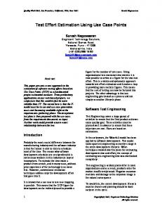
Use case point (UCP) is calculated from use case model[10]. The use case model mainly consists of two documents, system or subsystem documents and use case documents that include the following items: system name, risk factors, system-level use case diagram, architecture diagram, subsystem descriptions, use case name, brief description, context diagram, preconditions, flow of events, post conditions, subordinate use case diagrams, subordinate use cases, activity diagram, view of participating classes, sequence diagrams, user interface, business rules, special requirements and other artifacts. Here, we explain the main items used to calculate UCP. They are system-level use case diagram and flow of events. System-level use case diagram includes one or more use case diagrams showing all the use cases and actors in the system. Flow of events includes a section for the basic path and each alternative path in each use case. Figure 1 shows an example of systemlevel use case diagram of “Order Processing System”. Figure 2 shows a part of flow of events of the use case “Place order” in Figure 1.
Figure 1: Use case diagram 1 2 3 4 . . .
The customer presses a button to select “Place Order”. The system supplies an input screen. The customer enters product codes for products to be ordered. The system supplies the products description and price.
Figure 2: Flow of events either another system that interacts through a protocol such as TCP/IP or it is a person interacting through a text-based interface (such as an old ASCII terminal). A complex actor is a person interacting through a GUI interface. Then, the number of each actor type that the target software includes is calculated and then each number is multiplied by a weighting factor shown in Table 1. Finally, actors weight is calculated by adding these values together.
Intuitively, UCP is measured by counting the number of actors and transactions included in the flow of events with some weight. A transaction is an event that occurs between an actor and the target system, the event being performed entirely or not at all. Effort estimation based on UCP method is conducted through the following Steps 1 - 6:
Step2 (Counting use cases weight) Each use case is categorized as simple, average or complex. The basis of this decision is the number of transaction in a use case, including alternative paths. For this purpose, a transaction is defined to be an atomic set of activities, which is either performed entirely or not at all. But, included or extending use cases are not considered. A simple use case has 3 or fewer transactions, an average use case has 4 to 7 transactions, and a complex use case ha more than 7 transactions.
Step1 (Counting actors weight): The actors in the use case model are categorized as simple, average or complex. A simple actor represents another system with a defined API. An average actor is
Then, the number of use case type that the target software includes calculated and then each number is multiplied by a weighting factor shown in Table 2. Finally, use case weight is calculated by
2.2
Counting use case point
adding these values together.
Table 3: Technical Factors for System and Weight
Step3 (Calculating UUCP) Un adjusted use case points (UUCP) is calculated by adding the total weight for actors to the total for use cases.
Factor Number T1 T2
Step4 (Weighting Technical factors and Environmental factors) The UUCP are adjusted based on the values assigned to a number of technical and environmental factors shown in Tables 3 and 4. Each factor is assigned a value between 0 and 5 depending on its assumed influence on the project. A rating of 0 means the factor is irrelevant for this project and 5 means it is essential. The technical factor (TCF) is calculated by multiplying the value of each factor (T1-T13) in Table 3 by its weight and then adding all these numbers to get the sum called the TFactor. Finally, the following formula is applied: TCF=0.6+(0.01*TFactor). The environmental factor (EF) is calculated accordingly by multiplying the value of each factor (F1-F8) in Table 4 by its weight and adding all the products to get sum called the Efactor. Finally, the following formula is applied: EF=1.4+(-0.03*EFactor) Step5 (Calculating UCP) The adjusted use case points (UCP) are calculated as follows. UCP=UUCP*TCF*EF. Step6 (Estimating Effort) By multiplying the specific value (man-hours) by the UCP, estimated effort can be obtained. In [10], a factor of 20 man-hours per UCP for a project is suggested.
Table 1: Actor Weighting Factors Type Simple Average Complex
Description
Factor
Program interface Interactive, or protocol-driven, interface Graphical Interface
1 2 3
Table 2: Transaction-Based Weighting Factor Type Simple Average Complex
Description 3 or fewer transactions 4 to 7 transactions More than 7 transactions
Factor 5 10 15
T3 T4 T5 T6 T7 T8 T9 T10 T11 T12 T13
Description
Weight
Distributed system Response or throughput performance objectives End-user efficiency (online) Complex internal processing Code must be reusable Easy to install Easy to use Portable Easy to change Concurrent Includes special security features Provides direct access for third parties Special user training facilities are required
Table 4: Environmental Factors for Team and Weight Factor F1 F2 F3 F4 F5 F6 F7 F8
2.3
Description Familiar with the Rational Unified Process Application experience Object-Oriented Experience Lead analyst capability Motivation Stable requirements Part-time workers Difficult programming language
Weight 1.5 0.5 1 0.5 1 2 -1 -1
Related works
Until now, several researches and case studies have been reported about the use case point method and effort estimation based on use case model. Smith proposed a framework to estimate LOC from use case diagram[11]. The framework takes account of the idea of use case level, size and complexity, for different categories of system and does not resort to fine-grain functional decomposition. Arnold and Pedross reported that the use of the use case point method is accepted to estimate the size[3]. They also described that since the language concepts for documentation are not well understood, it would be important to define the language concepts more precisely in advance. Anda et al. applied use case point method to three kinds of software project[2]. The results showed that the estimated effort for each project was quite similar between use case point method and the specialist. They suggested that use case point method should use with other es-
2 1 1 1 1 0.5 0.5 2 1 1 1 1 1
timation method (e.g. function point, COCOMO). Also, for the novice manager, use case point method is easy to use in the estimation. There are several tools to support use case point counting (e.g. Enterprise Architect[17], Estimate Easy Use Case[18]). The tools extract actors and use cases from use case diagrams. By inputting the complexity of the actors and use cases, technical factors, environmental factors, the use case point and the estimated efforts are calculated.
3 3.1
Use Case Point Measurement Tool Overview
In order to effectively introduce use case point method to the actual software development, we decided to develop a use case point measurement tool. As described in Section 2.3, there exist several tools. But, they are not supported to judge the complexity of actors and use cases. The judgment is the most important activity to count use case point and should be automated. So, we aim to develop an automatic use case point measurement tool as possible. Especially, it is necessary to develop a way of decide the weight for each actor and use case in the use case model of the target software system. To attain it, we propose several rules to classify the weight for actor and use case in Section 3.2 and 3.3 Also, it is necessary to write the use case model in machine-readable format. So, we assume that the use case model is written in XMI(XML Metadata Interchange)[9]. Because most CASE tools for writing UML diagrams support to export the them as XMI files. Fortunately, Hitachi Systems & Services is going to use UML design tool, Describe[16] that exports the use case model as XMI files.
3.2
Rules for weighting actors
As described in Section 2.2, weight for each actor is determined by the interface between the actor and the target system. But, the description of actor described in use case model does not include information of the interface. That is, we can get only the name of actor. So, we propose the following three steps to classify the complexity of actor. Step1: Classification based on actor’s name: Generally, actor is a person or an external system. According to Table 1, in case that the actor is a person, the weight can be average or complex. Also, in case that the actor is a external system, the weight can be simple or average. So, at first,
based on the name of the actor, we judge whether the actor is a person or an external system. That is, beforehand, we prepare the list of keywords which can be included in the name of software system. For example, the keywords “system” and “server” are used in the system’s name. In our tool, we set the following keywords for an external system through the discussions with the engineers in Hitachi Systems & Services. Keywords for Step1 (KLa ): application, tool.
system, server,
Step2: Classification based on keywords included in use case: Here, we focus on the flow of events included in use case to which the actor is relevant. At first, we prepare three kinds of keywords list for each complexity of actor. For example, keyword list for complex actor includes “GUI”, “button”, and so on. Then, we extract all words included in the flow of events and then match them with each keyword in the lists. Finally, the actor’s weight is assigned as the complexity for the keyword list that is most fitted to the words in the flow of events. In our tool, we set the following keywords for each complexity through the discussions with the engineers in Hitachi Systems & Services. Keywords for Simple actor (KLsa ): request, send, inform Keywords for Average actor(system) (KLaas ): message, mail, send Keywords for Average actor(person) (KLaap ): command, text, input, CUI Keywords for Complex actor (KLca ): enter, button, press, push, select, show, GUI, window Step3: Classification based on experience data: In case that we cannot determine the actor’s weight at Step2, we determine it based on the experience data. The experience data includes the information about the use case model and the use case point developed in the past software projects. If there exits several actors whose names are the same as the target actor, then we decide the weight whose value commands an absolute majority.
By using Figures 1 and 2, we show a simple example of classification of actor. In Figure 1, there is one actor named “Customer”. In Step 1, since no keywords in KLa is included in the name of the actor, the actor “Customer” is classified as a person. In Step2, events 1 and 3 are extracted because “Customer” is related to them. Then, as the result of matching the keywords of KLaap and KLca with the words in the events, the keywords (“press”, “button”, “enter”) in KLca are more included in the events. So, the complexity of the actor “Customer” is judged as “Complex”.
3.3
Rule for weighting use cases
As described in Section 2.2, the complexity of use case is determined by the number of transaction. So, we focus on the flow of events in the use case model. Intuitively speaking, the simplest way to count the transaction is to count the number of event. But, since there are no standard to write the flow of events, the developer can write the description freely using natural language. It is quite possible that several transactions are described in one event. On the other hand, several guidelines to write events in use case model have been proposed [7]. There are ten guidelines to write a successful scenario(flow of events). Among them, we focus on the following two guidelines. (G1) Use simple grammar: The sentence structure should be absurdly simple. That is, it is easily understand what is the subject, verb, direct object and prepositional phrase. (G2) Include a reasonable set of actions: Jacobson has described a step in a use case as representing a transaction. He suggests the following four pieces of a compound interactions should be described. (1)The primary actor sends request and data to the system, (2)The system validates the request and the data, (3)The system alters its internal state and (4) The system responds to the actor with the result. So, based on the above guidelines, we propose the way to analyze the events using the morphological analysis and syntactic analysis. Through these analyses, we can get the information of morpheme from the statement and dependency relation between words in the statement. We conduct the morphological analysis for all events(statements) and get the information of the sub-
ject word and predicate word from each event (statement). Then, we apply the following rules: • Rule U-1: We regard each set of the subject and predicate word as a candidate of a transaction. • Rule U-2: Among the candidates, we identify the one that related to actor’s operation and system response as a transaction. For each use case, we conduct the above processing and then get the number of transactions. Then, based on the number of transaction, we judge the complexity of each use case. In case that there is no flow of events in a use case, we determine the complexity based on the experience data. The experience data includes the information about the use case model and the use case point developed in the past software projects. If there exits several use cases whose name are the same as the target use case, then we decide the weight whose value commands an absolute majority.
3.4
Implementation
Based on the proposed method, we have implemented a prototype tool called U-EST(Use case based Estimation Supporting Tool). The input is a XMI file. The U-EST is implemented in Java and Xerces2 Java Parser[14] is used to analyze the model file. Since the U-EST is mainly used in Japanese engineers, it has to deal with the Japanese description. In order to conduct morphological analysis and syntactic analysis for event written in Japanese in the use case, we adopt a tool called CaboCha[15]. CaboCha is the most famous and precise syntactic analyzer for Japanese. Figure 3 shows an architecture of U-EST. Here, we explain the processing of UCP counting based on the U-EST. At first, the user (designer) writes use case models and saves it as XMI files. Then, XMI analyzer automatically extracts actors and use cases from the input file(use case model). Then, Complexity analyzer judges the complexity of them and calculates UUCP. Here, the U-EST shows the list of actors and use cases with their complexity by the request of the user. With respect to the use case, the U-EST shows the list of events, sets of the subject and the predicate word (candidates of transaction) in the use case and the sets that are identified as transactions. If necessary, the user can modify the classification results and re-calculate UUCP. Then, by setting
Modeling
Describe
Model File XMI �
XMI analyzer
Use case information (actor, use case, flow of events, etc)
Complexity analyzer
Un adjusted use case points
GUI Technical factors Result
UCP Calculator Environmental factors
User
Calculation Result Experience Database
Past project information Data flow Control flow
Data
Figure 3: Architecture of U-EST the technical and environmental factors, UCP calculator outputs the results and the results are stored in the Experience database. The effort is calculated by multiplying the specific value (man-hours) by the UCP. Currently, the value is set as 20 man-hours per UCP shown in [10]. But, the value can be modified through the GUI.
4 4.1
Case study Outline
In order to evaluate the usefulness of the U-EST, we applied it to actual use case models developed in Hitachi Systems & Services. We collected use case models from five software projects where middle-size Web application programs were developed. As they are for Japanese use, the name of actors, use case and the descriptions of flow of events are written in Japanese. Later, when we refer the actual names of actors or event descriptions in the evaluation, we translate the Japanese descriptions into English and use them. All use case models were developed on a UML-design tool called “Describe”[16]. Table 5 shows the characteristic of each project. In the evaluation, we focused on the results of the automatic complexity classification of actors and use
cases. So, we compared the measurement results calculated by our tool and ones calculated by a specialist of use case point counting. Table 5: Project Data Project P1 P2 P3 P4 P5
4.2
Language Java Java Java, VB.NET Java Java
No. of actor
No. of use case
5 5 2 5 8
15 14 20 28 13
Classification of actors
Tables 6 shows the measurement results of actors. In Tables 6, “S”, “A” and “C” indicate “Simple”, “Average” and “Complex”, respectively. Also, “Precision” means the ratio that the classification results by the UEST and the specialist are the same. As a whole, the values measured by the tool are similar to the ones by the specialist. But, there are some differences between them and, especially, for project P2 , the precision is low (0.40). So, we examined the differences for project P1 , P2 , and P4 . As the result, the actors that caused
Table 6: Classification result(actor) Project S P1 P2 P3 P4 P5
0 0 0 0 0
Tool A C 1 3 0 1 0
4 2 2 4 8
Specialist S A C 1 3 0 1 0
0 0 0 0 0
4 2 2 4 8
Precision 0.80 0.40 1.0 0.80 1.0
the inconsistency are external-systems. Figure 4 shows the example. In Figure 4, the external system Y is just appeared in the event where the system S is the subject. In other words, there are no events that the external system Y is the subject. We asked the specialist why he judged the actor as simple and found that he judged it based on his own experience since there were no information about the interface between the external system Y and the system S. In order to effectively operate our proposed rule, the second event should be rewritten such as “The system S sends inquire to the External system Y about the product corresponding to the number. The External system retrieves the information of the product and sends it to the system S. The system S gets the information and supplies it to the Person X.
4.3
According to Table 7, the values measured by the tool are similar to the ones by the specialist. Especially, for Projects P1 and P5 , the consistency is 1.0. But, there are also some differences between them and for project P2 the consistency is relatively low (0.64). That is, the complexity measured by the tool is bigger than one by the specialist. So, we examined the differences for P2 , P3 and P4 . As the result, all differences were caused by the fact that the specialist did not count the events that the system supplies something to the actor as a transaction. For example, one of the use cases includes the following event: “The system supplies the information to the actor”. The specialist judged that since the system just shows the retrieved information to the actor, this processing is too simple to identify a transaction. Surely, this kind of judgment (practice) would be happened in actual software development. But, since our tool shows the list of the events and the results whether each event is identified as a transaction, the user can check the results and exclude some transactions based on the practices of the organization, if necessary. So, we consider that the differences are insignificant for practical use. Table 7: Classification Results(use case) Project
So, in order to improve the classification of actor’s complexity, it is necessary to get the information about interface between the external system and the target system from other documents(e.g. other UML diagrams) or to ask the developers to write the event description to get the processing of the external system.
Tool S A C
Specialist S A C
13 6 11 23 2
13 10 14 27 2
2 7 9 4 8
0 1 0 1 3
2 4 6 1 8
0 0 0 0 3
Precision 1.0 0.64 0.85 0.82 1.0
Discussions
Here, we discuss the followings points: validity and limitation of our results.
Use case Z Person X
P1 P2 P3 P4 P5
5
System S
Classification of use cases
External system Y
1. The Person X enters a number. 2. The system S sends inquire to the External system Y about the product corresponding to the number, gets the information and supplies it. 3. The Person X checks the information and…
Figure 4: Example of inconsistency of actor classification
(1) Description of events The use case models used in the case study were constructed by the engineers who have some experience of writing use case models. So, actually, events descriptions of use case were mostly satisfied with the guidelines described in [7]. Thus, the U-EST might get the precise complexity classification of use case. So, in order to confirm the applicability of the U-EST, we have to apply it to
more use case models developed by the many engineers who have various experience in the actual projects. Also, it would be necessary to prepare formal guidelines how to write use case models to effectively use the U-EST in the company. (2) Language The input use case models to the U-EST must be written in Japanese. Thus, if the description of events is written in English, the complexity classification cannot operate correctly. But, as you know, in the research area of natural language analysis, there are many research studies of morphological analysis and syntactic analysis for English. So, if there are some morphological analysis and syntactic analysis tools for English, we can use it in the Complexity analyzer of the U-EST and automatically classify the complexity of use cases.
6
Conclusions
This paper proposed an automatic use case point tool, the U-EST. The U-EST calculates use case point from use case models written in XMI files. We have also applied the U-EST to five use case models developed in the actual software projects. As the results, the UCP calculated by the U-EST are considerably adequate. We are going to introduce the effort estimation based on UCP method to the company. In order to show the usefulness of the U-EST, we will apply it to many software development projects. Also, we are going to analyze the relationship among UCP, function point and actual software development effort and evaluate the usefulness and applicability of the estimation by UCP method.
Acknowledgements We would like to thank Mr. Michio Tsuda and Ms. Mayumi Takahashi of Hitachi Systems & Services, Ltd. for their discussions and advises in this paper.
References [1] A.J. Albrecht: “Function Point Analysis”, Encyclopedia of Software Engineering, Vol.1, pp. 518524 (1994). [2] B. Anda, H. Dreiem, D.I.K. Sjoberg, M. Jorgensen: “Estimating Software Development Effort based on Use Cases - Experiences from Industry”, Proc. of Fourth International Conference on the UML, pp. 487-504(2001).
[3] M. Arnold, P. Pedross: “Software Size Measurement and Productivity Rating in a Large-Scale Software Development Department”, Proc. of the 20th ICSE, pp. 490-493(1998). [4] V. R. Basili and K. Freburger: “Programming measurement and estimation in the Software Engineering Laboratory”, Journal of Systems & Software, 2, pp. 47-57 (1981). [5] B. W. Boehm: Software Engineering Economics, Prentice-Hall(1981). [6] Common Software Measurement International Consortium, COSMIC-FFP Version 2.0 (2000). http://www.cosmicon.com/. [7] Alistair Cockburn: Writing Effective Use Cases (Agile Software Development Series), AddisonWesley (2000). [8] International Function Point Users Group (IFPUG), “Function Point Counting Practices Manual, Release 4.1.1”, (2002). [9] Object Management Group (OMG), “XML Metadata Interchange (XMI) Specification Version 2.0”, (2003). [10] G. Schneider and J. P. Winters: “Applying Use Cases, Second Edition”, Addison Wesley (2001). [11] J. Smith: “The Estimation of Effort Based on Use Cases”, Rational Software white paper, (1999). [12] C. Symons: Software Sizing and Estimating. John Wiley & Sons (1991). [13] C. E. Walston and C. P. Felix: “A method of program measurement and estimation”, IBM Systems Journal, 16(1), 54-73(1977). [14] Apache, http://xml.apache.org/. [15] CaboCha : Yet Another Japanese Dependency Structure Analyzer, http://cl.aistnara.ac.jp/ taku-ku/software/cabocha/. [16] http://www.embarcadero.com/products/describe/ index.html [17] http://www.devdirect.com/ [18] http://www.duvessa.com/