Volume 8 | Number 7 | 2008
Miniaturisation for chemistry, biology & bioengineering www.rsc.org/loc
Volume 8 | Number 7 | July 2008 | Pages 993–1228
Lab on a Chip
Featuring research from the “Applied Miniaturisation Laboratory” of Professor Chris Backhouse, University of Alberta, Canada.
As featured in:
Miniaturisation for chemistry, biology & bioengineering www.rsc.org/loc
Volume 8 | Number 7 | July 2008 | Pages 993–1228
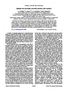
Title: Electrically controlled microvalves to integrate microchip polymerase chain reaction and capillary electrophoresis.
A microfluidic device for genetic amplification and analysis that makes use of fully integrated, electrothermally actuated microvalves. These electrically controlled microvalves are readily scaled to smaller dimensions and require minimal infrastructure for operation. In the background, the circular mottled regions at the bottom right and top left are expanding regions of solid polymer as a valve changes state.
ISSN 1473-0197
Suh Tutorial Review: Cell research with modified channels
Willis Monolithic valves and pumps for planetary exploration
Bashir Living cantilever arrays
Desai Controlled release of oral therapeutics
1473-0197(2008)8:7;1-X
See Govind V. Kaigala, Viet N. Hoang and Christopher J. Backhouse, Lab Chip, 2008, 8(7), 1071-1078.
Registered Charity Number 207890
Pages 993–1228
www.rsc.org
ISSN 1473-0197
Suh Tutorial Review: Cell research with modified channels
Willis Monolithic valves and pumps for planetary exploration
Bashir Living cantilever arrays
Desai Controlled release of oral therapeutics
1473-0197(2008)8:7;1-X
www.rsc.org/loc | Lab on a Chip
PAPER
Electrically controlled microvalves to integrate microchip polymerase chain reaction and capillary electrophoresis† Govind V. Kaigala,‡ Viet N. Hoang‡ and Christopher J. Backhouse* Received 19th February 2008, Accepted 6th May 2008 First published as an Advance Article on the web 5th June 2008 DOI: 10.1039/b802853b Microvalves are key in realizing portable miniaturized diagnostic platforms. We present a scalable microvalve that integrates well with standard lab on a chip (LOC) implementations, yet which requires essentially no external infrastructure for its operation. This electrically controlled, phase-change microvalve is used to integrate genetic amplification and analysis via capillary electrophoresis—the basis of many diagnostics. The microvalve is actuated using a polymer (polyethylene glycol, PEG) that exhibits a large volumetric change between its solid and liquid phases. Both the phase change of the PEG and the genetic amplification via polymerase chain reaction (PCR) are thermally controlled using thin film resistive elements that are patterned using standard microfabrication methods. By contrast with many other valve technologies, these microvalves and their control interface scale down in size readily. The novelty here lies in the use of fully integrated microvalves that require only electrical connections to realize a portable and inexpensive genetic analysis platform.
Introduction The health care system would greatly benefit if conventional molecular biology were made commonplace in clinics or for point-of-care applications. This has motivated the thrust towards the miniaturization and integration of molecular biology techniques, as well as the development of portable platforms. However, despite remarkable advances in ‘Lab on chip’ (LOC) technologies, thus far, few miniaturized microchipbased platforms are used in medical diagnostic applications. We believe this is largely due to the limitations imposed by the available microvalve technology.1 Currently, most microvalve implementations in the literature require substantial external infrastructure for operation,1,2 thus limiting the level of integration, functionality, portability and cost-effectiveness of the platform. In the present work we demonstrate a microvalve that is readily integrated into LOC systems and that is readily scalable, requires minimal external infrastructure, and based on standard LOC fabrication methods. We recently reported on a preliminary demonstration of an electrically actuated phase change microvalve.3 In the present work, we have improved this microvalve design by altering the valve architecture to withstand higher pressures, thus making it applicable to important applications such as the conventional polymerase chain reaction (PCR). We used this new valving technology to integrate PCR and capillary
Applied Miniaturization Laboratory, Department of Electrical and Computer Engineering, University of Edmonton, AB, Canada T6G 2V4. E-mail:
[email protected]; Fax: 1780 492-1811; Tel: +1780-492-2920 † The HTML version of this article has been enhanced with colour images. ‡ Authors contributed equally to this work.
This journal is © The Royal Society of Chemistry 2008
electrophoresis (CE) without the complex external infrastructure that is common in LOC implementations. As recently reviewed,4 microchip PCR has great applicability to medical diagnostics. Similarly, CE has diverse diagnostic applications.5,6 An effective strategy in diagnostics is the integration of genetic amplification and detection (e.g. PCR-CE) implemented on a single microchip. Such an integration has already proven to provide invaluable information from the genetic perspective for disease diagnostics, and would be particularly useful if made more amenable to portable use. In the past decade, there have been several reports and advancements in PCR-CE integration at the microfluidic chip level. Some notable demonstrations are by the groups of Mathies,7 Landers,8 Ramsey,9 Burns,10 Hong,11 Grodzinski,12 Fan,13 ourselves14,15 and others.7,8,10,16,17 Several of these demonstrations exhibit impressive functionality, but primarily represent significant levels of integration at the microchip level while requiring substantial external infrastructure for operation. Of central importance is the need for a microvalve to retain the reagents within the PCR volume during temperature cycling when the formation of bubbles tends to displace the reagents from the temperature-controlled region. Key to enabling portable and inexpensive platforms is the development of systems that primarily consist of the chip itself— with minimal external infrastructure. The Mathies group has made very significant strides in developing portable PCR-CE platforms—two notable recent demonstrations being Lagally et al.16 and Liu et al.18 Both ref. 18 and 16 make use of confocal optics with a photomultiplier tube (PMT) for detection and mini-pumps as the source for pressure/vacuum to actuate the membrane-based microvalves. Though highly impressive in terms of functionality and performance as well as portability, these systems have relatively complex instrumentation, thus increasing their cost, and hence are not ideally suited for inexpensive, portable, Lab Chip, 2008, 8, 1071–1078 | 1071
point-of-care applications. To realize portable and inexpensive platforms, we have chosen to simplify the system that operates the microchips. We recently demonstrated a microchipinstrumentation platform19 for PCR-CE integration that focused on reducing the cost of the optical components by using a highly simplified charge coupled device (CCD)-based system. The optics and pneumatic components together represent the bulk of the system cost. Both in our recent demonstration20 and that of Mathies,18 the pressure and vacuum requirements are satisfied by the miniaturized pumps integrated within the platform. Our demonstration in ref. 20 was an advancement in realizing a sufficiently inexpensive and yet portable PCR-CE system. However, after having reduced the cost of the optical components, much of the system cost is now associated with the microvalve infrastructure. The platform18,20 has a relatively large power budget on account of needing to power the minipumps, external valves, and solid-state relays for switching— the three necessary components for pneumatics. We here report on our improved thermoresponsive phase change microvalves. These readily-fabricated, electrically addressable microvalves are fully integrated within the microchip. The control and power requirements of the resulting system are low enough that the system can be run from a universal serial bus (USB) link to a computer—such low power implementations are expected to be greatly beneficial for point-of-care diagnostics. Electrical control for the actuation of microvalves requires minimal instrumentation and (as described below) is an approach that is readily scalable while being compatible with standard LOC implementations. As detailed in our recent microvalve work,3 there have been earlier demonstrations of thermally or electrothermally driven phase-change microdevices (e.g. using polyethylene glycol (PEG)3,21 and paraffin22,23 ), but devices reported to date have not been well-suited for PCR (i.e. conditions of elevated temperature and pressure). To our knowledge, the only two previous reports of an electrothermally actuated phase-change microvalve in the context of microchip PCR are that of Pal et al.24 and Liu et al.7 However, despite representing significant advances in the field, neither of these microvalves are ideally suited for PCR. Despite being electrically actuated, the valves of Pal et al.24 still relied upon external pressure and vacuum lines, while Liu et al.7 made use of paraffin microvalves that are usable only once, and have limited applicability as they require preloading of the sample in the chip. Although other phase-change valves have been reported, these do not provide a complete seal and are therefore incompatible with PCR: the nozzle diffuser work of ref. 21 and also the microvalves of ref. 22 and 23 where the fabrication process is quite complex. Our earlier work3 was the first to make use of electrothermally-actuated microvalves in PCR-like conditions within a commonly-used LOC architecture built with standard microfabrication procedures. The on-chip thermal expansion of PEG is used here to actuate the valve rather than by delivering externally-generated pressure/vacuum as is becoming a standard LOC approach (e.g. ref. 20, 25–27). PEG exhibits a large volumetric change during phase change from solid to liquid, and this is used to actuate the valves by controlling their temperature (Fig. 1). Using this improved PEG microvalve design, leak-free microvalve operation is achieved at higher pressure (up to 30 psi as opposed to 10 psi in ref. 3) to the extent 1072 | Lab Chip, 2008, 8, 1071–1078
Fig. 1 Cross-sectional (a and b) and top (c) views of the microvalve structure. Features in the control layer are 70 lm deep while those in the fluidic layer are 90 lm deep. The volumetric expansion of PEG as it undergoes a phase change is used to actuate a flexible PDMS membrane to open or close a path between two discontinuous channels. When the temperature is lower than ∼40 ◦ C PEG is in solid phase and the valve is open as in (a), and when temperature is maintained at ∼50 ◦ C PEG is in liquid phase and the valve is closed as in (b).
that we now demonstrate their use in a PCR-CE integration within a portable platform. In related work, we recently reported on an inexpensive ($1000) genetic analysis platform that made use of pneumatically actuated microvalves.20 Our demonstration here with phase change microvalves has resulted in the removal of about half the component cost of the system through the elimination of the pneumatic sub-system. Perhaps the most important advantage of these microvalves is that their simple electrical interface is readily scalable to smaller dimensions. As is apparent from the ongoing miniaturization of conventional microelectronics, with the present generations of on-chip electronics producing transistors at the nanoscale (i.e. sub-100 nm gate lengths), the technologies for electrical interface are well-developed. As we have demonstrated,28 glass-based microchips are well-suited for designs having several thermal elements, whether for control of the microvalves or PCR. The present electrically-operated microvalves are eminently suitable for implementing more complex microchips that require a larger number of miniaturized valves—without significant additional cost. By contrast, the costs of the pneumatic interface will scale with the number of valves, and the task of miniaturization of the pneumatic interface would be very challenging. To our knowledge, this is the first report of a microchip-based diagnostic platform based on an easily integrated, reusable microvalve technology whose fabrication is based on standard LOC technologies. Our microvalve design facilitates the integration of PCR and CE while greatly simplifying the external infrastructure This journal is © The Royal Society of Chemistry 2008
needed for the microvalve, thus enabling a lower power, portable and inexpensive diagnostic platform. Microvalve operation The microvalve consists of three layers—the control layer (glass), the flexible membrane (PDMS) and the fluidic layer (glass).25 There are two states of operation—open and closed. We make use of CarbowaxTM 1450, which has an average molecular weight of 1450 (melting temperature: 42–46 ◦ C) and exhibits a volume expansion of ∼25% upon melting. The actuation is achieved by the volumetric expansion of PEG during its phase transition from solid to liquid. We earlier presented a similar microvalve architecture3 and demonstrated leak-free sealing ability of the microvalve for pressures up to 10 psi. However, for wider applicability to a larger range of PCR protocols, a higher blocking pressure is necessary, and to achieve that in that design,3 the PEG needed to be heated far past its melting point so as to make use of the thermal expansion (∼0.065% ◦ C−1 ) in addition to the volumetric change. However, this led to the thermal degradation of the PEG3 and limited the operational lifetime of the valve. Furthermore, this additional heating required that we space the heater elements further apart both to avoid interference with the (temperature sensitive) PCR functionality of the microchip and to avoid heater–heater interference. To overcome the limitations in ref. 3 we implement a microvalve architecture based on the standard LOC architectures first proposed by Grover et al.,25 and subsequently used by ref. 8 and 16. Using the microvalve architecture as in Fig. 1, we are able to realize a leak-free condition to higher pressures by primarily making use of the phase change volumetric expansion, and making minimal use of the thermal expansion of the PEG, thus minimizing the thermal cross-talk on the microchip (details in Results and Discussion section). The volume of the PEG reservoir is designed to conformally deflect the PDMS membrane and also to cause additional pressure against the valve seat to ensure a leakage-free valve for up to 30 psi with the operating temperature in the PEG reservoir being 50 ◦ C—low enough (since this temperature is close to melting temperature) to ensure minimal degradation of PEG.29 This maximum fluid pressure (upstream) against which the microvalve can seal is determined by gradually increasing the pressure applied to colored fluid placed in the valved microchannel and measuring when leakage occurs through the closed microvalve. Details of the experimental set-up to evaluate the valve leak-free pressure measurement can be found in our earlier report.3
Methods and materials Microchip architecture, fabrication and assembly We make use of standard LOC microfabrication to fabricate this multi-layer chip. The etched glass layers (top and bottom) are sealed with a PDMS membrane (254 lm thick HT-6240, Bisco Silicones, Elk Grove, IL) to form the channels and reservoirs. Both the top and bottom glass substrates (1.1 mm thick, 4## × 4## , Schott, Germany) consisted of etched features (channels and reservoirs) while the PDMS membrane is unpatterned. The channels in the fluidic (upper layer in Fig. 1) layer were 90 lm This journal is © The Royal Society of Chemistry 2008
deep and 190 lm wide, while those in the control layer (lower layer in Fig. 1) were 70 lm deep and 150 lm wide. As in Fig. 2, the top glass layer requires through holes for fluid ports and for inlets for filling PEG and the PCR mixture. In the control layer, Pt/Ti is patterned to form resistive heating elements for both the PEG reservoirs and for the PCR reservoirs.
Fig. 2 Design of the glass–PDMS–glass integrated RT-PCR-CEmicrovalves chip used for genetic amplification and capillary electrophoresis. A reaction chamber for PCR is sealed off by a PEG microvalve on each side. Resistive elements (ring-like) are used for thermal control of the PCR chamber and of the PEG valves. Following PCR, the resulting products are pushed out into the CE section of the chip. High electric fields are then applied to move the products across the shorter CE channel (the injection channel), forming a sample plug at the intersection. The contents of this sample plug are then electrophoretically separated down the longer CE channel (the separation channel).
Details of the microfabrication procedure are in ref. 3. Thinfilm heaters of Pt/Ti are used for both thermal cycling for PCR and for microvalve operation—this layer is patterned using a lift-off technique much as described in ref. 3. Holes for the PEG inlet, PCR mixture inlet and outlet were drilled into the fluidic layer using a computer-controlled waterjet machine (Bengal, Flow International Corporation, Kent, Washington, USA). To ensure that no delamination of the chip occurred during the thermal cycling operation of PCR (e.g. 13 psi at ∼95 ◦ C), the glass and PDMS were irreversibly bonded by exposing the PDMS membrane for 6 min in a custom-built UV-ozone system.19 The chip is then loaded with PEG using either of the two procedures as described in the Methods and materials section. After PCR and CE operation, if required, the chips can be re-used after extensive chemical treatment according to the procedure described in ref. 20. PEG filling and sealing operation On this microchip all microvalves are connected to a common PEG loading inlet. The process of filling these microvalve reservoirs with PEG is performed only once during the assembly of the microchip and the device can be operated repeatedly without needing to refill the chip. In our previous work3 we had some evidence that the inlet channel and reservoir were too close to the valves (and hence too warm, especially given Lab Chip, 2008, 8, 1071–1078 | 1073
the elevated temperatures needed in that design), allowing some loss of actuation pressure. Thus the placement of the PEG inlet reservoir with respect to the microvalves is designed to ensure that the PEG in the inlet during the microvalve operation is in solid phase and thus blocks the movement of molten PEG in the microvalves. We make use of either of the two approaches developed here for filling the PEG reservoirs to form the valves. In the first approach (detailed in our earlier report3 ), the favorable wetting of PEG in its liquid phase and the displacement of the trapped air through the PDMS membrane allow filling of the dead end channels, taking several hours. The second filling approach (based on ref. 30) is more rapid and uses an external pressure difference to fill the channels. For this the chip is placed in a vacuum and the filling is completed in several minutes. Nevertheless, in this approach, the filling is independent of the wetting characteristic of the actuating polymer and hence the approach could be used even for polymers with unfavorable wetting properties. A central challenge with many phase-change polymers is that they are essentially incompressible (0.62 × 10⁻⁹ Pa−1 ,31 with the result that unless the chamber is filled with exactly the right volume of polymer, upon phase change it may not have enough room to expand and may destroy the chip or extrude polymer through the filling channel. As described below, we have developed a simple method of filling the valves with exactly the correct amount of polymer. Once the PEG is filled in the microchannel, microvalve and PEG reservoirs, the microchip is placed on a heat sink that is in contact with the microchip (Fig. 3) directly below the feed channels (all the channels connecting the PEG inlet reservoir to the microvalves as in Fig. 2) and the PEG inlet port. This results in PEG solidification in the inlet port and the feed channels (from the inlet reservoir to the microvalves) before the solidification occurs in the microvalve. The result of this is that the microvalve
goes from being fully filled with PEG (just above the phase change temperature of 42–46 ◦ C) to being approximately 80% filled (just below the phase-change temperature), thus realizing a normally-open microvalve. Given the small volume of the feed channels (∼80 nL is the volume of the feed channel which is directly connected to the microvalve, i.e. one leg of the L-shaped feed channel as shown in Fig. 2) as compared to the microvalve volume to be filled with polymer (∼500 nL), we assume that the contraction of the polymer in the feed channels does not significantly affect the amount of polymer in the microvalve). To close the valve, the resistive heater melts the polymer, thereby expanding it once again to fully fill the chamber. By heating the polymer to a slightly higher temperature it expands further, thereby compensating for any loss of polymer to the feed inlet and inducing a high internal pressure that forces the membrane down and seals the channel inlet and outlet (Fig. 1). Too high an actuation temperature may cause delamination and too low may not create an effective seal. We have found operating the resistive heater at 75 ◦ C gives reliable operation. By simulation we estimate that this corresponds to a microvalve temperature of 50 ◦ C (±2 ◦ C). Resistive element preparation and calibration We earlier demonstrated Pt/Ti-based resistive heating/sensing elements and optimized the heater/sensor geometry for uniform heating within a given region of a microchip.28 After fabrication, the Pt/Ti elements were annealed (at 1 atm) at ∼200 ◦ C for 2 h (in air) to ensure reproducible and stable behavior of the resistive element. These Pt/Ti elements were then calibrated in a temperature-controlled water bath (HAAKE Phoenix II C25P, Thermo Electron Corp. MA) to determine the relationship between temperature and resistance (the temperature coefficient of resistivity, TCR). As detailed in ref. 28 this allows us to measure the temperature of the Pt element both in the vicinity of the
Fig. 3 Cross sectional view of microchip along with the heat sink placement in relation to the microheaters of the PCR chamber and the PEG reservoirs. Spacing: PCR chamber (or PEG valve reservoir) radius: 1.5 mm. Inner resistive element radius: 2.3 mm. Outer resistive element radius: 2.5 mm. Radius of non-heat-sunk area: 3.5 mm. Distance between centers of PCR chamber and microvalve: 17 mm.
1074 | Lab Chip, 2008, 8, 1071–1078
This journal is © The Royal Society of Chemistry 2008
PEG reservoir and the PCR chamber. The inexpensive system we recently demonstrated,20 was used to operate this microchip (without any pneumatic components), using the thermal control of that system for the operation of the PCR heater. For each valve heater we added a mechanical relay (component cost ∼$1) that is directly actuated by an electrical signal from the microcontroller in the system. Approximately 80 mA and 5.5 V were applied to each valve heater (resistance of ∼70 X). The exact values of current and voltage used depended on the room-temperature resistance and the temperature coefficient of resistivity of the heater, and corresponded to a heater temperature of 75 ◦ C ± 1 ◦ C. (The dynamic temperature control used for the PCR heater is not needed for the valve heaters). Heat sink implementation To realize high densities in the placement of these microvalves and other thermally-sensitive components on a single microchip, it is important ensure that the microvalves and PCR elements are as thermally independent as possible. For this, regions of the microchip in which heating is not necessary are selectively heat-sunk to minimize thermal cross-talk.28 This allows these thermal modules to be spaced more closely together with minimum cross-talk. The intent is especially to minimize the interference between the heaters operating the microvalves and the PCR since inaccurate temperature control can produce
erroneous results.32 Additionally, since we desire a self-sealing microvalving structure, the inlet for loading the PEG needs to be placed sufficiently far away (for the specific dimensions of this microchip, a spacing of 10 mm away from the center of the PCR chamber the chip is at room temperature as in Fig. 4) from the valves to maintain its solid phase during the operation of the microchip. This self-sealing ensures that the PEG will not leak backwards during the regular microvalve operation, allowing pressure to be maintained at the remote valve seat (Fig. 3). The heat sink consists of a copper block with cooling fins for enhanced natural convection. Heated regions on the microchip are placed over trenches 1 mm deep in the surface of the copper block so that they are thermally isolated rather than heat-sunk. The design of the heat sink, its power requirements and the rapidity of its heat and cooling are the result of an optimization that is described in detail elsewhere.28 Inexpensive platform for performing thermal cycling and capillary electrophoresis The platform used here is much as in ref. 20, comprised of high voltage circuitry (for generating and switching up to 6 kV), an optical assembly consisting of a laser diode and a chargecoupled device (CCD) camera along with circuitry for thermal control. A custom software-based proportional integral derivative (PID) controller is implemented on the microcontroller
Fig. 4 FE simulation results of the designed microchip showing the temperature distribution along a line in the plane of the PCR chamber connecting the centers of the chamber and the valve. With the heat sink in place, the temperature distribution in the PCR chamber remains constant whether or not the heater for the microvalve is on (dashed line) or off (solid line). On the other hand, without the heat sink but given the same spacing between the chamber and valve, the operation of the valve significantly affects the temperature in the reaction chamber (∼5 ◦ C change). Hence, without the use of a heat sink, compact microfluidic chips cannot be realized for normal operation to independently control several thermally sensitive modules.
This journal is © The Royal Society of Chemistry 2008
Lab Chip, 2008, 8, 1071–1078 | 1075
of that system as described in more detail elsewhere.28 This is used to control the temperature of the heaters,28 and as a consequence, the temperature in the (intimately coupled) PCR chamber. The amplified PCR product is analysed with CE using laser-induced fluorescence (LIF) detection (Fig. 2). LIFbased detection was performed at 10 mm from the channel intersection. The separation of the DNA fragments (PCR primer and products) is achieved by pre-filling the chip with 4% Linear Polyacrylamide (LPA). Appropriate sizing of the product is achieved by running a DNA size standard. Further details on electrophoresis protocols and this platform can be found elsewhere.20 Microchip RT-PCR All RT-PCR mixtures included 25 ll of 2× reaction mixture (a buffer containing 0.4 mM of each dNTP, 2.4 mM MgSO4 ), 1 ll of the enzyme mixture comprising of SuperScript III RT and highfidelity Platinum Taq polymerase (Invitrogen Life Technology, Burlington, ON, Canada), 15–20 ll 5mM MgSO4 , 1 ll of each forward and reverse primer (10 lM) Primer set-I: Forward: 5# CCA GCA GAG AAT GGA AAG TC-3# and Reverse 5# -ACT TAA CTA TCT TGG GCT GTG AC-3# (the expected product size is 243 bp), 1 lg of RNA template, and double distilled water to reach a 50 ll volume. The primers were labeled with VIC dye and synthesized by ABI (Applied Biosystems, Foster City, CA). Thermal cycling conditions using the microchip were 45 ◦ C for 30 min, 94 ◦ C for 2 min, 35 cycles of 94 ◦ C for 15 s, 60 ◦ C for 30 s, 68 ◦ C for 30 s, and a final extension time of 7 min at 68 ◦ C. Both reagent and chip control experiments were performed (as detailed in ref. 20) but it should be emphasized that the present work is primarily a demonstration of the ability of our microvalves to be operable and leak-proof in a microchip integration of genetic amplification and analysis. We will further explore the CE performance of the integrated system elsewhere, but in its present form it is quite suitable for genetic diagnostics (further details can be found in ref. 20).
Results and discussion Spacing between thermal modules to minimize the effect of thermal cross-talk Thermal cross-talk is most pronounced during PCR operation when the microvalves are closed (heated) as is the PCR chamber. Finite element modeling (more details can be found in ref. 28) demonstrates that, for the given microchip design (with a heat sink implemented as in Fig. 3), when the chamber is at the maximum temperature required for most PCRs (∼95 ◦ C), regions of the microchip further than 10 mm from the center of the reaction chamber are at the temperature of the heat sink (Fig. 4, dashed line). The temperature of the PCR reservoir is not affected by variations in the temperature of the regions of the chip beyond this distance. This spacing depends on the microchip architecture (e.g. material thermal conductivities and thicknesses). Without the heat sink, but with the same heater spacing between the PCR chamber and microvalve, operating the microvalve substantially affects the temperature in the reaction chamber (changes by ∼5 ◦ C, Fig. 4). Hence, the two elements 1076 | Lab Chip, 2008, 8, 1071–1078
would have to be spaced much further away from each other to be thermally independent. The heat sink therefore allows thermal components to be placed more closely to each other while remaining independent, saving real-estate on the microchip. Microvalve performance The blocking pressure of the microvalve is measured by visually observing the ability of the valve to hold up against fluid (dyecolored water) placed in the fluid inlet to which a known pressure is applied using a syringe pump as in the experimental set-up in ref. 3. The external pressure is gradually increased in steps of 1 psi while holding each pressure state for 5 minutes and checking for leakage of colored water to establish the ability of the microvalves to hold against the external (i.e. upstream) pressure. For this, the microchip was mounted on a custom-built acrylic fixture selectively milled (1 mm deep) on the base such that the vicinity of the heater is not in direct contact with the acrylic, and hence not interfering with the valve response rate by redirecting heat flow away from the valves. In the current microchips, operating the heaters to maintain 50 ◦ C in the PEG reservoir resulted in a leakage-free microvalve up to a pressure of 30 psi. This blocking pressure of the microvalve was tested in excess of 10 times and demonstrated repeatable performance. Provided the sequence of the PEG solidification following the filling procedure during chip preparation was performed correctly, the confinement of fluid during operation of the microvalves has been consistent with the operating conditions as defined in the Methods and materials section. Three consecutive genetic sets of amplification and analysis (PCR-CE) were performed successfully, i.e. with successful amplification and detection, and with no evidence of valve leakage. Approximately 0.5 W is required to operate each microvalve. Two valves are required to confine the fluid within the reaction chamber, making their total power consumption ∼1 W. We believe this is a substantial reduction in power consumption while also reducing the complexity in instrumentation (vacuum/pressure pumps) and interfaces from the platform to the microchip as compared to demonstrations such as this in ref. 8 and 16. FE modeling and thermal analysis from first principles (not detailed here) indicate that the power required to operate these microvalves will scale approximately linearly with the dimensions of the microchip (i.e. half the size is half the power). Another favorable consequence of this reduction in the size of the microvalve is its effect on the thermal time constant, i.e. the time required for the system to reach steady state after thermal perturbation. Earlier,28 we established that the equilibration time of systems of this design scales quadratically with its dimensions (i.e. half the size is a reduction of four for the thermal time constant). A smaller thermal time constant is advantageous as it results in rapidity of the tests. The actuation time of the valves (both opening and closing) is primarily controlled by the heat transfer into and from the PEG reservoir much as described in our earlier microvalve demonstration.3 The opening and closing times are on the order of minutes—however this time remains small compared with the PCR processing time. As we previously reported, oxidation of the PEG may be leading to progressively slower opening times3 by lowering the melting temperature of the PEG resulting in a longer time required for This journal is © The Royal Society of Chemistry 2008
PEG solidification (this is a well-known problem with PEG). It becomes increasingly difficult to solidify the PEG via passive cooling as its melting point approaches room temperature. For the operating conditions of the microvalve used here and after a typical 1.5 h PCR we find that valve opening time increases to be several minutes. However, by changing to a more robust polymer (e.g. paraffin as in ref. 22 and 23), by further scaling the chip dimensions, or by using a heat sink, we expect to attain opening and closing times of several seconds. Genetic amplification and detection with PEG valves As a preliminary demonstration of the integration of these electrically controlled valves, we demonstrated the use of the microchip platform to amplify and detect transcripts encoding b2 microglobulin (b2M) from total RNA. For this, RNA was isolated from KMS-34, a multiple myeloma (MM, cancer) cell line. The primers were designed to amplify a 243 bp fragment from RNA or from genomic DNA. The PEG-filled microvalves were able to seal the reaction chamber even at elevated temperatures (95 ◦ C) without leakage, and all throughout the thermal cycling (as per the protocol detailed in methods). During thermal cycling, the PCR mixture is completely confined within the chamber with no observable loss in volume. The positive PCR product peak (Fig. 5) indicates the successful amplification of the target gene. The limit of detection (LOD) of the system is dictated to a large extent by the optics of the platform, which are not the focus of this paper, but were explored in our earlier demonstration20 where the LOD was found to be 0.1 ng lL−1 of end-labeled PCR. The focus of this paper is upon the demonstration that the valves operate reproducibly and are entirely suitable for this application.
amplification and separation/detection techniques through the use of a PEG-based phase-change microvalve. The microvalves are triggered thermally using resistive heaters and such heaters are also used to thermally cycle the PCR mixture within the reaction chamber for genetic amplification. The microvalves effectively confine the reaction mixture during thermal cycling for a wide variety of PCR protocols. We have earlier demonstrated the applicability of similar PCR-CE microchips to viral load assessment,17 transcript level estimation in gene expression for disease diagnosis and monitoring,14 and single nucleotide polymorphisms (SNPs) for applicability in the evaluation of adverse drug reactions15 and the microchip demonstrated here can be readily applied to such applications. Clearly, demonstration of such clinical applicability is important in the development of point-of-care applications. These electrically responsive valves, on account of their low power consumption and minimal external drive electronics, are highly suited for microelectronic implementations. They also eliminate external infrastructure such as external pumps, external pneumatic valves, solid-state relays and other coupling instrumentation (interfaces) of pressure/vacuum on the chip. The power consumption of the heaters (for PCR and valves) could be reduced further by reducing their size. Simulations have shown that halving all dimensions would halve the power consumption while reducing the thermal response time by a factor of four. Such miniaturization would allow a large number of components to be placed in a given microchip area, allowing for parallel tests—a must for clinical usage. We believe that the feasibility of shrinking such microvalves (while still having each microvalve independently addressable) will greatly assist in improving levels of integration in future LOC implementations of highly miniaturized and portable diagnostics systems.
Acknowledgements This work was funded by grants from the Natural Sciences and Engineering Research Council (NSERC). GK is funded from NSERC, iCore, and the Graduate Student Supplement Program from the National Institute of Nanotechnology. VH is supported by the NSERC, Alberta Ingenuity Fund (AIF) studentships, iCore. The authors would like to thank Jana Lauzon for technical assistance and Dr Song for discussions on microchip design.
References Fig. 5 Fluorescence (arb. units) versus time (seconds) from the chip shown in Fig. 2 and 3. The b2 microglobulin (b2M) gene was successfully amplified and subsequently separated/detected using the tri-layer chip within the inexpensive genetic analysis platform. A rise in the baseline is observed after the PCR primer peak (first peak) and we attribute this to electro-osmotic flow (EOF)-induced leakage at the intersection.
Conclusions and future directions In the present work we demonstrate a means of overcoming one of the technological (and cost) barriers to LOC implementation of inexpensive point-of-care genetic analysis systems. For this, we demonstrate a microchip that effectively integrates genetic This journal is © The Royal Society of Chemistry 2008
1 K. W. Oh and C. H. Ahn, J. Micromech. Microeng., 2006, 16, 13–39. 2 M. J. Felton, Anal. Chem., 2003, 75, 429A–432A. 3 W. H. Song, J. Kwan, G. V. Kaigala, V. N. Hoang and C. J. Backhouse, J. Micromech. Microeng., 2008, 18, 1–9. 4 M. G. Roper, C. J. Easley and J. P. Landers, Anal. Chem., 2005, 77, 3887–3894. 5 E. Sz´antai and A. Guttman, Electrophoresis, 2006, 27, 4896–4903. 6 K. Kleparnik and P. Bocek, Chem. Rev., 2007, 107, 5279–5317. 7 R. H. Liu, J. Yang, R. Lenigk, J. Bonanno and P. Grodzinski, Anal. Chem., 2004, 76, 1824–1831. 8 C. J. Easley, J. M. Karlinsey, J. M. Bienvenue, L. A. Legendre, M. G. Roper, S. H. Feldman, M. A. Hughes, E. L. Hewlett, T. J. Merkel, J. P. Ferrance and J. P. Landers, Proc. Natl. Acad. Sci. U. S. A., 2006, 103, 19272–19277. 9 J. Khandurina, T. E. McKnight, S. C. Jacobson, L. C. Waters, R. S. Foote and J. M. Ramsey, Anal. Chem., 2000, 72, 2995–3000.
Lab Chip, 2008, 8, 1071–1078 | 1077
10 R. Pal, M. Yang, R. Lin, B. N. Johnson, N. Srivastava, S. Z. Razzacki, K. J. Chomistek, D. C. Heldsinger, R. M. Haque, V. M. Ugaz, P. K. Thwar, Z. Chen, K. Alfrano, M. B. Yim, M. Krishnana, A. O. Fuller, R. G. Larson, D. T. Burke and M. A. Burns, Lab Chip, 2005, 5, 1024–1032. 11 J. W. Hong, T. Fujii, M. Seki, T. Yamamoto and I. Endo, Electrophoresis, 2001, 22, 328–333. 12 Y. J. Liu, C. B. Rauch, R. L. Stevens, R. Lenigk, J. N. Yang, D. B. Rhine and P. Grodzinski, Anal. Chem., 2002, 74, 3063–3070. 13 C. G. Koh, W. Tan, M. Q. Zhao, A. J. Ricco and Z. H. Fan, Anal. Chem., 2003, 75, 4591–4598. 14 J. VanDijken, G. V. Kaigala, J. Lauzon, A. Atrazhev, S. Adamia, B. J. Taylor, T. Reiman, A. R. Belch, C. J. Backhouse and L. M. Pilarski, J. Mol. Diagn., 2007, 9, 358–367. 15 J. Chowdhury, G. Kaigala, S. Pushpakom, J. Lauzon, A. Makin, A. Atrazhev, A. Stickel, W. G. Newman, C. J. Backhouse and L. M. Pilarski, J. Mol. Diagn., 2007, 9, 521–529. 16 E. T. Lagally, J. R. Scherer, R. G. Blazej, N. M. Toriello, B. A. Diep, M. Ramchandani, G. F. Sensabaugh, L. W. Riley and R. A. Mathies, Anal. Chem., 2004, 76, 3162–3170. 17 G. V. Kaigala, R. J. Huskins, J. Preiksaitis, X. L. Pang, L. M. Pilarski and C. J. Backhouse, Electrophoresis, 2006, 27, 3753–3763. 18 P. Liu, T. S. Seo, N. Beyor, K. J. Shin, J. R. Scherer and R. A. Mathies, Anal. Chem., 2007, 79, 1881–1889. 19 G. V. Kaigala, S. Ho, R. Penterman and C. J. Backhouse, Lab Chip, 2007, 7, 384–387.
1078 | Lab Chip, 2008, 8, 1071–1078
20 G. Kaigala, V. N. Hoang, A. Stickel, J. Lauzon, D. Manage, L. M. Pilarski and C. J. Backhouse, Analyst, 2008, 133, 331– 338. 21 P. Sethu and C. H. Mastrangelo, Sens. Actuators, A, 2003, A104, 283–289. 22 E. T. Carlen and C. H. Mastrangelo, J. Microelectromech. Syst., 2002, 11, 165–174. 23 E. T. Carlen and C. H. Mastrangelo, J. Microelectromech. Syst., 2002, 11, 408–420. 24 R. Pal, M. Yang, B. N. Johnson, D. T. Burke and M. A. Burns, Anal. Chem., 2004, 76, 3740–3748. 25 W. H. Grover, A. M. Skelley, C. N. Liu, E. T. Lagally and R. A. Mathies, Sens. Actuators, B, 2003, 89, 315–323. 26 J. S. Marcus, W. F. Anderson and S. R. Quake, Anal. Chem., 2006, 78, 956–958. 27 C. J. Easley, J. M. Karlinsey and J. P. Landers, Lab Chip, 2006, 8, 601–610. 28 V. N. Hoang, MSc thesis, Electrical and Computer Engineering, University of Alberta, Edmonton, Canada, 2008. 29 J. Glastrup, Polymer Degradation and Stability, 1996, 52, 217– 222. 30 C. L. Hansen, E. Skordalakes, J. M. Berger and S. R. Quake, Proc. Natl. Acad. Sci. U. S. A., 2002, 99, 16531–16536. 31 G. T. Dee, T. Ougizawa and D. J. Walsh, Polym. Degrad. Stab., 1992, 33, 3462–3469. 32 C. T. Wittwer and D. J. Garling, Biotechniques, 1991, 10, 76–83.
This journal is © The Royal Society of Chemistry 2008