cey - sin2 e>. CII,l. = EOExy. GLJ = oyy - oxy. G(I,l = oxy ..... [IO] J. L. Allen, A. T. Adams, W. J. Gajda, and W. F. Walker, âElec- tromagnetic properties and effects of ...
__
IEEE TRANSACTIONS ON ELECTROMAGNETIC COMPATIBILITY, VOL. 35, NO. 3, AUGUST 1993
357
Transient Propagation in Anisotropic Laminated Composites Ming-Shing Lin, Chien-Min Lin, Member, IEEE, Ruey-Beei Wu, Member, IEEE, and Chun Hsiung Chen, Senior Member, IEEE
Absmcr-This paper presents a detailed analysis of transient response of electromagnetic pulse (EMP) and Gaussian pulse in anisotropic laminated composites. To this end, both the equivalent-transmission-line-circuit(ETLC) model and the finite-difference time-domain (FDTD) method are adopted in the time-domain analysis. In this study, numerical results are presented for graphite/epoxy (GIE) laminates, based on a model which treats each lamina as a homogeneous and anisotropicsheet. The factors to influence the transient response of anisotropic laminated composites, such as laminate thickness, fiber orientation, and the angle, frequency contents, and polarization of incident wave, are also investigated.
I. INTRODUCTION
T
HE INCREASING use of composite materials in industrial and military applications necessitates intensive studies of their electromagnetic properties. An investigation of the electromagnetic properties of advanced composite materials was introduced by Allen, Walker, and Siarkiewicz [ l], including their electrical constitutive parameters and electromagnetic shielding properties. The electrical and electromagnetic impacts on composites, such as lightning protection, shielding effectiveness, electrical system, antenna operation, static electricity, and radar cross section, were also discussed by Blake [2] in 1976. From these studies, it is noted that composite materials can only provide a marginal conductivity and they are highly anisotropic in their electrical constitutive parameters, which makes the study of their electromagnetic properties an important issue in electromagnetic compatibility (EMC). Laminated composite panels whose fibers do not possess a preferred orientation were modeled as a uniaxially anisotropic conductivity or dielectric slab. These were studied by Casey [3], both in frequency and time domains. However, design information for the composites, whose fibers possess a preferred orientation, is not available. The nonspecular electromagnetic scattering from finite composite laminates was investigated by Krohn and MedgyesiMitschang [4] in frequency domain, using the electric-field integral equation together with the entire domain Galerkin expansion. Although they could get an accurate solution for Manuscript received April 27, 1992; revised March 18, 1993. This work was supported by the National Science Council of the Republic of China under Grant NSC 82-0404-E-002-237. The authors are with the Department of Electrical Engineering, National Taiwan University, Taipei, Taiwan 10617, Republic of China. IEEE Log Number 9209375.
nonspecular scattering, the mathematical formulation was not easy to extend to multiplied laminates. By constructing the solution of frequency-domainMaxwell’s equations in each composite lamina, imposing the boundary conditions on the interfaces, and finally cascading the wave-transmission matrix for each lamina, one may derive the relation among the incident, reflected, and transmitted fields. This was called the wave-transmission-matrix (WTh4) method [ 5 ] and may be used to solve the laminated and anisotropic composites which are illuminated by an obliquely incident plane wave. Basically, one may obtain the desired time-domain response from the frequencydomain one by the fast Fourier transform (FFT) algorithm. However, for the transient pulses considered in this study, this FFT approach is not efficient and requires a lot of sampled points because the transient waveforms rise sharply during a very short early time and then last for a long period. Recently, an equivalent-transmission-line-circuit (ETLC) model [6] was developed mainly to treat the transient problem of a plane wave in inhomogeneous, anisotropic, and transversely lossy slabs. This model was established based on the analogy between the field equations and the coupled transmission line equations [7], [8] which were approximated by suitable lumped circuits and then solved by the circuit simulation program such as ASTAP [7], PSPICE [9], etc. In this study, the ETLC model is adopted to investigate, in detail, the electromagnetic propagation problem of laminated and anisotropic composites both in time and frequency domains. To check the accuracy of the time-domain results, the finite-difference time-domain (FDTD) method is also applied to treat the transient problem of normal incident cases. In this study, the numerical results for graphite / epoxylaminated panels are included and discussed in detail. The results obtained by the ETLC model are compared with those by the WTM method in frequency domain and those by the FDTD method in time domain. The factors influencing the electromagnetic propagation properties of laminated composites, such as number of plies, fiber orientation, and the angle, frequency contents, and polarization of incident wave, are discussed. Also included in this study is an empirical formula to estimate the copolarization terms of transmittivity, based on the low-pass characteristics of graphite/epoxy composites. Finally, an unusual transmittivity rise phenomenon explained by multireflection resonance is investigated.
0018-9375/93$03.00 0 1993 IEEE
Authorized licensed use limited to: National Taiwan University. Downloaded on February 25, 2009 at 00:45 from IEEE Xplore. Restrictions apply.
IEEE TRANSACTIONS ON ELECTROMAGNETIC COMPATIBILITY, VOL. 35, NO. 3, AUGUST 1993
358
The plane wave of an arbitrary transient waveform and incident angle 0, under consideration, is expressed as
I
reflected wave
S_,~ ( z ;
R ( z , z , t )=
[,
00
€0 ‘1
w)ejWte--jkoxsine
d~
00
~ ( Z ; w ) e j w t e - - j k o x s i n ewd
(2)
where IC0 = w= w / c is the free-space wavenumber and c is the velocity of light. In this study, it is desired to find the fields € ( z ,t) and % ( z ,t) at z = 0 plane, under an obliquely incident plane wave of arbitrary waveform P ( t )and @(t).
L
E’ incident -’
~ ( zz , t ) =
dl-
Fig. 1. Geometry of M-ply laminated composites.
Matrix
111. EQUIVALENT-TRANSMISSION-LINE-CIRCUIT (ETLC) MODEL The ETLC model [6] is adopted to treat the transient problem for the anisotropic laminated composites. This model is discussed by the coupled transmission line equations
0
together with the boundary conditions between the voltage and current Y
Fig. 2. Global coordinates and principal coordinates for laminated composites.
11. STATEMENT OF PROBLEM Consider the propagation problem associated with the anisotropic M-ply laminated composites which are illuminated by an obliquely incident plane wave as shown in Fig. 1. From the investigation of electrical constitutive parameters of laminated composites in [lo]-[12], one may regard each individual lamina as a homogeneous and anisotropic sheet. The electrical parameters of the mth ply are described by the permeability PO, anisotropic permittivity EO:,, and conductivity Z m , respectively. The tensors Zm and 5, can be expressed as Ex,
Exy
0
0
0 0
t ) + qpip(O,t) = 2 $ ( t ) ,
at incident boundary at transmitted boundary. (4) To facilitate the analysis, the plane wave is decomposed into the Ell -wave and El-wave components, respectively. The Ell (or E l ) wave means the one with E-field parallel (or perpendicular) to the z--z plane of incidence. The voltage and current wave vectors are defined as zlp(O,
‘;“
{ zlp(D,t) + q p i p ( Dt),
= 0,
(5)
The equivalent inductance, capacitance, and conductance matrices in (3) are given by sin2 B L=u0[1-6_
E,,
-eyx
where txx
fxy EYY E22
+
= ex! cos2 4 cy! sin2 4 = cyX = (E.! - c y / ) cos4sin4 = ex! sin2 4 = EZ’.
+ cy/ cos2 4
Here (ex,, cy’, E , , ) are the permittivities with respect to the composite’s principal axes, and 4 is the angle between the global and the principal axis of each lamina as shown in Fig. 2. Similar expressions are used for the conductivities ( g x x , c r y = u y x , g y y , e,,).
-r
I
:]
eyy - sin2 B
1
In (4),the subscript ‘‘p” = “11’’ (or “1”) denotes that the incident field is the Ell (or E l ) wave; while 711= qocosI9 and q l = qo/ cos 6 are the characteristic impedances of the Ell and E l waves, respectively; and qo = && is the intrinsic impedance of the free space. From the coupled transmission line equations (3) together with the boundary conditions (4), an equivalent-transmissionline-circuit (ETLC) model can be established as shown in Fig.
LIN
e1 ol.: TRANSIENT PROPAGATION
359
IN ANISOTROPIC LAMINATED COMPOSITES
. T -section
I
I
/////////////////I Fig. 3. Equivalent-transmission-line-circuit model.
3. Thus solving the electromagnetic propagation problem of the composites is then equivalent to finding the frequencyand time-domain solutions from the ETLC model. In order to implement the ETLC model on the circuit simulation program, the transmission lines in Fig. 3 should be discretized and approximated by cascading lumped T and R circuits, such as T-T-R and T-T-T circuit models. The R-T-R (or T-T-T) circuit model is the one which provides shunt elements (or series elements) at the source and load ends. It was noted that the R-T-R circuit model has better convergence and numerical stability properties than the T-R-T one [6]. For the propagation problem of Fig. 1, the detailed lumped T and R circuits for a section of length 1 are shown in Fig. 4. The circuit elements are related to the electrical parameters of the composites by CII,II =
- cXy)
c L , ~= ~
(
- cey 6
e>
- ~sin2 ~
. T - section I L l l I1
0
”
‘
Fig. 4. Detail of
T and
?r
\
sections.
obtained for any incident field waveform (t). The definitions of “p” and “q” are the same as those defined in the frequencydomain analysis.
CII,l. = EOExy GI(,((= o e x - ox, GLJ = oyy - o x y sin2 e
G(I,l= o x y (7)
and the coefficient k of mutual coupling between two lines is equal to zero. These lumped-circuit models are directly suitable for use in standard circuit analysis programs such as PSPICE [9]. Accordingly, the analysis of transient propagation in anisotropic laminated composites may easily be conducted by the PSPICE computer simulation. The output waveform of the time- and frequency-domain field solutions can be plotted directly based on the interactive graphics facility of PSPICE. In PSPICE computer code, the frequency-domain analysis can be conducted by the command “.AC“. From the output data of PSPICE program, we can get the transmittivity coefficients ~ I , , I , ~ I JT,L J , and Tl,1l and the reflectivity coefficients R I I JR, I I ,R~I,J , and R ~ , I in I , the frequency domain, by the following definitions:
IV. FINITE-DIFFERENCE TIME-DOMAIN(FDTD) METHOD The FDTD method is also used to obtain the transient solution of the problem in Fig. 1 with normally incident cases. For this one-dimensional propagation problem, Maxwell’s curl equations for four unknowns &x, Ey, Ify, and Ifz may be discretized using Yee’s algorithm [13] as
l A + ----4[&,n(k + 1) - €,n(k)] PO A
-
&,“+‘(k)
=
1 At ---[€,n(k Po A
1 1- C5D5
”P
Here the first subscript “p” = “I\” (or “1”) denotes that the incident field is the Ell (or E l ) wave, and the second subscript “q” = ‘ I(’ (or “l”)denotes that the reflected and transmitted fields are the Ell (or E l ) wave. The time-domain analysis may also be conducted by the command “ . T U N . Then, the transient waveforms for reflected and transmitted fields t?;,q(t) and &i,q(t) may be
Authorized licensed use limited to: National Taiwan University. Downloaded on February 25, 2009 at 00:45 from IEEE Xplore. Restrictions apply.
+ 1) - €,“(k)]
IEEE TRANSACTIONS ON ELECTROMAGNETIC COMPATIBILITY, VOL. 35, NO. 3, AUGUST 1993
360
Time ( 1 )
Here the coefficients are defined by -40
I
i
(de) -6 0
-e 0 c 3=
sc
[
(YExy-
E'(f)
2aat]
-100 -1 2 0 -1 4 0
-
7.0.lns7. 1 ns 7=10ns-
2GHz 4GHz 6GHz 0GHz O.2GHz 0.4GHz O.6GHz O.8GHz 20MHz 4OMHz GOMHz BOMHz
lOGHz
1.OGHz
lOOMHz
Freq ( 1 )
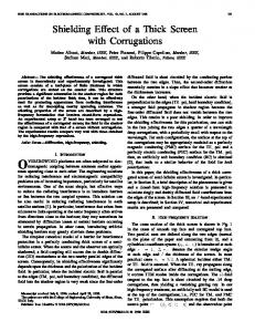
(b) Fig. 5. Gaussian pulses with ( 7 , t o ) =(0.1 ns, 1 ns), (1 ns, 10 ns), and (10 ns, 100 ns). (a) lime-domain waveform. (b) Frequency spectrum.
where
(Y
=
V. INCIDENT TRANSIENT PULSES - tXytyx),Sc = 2to ( ~ ( o , , t ~ ~ Two types of incident wave are considered, Le., the Gauss= 2t0 + a(@yy~xx - gxytyx)At.In (91, ian pulse and the electromagnetic (EM) pulse, such as nuclear
l/(txxEyy
+
o y x ~ x y ) A and t, s d A is the space lattice increment in the z direction, At is the unit time increment, and f n ( k ) denotes f ( n A t , kA). By the
system of finite-differenceequations (9),the new value of field component at any lattice point depends only on its previous value and also on the previous values of the components of the other fields at adjacent points. To ensure the stability of the numerical iterative scheme, At is limited by the criterion At 5 A/vm,, [14], where Wm,, is the maximum phase velocity within the media. Here, we choose 2cAt = A in the numerical computation. For practical computation, the finite-difference grids should be finite. In our propagation problem, the medium is of infinite extent in the z direction; therefore, a suitable absorbing boundary condition (ABC) should be implemented in the analysis. Here, the Mur's first-order approximate ABC [15] is adopted and expressed as
where the subscript 0 denotes the grid point at the truncation wall and the subscript 1 denotes the grid point at one space lattice increment inside the truncated wall.
electromagnetic pulse (NEMP) and lightning waveform. The Gaussian pulse is given by p ( t ) = e-[(t-to)/712
4t)
(12)
where t o is the peak delay time, T is the pulsewidth, and =
{ (i:
t>O
t < 0.
The value of pulsewidth T determines the frequency content of the Gaussian pulse. Three cases of (7, t o ) are discussed: (0.1 ns, 1 ns), (1 ns, 10 ns), and (10 ns, 100 ns). The time-domain waveform and the frequency spectrum of each Gaussian pulse are shown in Fig. 5(a) and (b). Note that the frequency content of the pulse with small T(T = 0.1 ns) is about 100 times higher than that with large T (T = 10 ns), but the frequency content is independent of the peak delay time to. Here, we refer to the pulses with (0.1 ns, 1 ns), (1 ns, 10 ns), and (10 ns, 100 ns) as high-frequency (HF), medium-frequency (MF), and low-frequency (LF) Gaussian pulses, respectively. The EM pulse waveform discussed is double exponential as given by
Authorized licensed use limited to: National Taiwan University. Downloaded on February 25, 2009 at 00:45 from IEEE Xplore. Restrictions apply.
361
LIN et al.: TRANSIENT PROPAGATION IN ANISOTROPIC LAMINATED COMPOSITES
:I
--
Ons Ons
lOOns Ins
20017s 300ns 400ns 5 W n s 2ns 3ns 4ns 5ns
-80 -
-
--ZWKHz 20Mlz
---
\
lOMHz 1 GHz
1.OMI-k lOOMHz
lOOMHz 1 OGHz
and uyt = azl = 50 mho/m are obtained for subsequent analysis. In the following calculations, the thickness d of each lamina is 5 mils. To apply the ETLC model, we let urz= 0 in the problem of Fig. 1 and (1). This assumption does not affect the accuracy of the results in normally incident cases, and it only slightly affects the accuracy in obliquely incident cases if the incident angle 0 is less than 30". Here, the number N of 7r and T sections per lamina is depended on the effective skin depth of the composites, and the n-T-7r circuit model is used in the computations. Although the ETLC model is mainly used here for transient analysis, it is also applied to the frequency-domain problem. To provide the frequency-domain characteristics, we analyze the four-layer G/E laminated composites with fiber orientation [0°/450/900/ - 45'1 both by ETLC model and the wave-transmission-matrix (WTM) method [5]. The results are shown in Fig. 7(a) and (b) for Ell- and El-waves incidence, respectively. Excellent agreement among the results confirms the accuracy of the ETLC model. Fig. 7(a) and (b) illustrates that the frequency response of G/E composites reveals a lowpass characteristic. This characteristic can be explained by the detailed lumped circuits of the ETLC model, shown in Fig. 4. In the lower frequency range, the conductance circuit elements are the dominant ones. By these arguments, an empirical formula for estimating the copolarization terms Tp,pin the lower frequency range may then be proposed as
Freq ( f ) 0
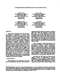
(b) Fig. 6. Electromagnetic pulses with (a,p) = (1 x lo', 1 x lo8) and (2 x 109,3 x lo9). (a) Time-domain waveform. (b) Frequency spectrum.
where EO= l/(e--ato - e-Pto), and to = ln(p/a)/(p - a). The values of a and p determine the shape and frequency spectrum of the EM pulse. We shall consider two EM pulses defined by Lee and Dudley [16]. The time-domain waveforms and the frequency spectra of these two pulses are shown in Fig. 6(a) and (b). In the case of a = 1 x lo7 and p = 1 x lo8, the amplitude of frequency spectrum drops approximately 50 dB as the frequency goes from dc to 100 MHz. And for the case of cy = 2 x lo9 and p = 3 x lo9, the frequency spectrum drops 50 dB over the frequency range from dc to 7 GHz. Because the frequency content of the latter is much higher than that of the previous, we refer to the latter as the high-frequency EM pulse and to the previous as the low-frequency EM pulse.
m=l
Here ( a , ~(mho/m) ) ~ is the effective conductivity of the mth ply composite lamina which depends on material properties, fiber orientation, and incident wave polarization, and is given by (Ueff>m =
{
(oz! Im
COS'
4 + (v,!)m sin2 9, for wave + (a,!), cos2 4, for E L wave
sin2 4
(azt)m
and qp is the characteristic impedance of incident wave as defined in (4).For the cases in which each lamina has equal thickness (dm = d ) , (15) can be reduced to 3
0
where VI. RESULTS Anisotropic laminated composite materials such as the graphite/epoxy (GE) composites are the main concern of this study, because they are widely used in aircraft structures [l]. For these composites, their conductivities are mainly provided by the fibers because those of epoxy matrices may be neglected. Over the frequency range of this study, the plies are electrically very thin and the fiber separation is a tiny fraction of a wavelength. Thus the tensor constitutive parameters of G/E specimens may be estimated by the method suggested by Casey [3], by which the conductivities az)= 4 x lo4 m h o h
. r~
1
In Fig. 7(a) and (b), we also notice that there is an unusual rise on the transmittivity curves near 1 GHz, especially for the E l wave incidence. This phenomenon may be explained by the concept of quarter-wavelength transformer or multireflection resonance. When a wave is multiply reflected in a region, the cross-polarization terms TI,^, T_L,II, R I I , and ~ , Rl,1l will be dominant if the thickness of the region is near a quarterwavelength.
362
IEEE TRANSACTIONS ON ELECTROMAGNETIC COMPATIBILITY, VOL. 35, NO. 3, AUGUST 1993
convergent results, the length I of the 7r or T section in the ETLC model should be less than Seff/2, while the space lattice size A in the FDTD method should be less than Se,/l0. The effective skin depth Seffof laminated composites is defined by
*x10
\.
Tx
For a pulse with a maximum frequency component fmax = 10 GHz and the effective conductivity geff= 2 x lo4 mhoslm, the effective skin depth is Se, = 3.56 x m. In this case, 1 (or A) should be less than 1.78 x (or 3.56 x m. Therefore, for a lamina with a thickness d = 5 mils, the number N of 7r or T sections (or lattice points) should be greater than 7 (or 35) in the computation of the ETLC model (or the FDTD method). Special consideration in stability and absorbing boundary conditions should be given in the FDTD method, and the computation time of the ETLC model is much less than that of the FDTD method. Therefore, the FDTD method is mainly used in the accuracy check. The shape of the transmitted fields Et can be predicted by the low-pass characteristic of the composites. The major frequency content of low-frequency EM pulse is from dc to 100 MHz. From Fig. 7, it is found that this frequency content is within the passband of the composites. In other words, the frequency response (transmittivity) of composites is a constant value in that frequency range. Therefore, for a low-frequency EM pulse, the composites do not essentially affect the shape of transmitted fields (Fig. 8(a)). Of course, the peak values can be estimated by (16). Conversely, the of and major frequency content of high-frequency EM pulse covers the nonpassband of composites. Consequently, the shape of transmitted fields in Fig. 8(b) is distorted and there is a greater reduction in the peak values as compared with the low-frequency pulse. The effect of varying the incident angle 8 on the transient properties of four-layer G/E laminated composites with fiber orientation [Oo/45'/9O0/ - 45'1 is investigated. Shown in Fig. 9 are the results with low-frequency Ell EM pulse incidence. Clearly, the peak value increases as 8 increases for all fields, and this is a consequence of the fact that the E field is inclined with respect to the direction of fiber orientation. The peak value of Elf,!, can also be estimated by (16). The transient propagation properties of a unidirectional M layer G/E with low-frequency EM pulse incidence are shown in Fig. 10. As expected, the incident Ell-wave component suffers much more attenuation than the incident El-wave component when they are passing through the anisotropic G/E layer, because 0,)is much larger than oyt. One should notice the phenomena associated with the increasing thickness (D= M d ) :the decrease of the peak value, the increasing time delay of the main peak, and the increasing pulsewidth of the transmitted field Ei,ll. The peak values of the transmitted field also decrease as thickness and the total field E; increases. However, the peak value of the total field E i Ei,ll in the "0" region is only slightly affected by the thickness. The resulting time-domain responses of four-layer G/E composites with fiber orientation [Oo/45'/9O0/ - 45'1 and with normally incident Gaussian pulses are shown in Fig. 11.
€i,,l
F req (Hz) (b)
Fig. 7. Transmittivities and reflectivities of four-layer G/E laminate composites with fiber orientation [Oo/45'/9O0/ - 45'1. Theoretical results by WTM [5] are included for comparison. (a) Ell wave and (b) E l wave are normally incident on the composites with lamina thickness d = 5 mils and electrical constitutive parameters: uxt = 4 x lo4 mho/m, uvt = u,t = 50 mho/m, e x ! = cy! = e,! = 5. The same constitutive parameters are used in Figs. 8-11.
To check the accuracy of the time-domain results, both the ETLC model and the FDTD method are employed in the transient analysis. For this purpose, we examine the transient propagation properties of four-layer G/E laminated composites with fiber orientation [Oo/45'/9O0/ - 45'1. Here, the EM pulses are normally incident on the composites. The resulting time-domain responses to the low-frequency and high-frequency EM pulses are shown in Fig. 8(a) and (b), respectively. Excellent agreement among the results again confirms the accuracy of both methods. To obtain accurate and
+ €I,l
+
LIN et al.: TRANSIENT PROPAGATION IN ANISOTROPIC LAMINATED COMPOSITES
363
6
~ ' ~ 1 0 ~ 2
0
~
~
1
0
~
I
Ons
lOOns
2Wns
300ns
4OOns
51
I
Ons
IS
lOOns
Time
200ns
300ns
400ns
5(
1s
Time Fig. 9. Effect of varying incident angle 8 on transient properties of four-layer
G/Elaminated composites with fiber orientation pattem [Oo/450/900/-450]. Incident wave is low-frequency Ell EM pulse.
2 5 2 0
Ex104
1 5
1 0 0 5
0
I
Ons
Ins
2ns
3ns
4ns
!
Time (b) Fig. 8. Time-domain response of four-layer G E laminate composites with fiber orientation [0°/450/900/ - 45O]. Theoretical results by FDTD method are included for comparison. (a) Low-frequency EM pulse and (b) high-frequency EM pulse, both normally incident on the composites.
Fig. 10. Transient propagation properties of unidirectional M-layer G E laminate with low-frequency Ell or E l EM pulse incident normally.
As expected, a distortion in the shape of the transmitted field for the high-frequency Gaussian pulse is observed, because the composites have a low-pass characteristic. In addition, the
high-frequency Gaussian pulse suffers much more attenuation than does the low-frequency one, when the Ell wave is incident. Contrary to the Ell-wave incident case, we find that
Ons
lOOns
200ns
300ns
400ns
500ns
Time
IEEE TRANSACTIONS ON ELECTROMAGNETIC COMPATIBILITY, VOL. 35, NO. 3, AUGUST 1993
364
8
VIII. REFERENCES
HF
4
E‘x104 0
-L
-8 HF I
4
I
2
E‘xlOC 0 -2
-4 -6
loops
1.Ons
lOns Time
lOOns
1.
5
Fig. 11. Time-domain response of four-layer G/E laminate composites with fiber orientation [0°/450/900 - 45’) and with Gaussian pulses incident normally.
the low-frequency Gaussian pulse suffers greater attenuation than the high-frequency one when the E l wave is incident. This can be explained by the phenomenon of unusual rise in the transmittivity coefficients depicted in Fig. 7(b). It is found that part of the frequency content of the high-frequency Gaussian pulse is located over the frequency range of the unusual rise where attenuation is less than that in the lower frequency range.
[I] L. Allen, W. F. Walker, and K. K. Siarkiewicz, “An investigation of electromagnetic properties of advanced composite materials,” in IEEE Int. Symp. on Electromagnetic Compatibility (Washington, DC, 1976). pp. 174-179. [2] C. L. Blake, “Composites--Their electrical and electromagnetic impact,” in IEEE Int. Symp. on Electromagnetic Compatibility (Washington, DC, 1976), pp. 176173. [3] K. F. Casey, “Advanced composite materials and electromagnetic shielding,” in IEEE Int. Symp. on Electromagnetic Compatibility (Atlanta, GA, June 1978), pp. 228-232. [4] T. L. Krohn and L. N. Medgyesi-Mitschang, “Scattering from composite materials: A first-order model,” IEEE Trans, Antennas Propagat., vol. 37, pp. 219-228, Feb. 1989. [5] M. S. Lin and C. H. Chen, “Plane-wave shielding characteristics of anisotropic laminated composites,” IEEE Trans. Electrvmag. Compat., vol. 35, pp. 21-27, Feb. 1993. [6] M. S. Lin, R. B. Wu, and C. H. Chen, “Time-domain analysis of propagation in inhomogeneous anisotropic lossy slabs,” submitted for publication to IEEE Trans. Antennas Propagar. [7] F. Romeo and M. Santomaro, ‘Time-domain simulation of n coupled transmission lines,” IEEE Trans. Microwave Theory Tech., vol. MTT-35, pp. 131-136, Feb. 1987. [8] A. R. Djordjevic, T. K. Sarkar, and R. F. Hanington, “Time-domain response of multiconductor transmission lines,” Proc. IEEE, vol. 75, pp. 743-764, June 1987. [9] P.W. Tuinenga, SPICE: A Guide to Circuir Simulation &Analysis Using PSPICE. Englewood Cliffs, NJ: Prentice-Hall, 1988. [IO] J. L. Allen, A. T. Adams, W. J. Gajda, and W. F. Walker, “Electromagnetic properties and effects of advanced composite materials: Measurement and modeling,” Tech. Rep. RADC-TR-78-156, 1978. [ l l ] W. F. Walker, “The measurement of electrical conductivity in carbodepoxy composite materials at UHF,” in IEEE Int. Symp. on Electrvmagnetic Compatibility, 1982, pp. 157-159. [I21 W. J. Gajda, “A fundamental study of the electromagnetic properties of advanced composite materials,” Tech. Rep. RADC-TR-78-158, 1978. [I31 K. S. Yee,“Numerical solution of the initial boundary value problems involving Maxwell’s equations in the isotropic media,” IEEE Trans. Antennas Propagat., vol. AP-14, pp. 302-307, May 1966. [I41 A. Taflove and M. E. Brodwin, “Numerical solution of steady-state electromagnetic scattering problems using the time-dependent Maxwell’s equations,” IEEE Trans. Microwave Theory Tech., vol. MTT-23, pp. 623-630, Aug. 1975. [I51 G. Mur, “Absorbing boundary conditions for the finite-difference approximation of time-domain electromagnetic field equations,” IEEE Trans. Electromag. Compat., vol. EMC-23, pp. 377-382, Nov. 1981. [I61 R. Lee and D. G. Dudley, “Transient current propagation along a wire penetrating a circular aperture in an infinite planar conducting screen,” IEEE Trans. Electromag. Compat., vol. 32, pp. 137-143, May 1990.
VII. CONCLUSIONS
Both the ETLC model and the FDTD method have been employed to treat the time-domain responses of the laminated composites to EM and Gaussian pulses. The factors to influence the transient response of G/E laminates, such as material properties, laminate thickness, and the polarization and frequency contents of the incident pulse, have also been investigated. Numerical results have illustrated that the frequency response of the G/E laminates reveals a low-pass characteristic. By this argument, an empirical formula has been proposed to estimate the copolarization terms Tp,pin the lower frequency range and the peak of low-frequency transmitted MingShing Lin was born in Nantou, Taiwan, Republic of China, on October 17, 1957. He received pulses. An unusual transmittivity rise phenomenon explained the B.S.E.E. degree from National Cheng Kung Uniby multireflection resonance has also been observed, and the versity, Tainan, Taiwan in 1980, and the M.S.E.E. cross-polarization terms are dominant in the frequency range degree from National Taiwan University, Taipei, Taiwan in 1982. for which the thickness of the multireflection region is near a Since 1983 he has been with the Aeronautical Requarter-wavelength. The ETLC model and the FDTD method search Laboratory (ARL), Taichung, Taiwan, where adopted in this paper are only limited to one-dimensional he is now a senior engineer. He is also pursuing the Ph.D. degree in electrical enginering at National cases. Extension of these theories to cover two- and threeTaiwan University. His current research interests dimensional laminated composites is thus worthy of further include aircraft system electromagnetic compatibility, aircraft antennas, and study. electrical and electromagnetic properties of composites materials.
LIN er al.: TRANSIENT PROPAGATION IN ANISOTROPIC LAMINATED COMPOS1TES
Chien-Min Lin (S’92-M’92) was bom in Taipei, Taiwan, Republic of China, on January 26,1964. He received the B.S. degree in physics from National Tsing Hua University, Hsinchu, Taiwan, in 1986 and the M.S.E.E. degree from National Taiwan University, Taipei, Taiwan, in 1990, respectively. From July 1990 to July 1992, he was with the Department of Electrical Engineering at National Taiwan University as a Research Assistant. Since August 1992 he has been working toward the Ph.D. degree in the Department of Electrical and Computer Engineering at Pennsylvania State University, University Park. His current research interests involve the development of the finite-difference time-domain method and the transient analysis for the electromagnetic field problems.
Ruey-Beei Wu (M’91) was bom in Tainan, Taiwan, Republic of China, on October 27, 1957. He received the B.S.E.E. degree from National Taiwan University, Taipei, Taiwan, in 1979, and the Ph.D. degree from the same university in 1985. In 1982, he joined the faculty of the Department of Electrical Engineering, National Taiwan University, where he is now a Professor. During 1986, he was a Visiting Scientist for one year at IBM General Technology Division Laboratory, East Fishkill Facility, Houewell Junction, NY. He works primarily on the applications of numerical methods to electromagnetic field problems. He has been engaged in researches on dielectric waveguides, optical fibers, wave scattering of anisotropic objects, wave propagation in composite material, edge slot antennas, microstrip discontinuities, and interconnection modeling for computer packaging. ~~
36.5
Chun Hsiung Chen (SM’88) was bom in Taipei, Taiwan, Republic of China, on March 7, 1937. He received the B.S.E.E. degree from National Taiwan University, Taipei, Taiwan in 1960, the M.S.E.E. degree from National Chiao-Tung University, Hsinchu, Taiwan, in 1962, and the Ph.D. degree in electrical engineering from National Taiwan University in 1972. In 1963, he joined the faculty of the Department of Electrical Engineering, National Taiwan University, where he is now a Professor. From August 1982 to July 1985 he was Chairman of the department. During 1974 he was a Visiting Researcher for one year in the Department of Electrical Engineering and Computer Sciences, University of Califomia, Berkeley. From August 1986 to July 1987, he was a Visiting Professor in the Department of Electrical Engineering, University of Houston, Houston, TX. In 1989 and 1990, he visited the Microwave Department, Technical University of Munich, Germany, and Laboratoire d’Optique Electromagnetique, Faculte des Sciences et Techniques de Saint-Jerome, Universite d’Aix-Marseille III, Marseille, France, respectively. His areas of interest include antenna and waveguide analysis, propagation and scattering of waves, and numerical techniques in electromagnetics.