Results 12 - 51 - IEEE TRANSACTIONS ON MAGNETICS, VOL. 28, N0.2, MARCH ... on the 3D magnetic vector potential magnetostatic field computation using ...
IEEE TRANSACTIONS ON MAGNETICS, VOL. 28, N0.2, MARCH 1992
1044
AN INCOMPLETE GAUGE FORMULATION FOR 3D NODAL FINITE-ELEMENT MAGNETOSTATICS Renato Cardoso Mesquita
Jolo Pedro Assump~loBastos
Departamento de Engenharia Eletrica Universidade Federal de Minas Gerais AV. do Contorno 842 - 30110 Belo Horizonte - MG - BRAZIL
GRUCAD - Departamento de Engenharia Eletrica Universidade Federal de Santa Catarina Caixa Postal 476 - 88049 Florian6polis - SC - BRAZIL
Abstract-A method for imposing the gauge condition on the 3D magnetic vector potential magnetostatic field computation using nodal finite-elements is presented. In this method, the gauge A.w = 0 is applied in the part of the problem that is not situated in the neighborhood of the materials interfaces that are tangential to w. This results in a formulation which maintains the discontinuous properties of the magnetic induction tangential components, reduces the number of unknowns and improves the system matrix conditioning. The proposed formulation is compared with the Coulomb-gauge and ungauged formulations, showing that it results in better precision and worst conditioning than the Coulomb-gauge and has the same precision with a better conditioning than the ungauged formulation.
11.
MATHEMATICAL FORMULATION
-
INCOMPLETE GAUGING
The magnetic vector potential A is defined by
B = curl A
(1)
which ensures the satlsfaction of div B = 0 ,
(2)
curl H = J
(31
Owing to the fact that
and
H = u B I.
(4)
the equation
INTRODUCTION
curl(
It is well known that the magnetic vector potential A is not uniquely defined by the Maxwell field equations, and a gauge condition has to be imposed to ensure uniqueness of the three-dimensional magnetostatic formulation Ill. Even though the finite-element solution of the ungauged equations leads to correct results 12-51, the system's matrix is ill-conditioned, leading to a high number of conjugate gradient iterations needed for the system's solution [l]. One possible solution to this problem is to use the Coulomb gauge which is forced through the addition of a penalty term to the system's equation [ll, [61. With this gauge and appropriate boundary conditions [11 the system is well-conditioned. However, incorporating this gauge may result in loss of accuracy [ll, [SI due to the overconstrainig of the trial functions [31, [41. Other solution is the use of the gauge A.w = 0 where w is an arbitrary vector field which does not possess closed field lines 171, [SI. This condition has been used in the 3-D magnetostatic field computation using edge-elements [ S I . The great advantage of this gauge is the reduction in the number of unknowns associated with the problem. However, .the use of this gauge with nodal elements brings up some additional problems. If one tangential component of the magnetic vector potential is annulled at the interface between different materials then the tangential component of the flux density perpendicular to the zeroed component of the potential can not suffer its physical jump, because the nodal elements impose the continuity of the vector potential normal component. Then, this gauge can not be used with the nodal finite-elements without some modifications. In the next section, an incomplete version of the gauge A.w which permits the use of nodal elements is proposed. It will be seen that it reduces the number of unknowns and improves the condition number of the problem's matrix.
U
curl A ) = J
is obtained. It is supposed that v is a strictly monotone function of B. The equation (5) must be solved in the domain $2. The boundary S is partitioned into two simply connected sections Sh and Sb: Sh
U
Sb
=
s
and
Sh
fl
=
Sb
0
(6)
The boundary conditions can be stated as: n x A
=
nxAb
onSb
(7)
on
(8)
and n x u(curl A) = 0
Sh
In the case of a more complicated boundary (e.g. a not simply connected one) other conditions must be imposed [41 but this will not be discussed here. As mentioned above, additional constraints must be imposed in order to have uniqueness. In this paper the condition: (91 A . w = 0 is imposed. w is an arbitrary vector field (not necessarily continuous) which does not possess closed field lines, because the zero circulation of A along a closed line would imply in a zero magnetic flux linked by that line. As shown in [SI this formulation gives a unique solution. The imposition of (9) using edge-elements is straightforward. In this case, an arbitrary tree of the mesh graph can be eliminated [SI, causing a reduction in the number of unknowns of the problem. Other possibility is to use an "incomplete gauge" where some edges of the tree are maintained, reducing the number of ICCG iterations [lo]. When nodal elements are used, the situation is more complex. Consider a magnetic permeability discontinuity across the interface x = constant, and the choice of w as a uniform field along the z direction, that is:
Kanuscript received July 7 , 1991.
Az
=
0
0018-9464/92$03.00 0 1992 IEEE
Authorized licensed use limited to: UNIVERSIDADE FEDERAL DE MINAS GERAIS. Downloaded on August 19, 2009 at 11:38 from IEEE Xplore. Restrictions apply.
(10)
1045
Then:
B~ = -aAy/az
(11)
B~ = aAx/az
(12)
and
B~ = aAy/aX - aAx/ay
(13).
Supposing that Hy is not equal to zero at the interface, then By must have a discontinuity there due to the continuity of Hy and to the permeability discontinuity. When the nodal finite element is used, Ax is continuous and this discontinuity is not possible. With edge-elements, the normal component of the vector potential (in this case AX) is discontinuous and the jump in By is easily reached. So, with nodal elements, U can not be tangential to the interface between two materials with distinct magnetic permeability. Even more, as the value
B~ = aAx/az
-
awax
(14)
depends on An in all the nodes of an element, Az can not be zero in all the neighboring nodes of a node situated on an interface parallel to z . To avoid this problem we must chose a tree which satisfies these restrictions. This is very complicated to do, and is not done in this work. We have chosen a simpler solution: to construct an incomplete gauge that does not impose the restriction (9) in the prohibited nodes. As will be seen, although this gauge is not complete it still improves the matrix conditioning and reduces the number of unknowns. 111. NUMERICAL EXAMPLE To test the incomplete gauge and to compare it with the other gauges a simple problem was used [11 [lo]. An iron cube with relative permeability equal to 1000 is placed in a homogeneous magnetic field with density equal to 1 T and directed along the z axis. The model is shown in Fig. 1. Only one eighth of the problem is represented. The planes x = 100 mm, y = 100 mm and z = 100 mm are the far boundaries. The half length of the cube edge is equal to 20 mm. The problem was first solved using the magnetic scalar potential with a fine mesh composed of 27000 8-noded brick elements. This is the reference solution of the problem. After that, two coarser meshes have been used. In the first one the mesh is composed by 1440 8-noded brick elements. We will refer to this mesh as CMI. In the second mesh, referred to as CM2, 8000 8-noded brick elements have been used. The A-method with various gauge strategies was used with these meshes. The boundary conditions are:
AX = AZ = 0 AX = - 0.05, An = 0 Ay Ay =
=
at
at
An = 0
0.05, Az = 0
Az = 0
aty=O
(15)
y = 100 mm atx=O
at
x
= 100
field them. This computation was named "complete gauge". In the fourth computation, An = 0 has been imposed on all nodes, except the ones placed at the interface x = 20 mm and y = 20 mm. Ay = 0 was also imposed on all the nodes of the plane z = 100 mm, except the ones situated at the intersection with the planes y = 0, x = 100 mm and y = 100 mm. This computation was named "incomplete gauge". The number of degrees of freedom, preconditioned conjugate gradient iterations and of nonzero entries in the system matrix are shown in table 1 for the various methods and for the meshes CM1 and CM2. It can be seen in this table that the scalar potential method presents a low number of ICCG iterations, showing the good conditioning of its matrix. The formulation without gauge presents a bad conditioning, which can be inferred by the high number of ICCG iterations needed for its resolution. For the mesh CM1 this number was equal to 132 and for the mesh CM2 it was equal to 283 iterations. The application of a gauge strategy improves the conditioning. The Coulomb gauge is very efficient: with the mesh CM1, the number of iterations was reduced from 132 to 24. With the mesh CM2, it was reduced from 283 to 36. The gauge A.w = 0 (complete and incomplete) is less efficient but still improves the matrix conditioning. The number of ICCG iterations is reduced to almost one half of the one obtained with no gauge formulation. This gauge also reduces the number of unknowns and of nonzero elements in the matrix. This number is reduced to almost one half of the number obtained with the Coulomb and the ungauged formulations. There is no significant difference between the complete and incomplete gauge in respect to the memory Tab. 1. Data on numerical performance of the various formulations
(16) (17)
mm
z = 0 and z = 100 mm
(18) (19)
Various computations were done. In the first, no gauge is imposed. In the second, the Coulomb gauge is imposed. In the third, the condition An = 0 is imposed on all the nodes and the condition Ay = 0 is imposed on all the nodes of the plane z = 100 mm, except the ones situated at the intersection with the planes y = 0, x = 100 mm and y = 100 mm. This results in a wrong gauge condition, because AZ = 0 is also imposed at the interfaces x = 20 mm and y = 20 mm and AZ is tangent to
Authorized licensed use limited to: UNIVERSIDADE FEDERAL DE MINAS GERAIS. Downloaded on August 19, 2009 at 11:38 from IEEE Xplore. Restrictions apply.
1046
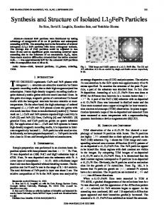
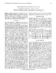
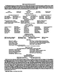
requirements and to the number of ICCG iterations. For the mesh CM1 there were 67068 nonzero entries in the matrix and 73 ICCG iterations for the complete gauge and 71940 entries and 72 iterations for the incomplete gauge formulation. For the mesh CM2 399754 nonzero entries and 152 ICCG iterations for the complete gauge and 424433 and 153 for the incomplete gauge. So, in the sequence, we will present results only for the incomplete gauge formulation and no more for the complete gauge. The variation on the three components of B along the line y = z = 12.5 mm, x : 0 3 60 mm are shown in Fig. 2 for the mesh CM1 and in Fig 3 for the mesh CM2. In these figures, the results for the reference (scalar potential with the fine mesh), for the A-method without gauge, with the Coulomb gauge and with the incomplete A.w = 0 gauge are shown. In Fig. 2 it can be seen that the better approximations are obtained with the ungauged and the incomplete gauged formulations, which are nearest to the reference. With the Coulomb gauge, the flux density inside the iron is much smaller than the reference, a behavior already detected in [ll. For the mesh CM2 which is finer than CM1, the approximation obtained with the Coulomb gauge becomes better, but it is still worse than the other two A-based methods. With the incomplete gauge formulation it is possible to obtain a better precision than with the Coulomb gauge for the same mesh, and even with the coarser mesh CM1 better results are obtained than with the fine mesh CM2 and the Coulomb gauge. This can be seen if the results in Fig. 2 are compared to the results in Fig. 3. The price to be paid for this better approximation is a higher number of ICCG iterations. From this, it can be concluded that the incomplete gauge is more favorable than the Coulomb gauge if the precision and the number of unknowns are taken into account, and is more favorable than the ungauged formulation if the number of unknowns and the system matrix condition number are taken into account. IV. CONCLUSIONS
......C oulomb gauge Ungsuped incomplete gauge
1.0 ' . 5 m .5 .....__...._ ...'.
0
incompleta gauge scalar Potantia~
121
141 0
.
5
j
,
151
0.04 -2.5
j 0
161
,
I
20
x (mm) 40
I
60
Fig.2. Components of B along the line y = z = 12.5 mm for the mesh CM1 (1440 brick elements)
'
i
60
better than the Coulomb gauge and is similar to ungauging. From the viewpoint of computer-time it is better than the ungauged method and worse than the Coulomb gauge method. From the viewpoint of memory requirements it is better than the other two methods. Then, the incomplete gauging is a good option for improving the results obtained with an A-based method without a high computational effort.
[31
-
I
40
Fig. 3. Components of B along the line y = z = 12.5 mm for the mesh CM2 (8000 brick elements)
111
.----Ungauged .......Coulomb-gaUge
I
20
x (mm)
The method of incomplete A.u = 0 gauging was developed for nodal A-based 3-D magnetostatic computations. From the viewpoint of the precision in the magnetic flux density computations, this gauge is
Bx (T)
I
0
[71
REFERENCES K. Preis, I. Bardi, 0. Biro, C. Magele, U. Renhart, K.R. Richter and G. Vrisk: "Numerical analysis of 3D magnetostatic fields", The Fourth Biennial IEEE Conf. on Electr. Fields Computation, Paper BA-01, Toronto, Canada, October, 1990. N.A. Demerdash, T.W. Nehl, F.A. Fouad and O.A. Mohammed: "Three dimensional finite element vector potential formulation of magnetic field in electrical apparatus", IEEE Transactions on Power Apparatus and Systems, Vol. 100, No.8, August 1981, pp. 4104-4111. S.R. Hoole, R. Rios and S. Yoganathan "Vector potential formulations and finite element trial functions", International Journal for Numerical methods in Engineering, Vol. 26, 1988, pp.95-108. J. Rikaby, C.F. Bryant and E.M. Freeman. "On the solvability of magnetostatic vector potential formulations", IEEE Transactions on Magnetics, Vol. 26, No.5, September 1990, pp. 2866-2874. N.A. Demerdash and R. Wang. "Theoretical and numerical difficulties in 3-D vector potential methods in finite element magnetostatic computations", IEEE Transactions on Magnetics, Vol. 26, No. 5, September 1990, pp. 1656-1658. J.L. Coulomb: "Finite element three dimensional magnetic field computation", IEEE Transactions on Magnetics, Vol. 17, 1981, pp. 3241-3246. C.J.Carpenter, "Comparison of alternative formulations of 3- dimensional magnetic-field and eddy-current problems at power frequencies". Proc.
Authorized licensed use limited to: UNIVERSIDADE FEDERAL DE MINAS GERAIS. Downloaded on August 19, 2009 at 11:38 from IEEE Xplore. Restrictions apply.
1047 IEE, Vol. 124, No. 11, November 1977, pp. 1026-1034. IS] R. Albanese , G. Rubinacci, "Magnetostatic field computations in terms of two-component vector potentials", International Journal for Numerical methods in Engineering, Vol. 29, 1990, pp. 5 15-532. [9J M. L. Brown, "Calculation of 3-dimensional eddy currents at power frequencies", IEE Proc., Vol. 129, No. 1, January 1982, pp. 46-52. [lo] K. Fujiwara, T. Nakata, N. Takahashi, T. Imai: "Effects of gauge condition on accuracy and CPU time for 3-D finite-element method using edge element", The Fourth Biennial IEEE Conference on Electromagnetic Field Computation, Paper CA-10, Toronto, Canada, October, 1990.
'
Authorized licensed use limited to: UNIVERSIDADE FEDERAL DE MINAS GERAIS. Downloaded on August 19, 2009 at 11:38 from IEEE Xplore. Restrictions apply.