Apr 4, 2013 - We present the experimental results of femtosecond slicing an ultrarelativistic, ... be similarly implemented without significant cost or design.
PHYSICAL REVIEW SPECIAL TOPICS - ACCELERATORS AND BEAMS 16, 042801 (2013)
Electron slicing for the generation of tunable femtosecond soft x-ray pulses from a free electron laser and slice diagnostics S. Di Mitri, D. Castronovo, I. Cudin, and L. Fro¨hlich Elettra-Sincrotrone Trieste S.C.p.A., 34149 Basovizza, Trieste, Italy (Received 3 October 2012; published 4 April 2013) We present the experimental results of femtosecond slicing an ultrarelativistic, high brightness electron beam with a collimator. In contrast to some qualitative considerations reported in Phys. Rev. Lett. 92, 074801 (2004), we first demonstrate that the collimation process preserves the slice beam quality, in agreement with our theoretical expectations, and that the collimation is compatible with the operation of a linear accelerator in terms of beam transport, radiation dose, and collimator heating. Accordingly, the collimated beam can be used for the generation of stable femtosecond soft x-ray pulses of tunable duration, from either a self-amplified spontaneous emission or an externally seeded free electron laser. The proposed method also turns out to be a more compact and cheaper solution for electron slice diagnostics than the commonly used radio frequency deflecting cavities and has minimal impact on the machine design. DOI: 10.1103/PhysRevSTAB.16.042801
PACS numbers: 41.85.Si, 29.20.Ej, 29.27.Eg, 41.60.Cr
I. ELECTRON SLICING WITH A COLLIMATOR In response to the interest of the community of synchrotron radiation and free electron laser (FEL) users in ever shorter x-ray pulses [1,2] and flexible parameters of the output photon beam [3,4], we propose an electron beam collimation system for the generation of femtosecond soft x-ray pulses with tunable duration from a free electron laser. We demonstrate that the beam collimation is compatible with the machine operation both in terms of radiation dose production and beam diagnostics, i.e. trajectory control in the beam delivery system. Measurements of the beam slice optical parameters supported by an analytical evaluation, demonstrate that the collimator transverse wakefield does not degrade the emittance of the collimated beam, which can therefore be devoted to FEL production as well as to slice diagnostics. Similarly to the work presented in [5], the method relies on the linear correlation between the particle energy and its longitudinal coordinate along the bunch established via upstream off-crest radio frequency (rf) acceleration. Such a beam manipulation is regularly implemented in modern linac-based FELs for bunch length compression in a magnetic chicane, in order to increase the electron bunch peak current and eventually enhance the FEL process [6–8]. In the following, we only consider the particle motion in the chicane bending plane. We propose to install a collimator at the center of the chicane. If, at that p location, the momentum dispersion is ffiffiffiffiffiffiffi much larger than "�=�� , where " is the beam rms geometric emittance, � is the betatron function, and ��
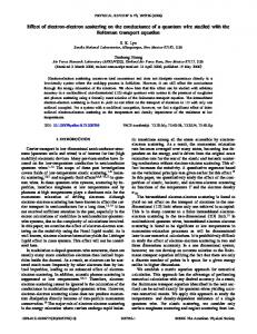
is the rms relative energy spread, the beam size is dominated by the particle momentum dispersion and the collimator selects a longitudinal slice of the bunch. The proposed method is sketched in Fig. 1. It has the same advantage of simplicity and flexibility as in [5], and it can be similarly implemented without significant cost or design alterations to an existing machine. However, it crucially differs from [5] in that only the selected slice is propagated downstream of the chicane, while the rest of the beam is partially absorbed and scattered by the collimator and is finally lost in the chicane vacuum chamber. The particle removal allows slice diagnostics, since the beam slice is the collimated beam itself. After propagating the collimated beam in dedicated insertions, its horizontal, vertical, and longitudinal parameters can be measured with standard diagnostics. This is a much more compact and cheaper solution than the commonly used rf deflectors [9,10]. When the accelerator is set for beam production, the collimated beam can be used for the generation of femtosecond soft x-ray FEL pulses with tunable duration, either from a self-amplified spontaneous emission (SASE) FEL [11,12], or from an externally seeded FEL [13–18]. Unlike in [5], no corruption from spoiled electrons would degrade the FEL output. The method is also likely to ensure a good FEL stability [19], since a seeding pulse longer than the collimated beam would make the FEL scheme less sensitive to the arrival time jitter of the electron beam, while the collimator, acting like a monochromator, reduces the effective beam mean energy jitter. The tunability of the final bunch duration, namely the slice length and the FEL pulse duration, depends on the minimum step of the movement of the collimator blades. Making use of [5] [Eq. (2)],
Published by the American Physical Society under the terms of the Creative Commons Attribution 3.0 License. Further distribution of this work must maintain attribution to the author(s) and the published article’s title, journal citation, and DOI.
1098-4402=13=16(4)=042801(5)
042801-1
�tFWHM �
2�x � ; �x t;f
(1)
Published by the American Physical Society
DI MITRI et al.
Phys. Rev. ST Accel. Beams 16, 042801 (2013)
FIG. 1. Schematic top view (not to scale) of electron slicing with a collimator placed in the middle of a magnetic chicane, once a linear energy chirp is imparted to the electron beam by an upstream accelerator.
we find that a 1 �m step with submicron reproducibility, which is available from commercial linear encoders, results in a control of the final bunch length with subfemtosecond accuracy. In Eq. (1) we used the following notation: �tFWHM is the full-width-half-maximum (FWHM) duration of the collimated beam, �x is the collimator halfaperture, �x is the rms beam size at the collimator that includes the particle chromatic motion, and �t;f is the final rms bunch duration after the chicane, if the collimator were removed. II. EXPERIMENTAL RESULTS The feasibility and operability of the proposed method was investigated in the linear accelerator of FERMI@Elettra FEL [8]. The collimator is a horizontal scraper made of two identical, cylindrical and individually movable rods of copper. The rod diameter is 13 mm wide. The thermal load of the scraper was simulated with the code ANSYS WORKBENCH V13.0 SP2 [20] under the assumption of a 500 pC, 1 ps long electron bunch that is impinging on the scraper rod at the mean energy of 300 MeV and at the repetition rate of 50 Hz. The average beam power is only 7.5 W. The beam is assumed to cover a surface of 15 � 1 mm2 , on account of the fact that the beam is stretched in the horizontal plane during compression.
Water cooling of the blade with a flux of 650 liter=hour (water velocity of 2:05 m=s) is taken into account. The code predicts a maximum temperature of 698� C on the rod’s surface in the transient regime, while in the steady-state regime, with a constant heating flux, the surface temperature reaches 24� C. In both regimes, the water temperature increment is only 0:014� C. The radiation dose in the machine area surrounding the magnetic chicane (BC1) was measured when approximately 95% of the 500 pC beam had been intercepted by the scraper blades. The remaining 5% was passing through a 100 �m aperture and detected a few meters downstream. We measured a dose rate of about 80 Gy=h on the vacuum chamber about half a meter downstream of the scraper and 4 Gy=h on the electronics (specifically, a screen system) in its vicinity. To avoid radiation damage, a relocation of such electronics or the installation of shielding needs to be evaluated. There was no measurable dose rate (< 0:1 Gy=h) on the electronics placed at the end of the chicane. No deterioration of the vacuum was measurable during the experiments. Collimation for slice diagnostics was applied to an initial 350 pC, 5 ps long beam. The magnetic chicane and the upstream linac were set in order to define the bunch length compression by a factor of 5.5. All the relevant beam and machine parameters are listed in Table I. The geometric beam size in the middle of BC1 was �� ¼ 160 �m so, following the prescription in [5] [Eq. (1)], the scraper blades were inserted into the vacuum chamber to define a half-aperture at least 3 times bigger, namely 0.5 mm wide. The chromatic beam size �x ¼ 2:6 mm was much larger than the geometric one, so we can use Eq. (1) to evaluate the duration of the collimated beam that is �tcol � 70 fs FWHM. The charge of such a beam is expected to be col Qcol ¼ Qi C�t �ti � 27 pC, where Qi and �ti are, respectively, the initial total charge and the initial bunch duration (FWHM) and C is the compression factor. The scraper aperture was consecutively translated to select 12 longitudinal slices of the bunch. Each slice was accelerated and transported to the linac end, in the so-called transfer-linestraight (TLS) region. The initial response of the beam
TABLE I. Electron beam and machine parameters used during beam collimation for slice diagnostics. The optical parameters were measured at the entrance of the quadrupole used for the emittance measurement. Parameter Charge Mean energy Energy spread, rms Normalized projected emittance, rms � function � function Dipole bending angle Central momentum dispersion Compression factor
In BC1
In TLS
Units
350 303 1.0 1.7 (H), 1.3 (V) 22.2 (H), 24.1 (V) 9.3 (H), �3:1 (V) 85 255 5.5
10–35 1205 0.3 3.7 (H), 1.9 (V) 9.4 (H), 8.2 (V) 4.5 (H), �3:9 (V)
pC MeV % mm mrad m
042801-2
mrad mm
ELECTRON SLICING FOR THE GENERATION OF . . .
Phys. Rev. ST Accel. Beams 16, 042801 (2013)
position monitors (BPMs) to the smaller charge was different by up to 100’s micron with respect to the entire beam. However, the feedback was able to restore the reference trajectory in a few shots: a clear demonstration that a minimum charge of �10 pC can be steered along the beam line with a few microns accuracy. The slice optical parameters were measured both in the BC1 and in the TLS region with the quadrupole scan technique [21,22], in dedicated diagnostic stations. The impact of the scraper transverse wakefield on the emittance of the collimated beam was analytically estimated, with the limitation that the model starts failing when the particles travel at a distance comparable to the collimator half-aperture. Following [23], the FERMI scraper behaves like a flat, long collimator and the kick factor � must be computed in the diffractive regime. For a half-aperture 0.5 mm wide, we have � ¼ 72 V=pC=mm. This is a rather large value but its effect on the emittance is mitigated by the low charge traversing the scraper and a proper optics setting at the collimator location. In the case of a 50 pC beam charge traveling 0.4 mm far from the scraper axis, the collimator’s kick is [23] � ¼ hQ� E ¼ 4:8 �rad, where Q is the bunch charge, h is the bunch centroid distance from the collimator axis, � is the kick factor in the plane of interest, and E is the beam mean energy. Following [24], the normalized emittance growth can be estimated with sffiffiffiffiffiffiffiffiffiffiffiffiffiffiffiffiffiffiffiffiffiffiffiffiffiffiffiffiffiffiffiffiffiffiffi � � � �"x ¼ � "2x;0 1 þ x �2 � 0:07 �m; (2) "x;0
where � is the relativistic Lorentz factor, �"x;0 � 1 �m is the unperturbed rms geometric emittance, and �x is the horizontal betatron function at the collimator location. Its design value for a matched beam is 3 m. In Eq. (2), we considered the case of a reasonably mismatched beam, i.e. �x ¼ 10 m. We do not expect any effect in the vertical plane because the collimator has no aperture restrictions in that plane. Figure 2 shows the slice distribution of the charge, the emittance, and the Courant-Snyder (C-S) parameters [25] measured in BC1 and in TLS. The quadrupole scan technique and measurement accuracy are discussed, e.g., in [22]. The largest error bars for the emittance measurement are dominated by the variation of the central value over several consecutive measurements. This variation is mainly addressed to imperfect background subtraction during the beam image recording. The maximum error over all measurements is considered for the C-S parameters. By comparing the optics parameters of the entire beam, listed in Table I, with those of Fig. 1, we infer that the slice emittance after collimation is typically equal or smaller than that of the whole beam, and that the scraper wakefield does not degrade the emittance of the collimated beam. Moreover, the slice emittance is approximately preserved during the beam transport from BC1 to TLS, while the projected emittance in TLS is larger than in BC1. This is an indication that it is dominated by the correlation of the slices’ centroid coordinates in the transverse phase space, such as those induced by linac geometric wakefields [26].
nx
25
40
βx(TLS) β (BC1) Charge
1.5 1.0
Charge 30
30 20 20
10
15 αx [ m ]
20
x
2.0
β [m]
2.5
20 30
40
Charge [ pC ]
30
40
αx(TLS) αx(BC1)
x
nx
Charge 3.0
Charge [ pC ]
Horiz. Norm. Emitance [ mm mrad ]
50
ε (TLS)
20 10
Charge [ pC ]
40
ε (BC1) 3.5
10
10 5
10 0.5
−2
0
2
4
0 −6
6
−4
Scraper center position [ mm ]
2
4
0 −6
6
−4
1.5
40
−2 30
30
30 20 20
10
1.0
6
−4 αy [ m ]
20
2.0
4
y
40
βy [ m ]
2.5
2
βy(BC1) Charge
30
0
0
40
β (TLS)
Charge 3.0
−2
Scraper center position [ mm ]
50
εny(TLS)
Charge [ pC ]
Vert. Norm. Emitance [ mm mrad ]
0
40
εny(BC1) 3.5
−2
Scraper center position [ mm ]
20 −6
10
10 −8
10
Charge [ pC ]
−4
Charge [ pC ]
−6
Charge αy(TLS)
0.5
α (BC1) y
−6
−4
−2
0
2
Scraper center position [ mm ]
4
6
0 −6
−4
−2
0
2
Scraper center position [ mm ]
4
6
−10 −6
−4
−2
0
2
4
6
Scraper center position [ mm ]
FIG. 2. Charge (squares) and slice optical parameters measured in the FERMI BC1 (dots, dashed line) and TLS (dots, solid line) linac regions. From left to right: normalized emittance, � function, � function. The top line is for the horizontal plane; the bottom line is for the vertical.
042801-3
DI MITRI et al.
Phys. Rev. ST Accel. Beams 16, 042801 (2013) 4
150
104
Power ∆t FWHM
2
10
3.5
100
Power [GW]
10
∆t FWHM [fs]
Power [MW]
103
3
50 1
0.1 0
5
10 z [m]
15
20
0
100 200 300 400 500 600 700 800 900 1000 ∆x [µm]
2.5
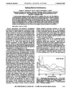
FIG. 3. Left: FEL peak power along the FERMI high gain harmonic generation undulator line for 80 pC, 110 fs long electron bunch. Different colors along the curve correspond to the emission of different and consecutive undulator segments. Right: FEL final pulse duration FWHM (solid line) and peak power (dashed line) versus the collimator half-aperture. Simulations were performed with the code PERSEO.
III. FEL SIMULATION The simulation of a SASE FEL is not of great interest here since it has already been treated in [5] and, as previously explained, the collimated beam exiting the chicane has the same properties of the unspoiled beam in the foil scheme. We focus instead on the performance of a seeded FEL. We simulated the FERMI high gain harmonic generation [8,13,14] with the code PERSEO [27]. The undulator line consists of one longer period undulator (called modulator) for electron beam and seed laser interaction, a dispersive section (R56 ¼ �40 �m) for bunching enhancement, and six identical shorter period undulators (called radiators) in the planar horizontal configuration. The seed laser delivers 100 MW of peak power at 266 nm wavelength in a flat, 350 fs long pulse. The radiators are tuned to the tenth harmonic of the seed laser, i.e. to a wavelength of 26.6 nm. We chose electron beam parameters that reflect the most recent FERMI performance [8]: a 500 pC, 10 ps long electron beam is assumed to be compressed by a factor 15 in BC1 to achieve a flat current profile of approximately 750 A, and accelerated to the energy of 1.2 GeV. The final slice emittance is 1.0 mm mrad and the slice energy spread is 150 keV. We assume the collimator setting adopted for the aforementioned slice diagnostics experiment. The FWHM duration of the collimated beam turns out to be [5] �tcol � 110 fs, carrying a charge pffiffiffiffiffiffi Qcol � 80 pC. We note that �tcol and Qcol scale as �x in the middle of the chicane, i.e. a 10 times smaller �x would allow the generation of a 25 pC, 35 fs long collimated beam. The FEL power emitted by the 80 pC bunch along the undulator is shown in Fig. 3. The final peak power is 3 GW over 38 fs (FWHM), which corresponds to � 2 � 1013 photons=pulse. The final FEL pulse duration is also shown as a function of the
collimator half-aperture in BC1. The maximum peak power decreases from 3.71 to 2.98 GW (not shown) as the photon pulse shrinks from 120 to 16 fs (FWHM). IV. CONCLUDING REMARKS In summary, the proposed beam collimation system offers an alternative way to diagnose slice properties of an electron bunch, with minimal impact on the machine configuration. A comparison of the performance of proposed scheme with other established techniques, such as rf deflecting cavities, is already in the authors’ plan and will be faced in a dedicated work. The proposed scheme extends the capability of a soft x-ray FEL facility to generate stable femtosecond pulses with tunable duration driven either by SASE or an external seed laser. It is not straightforward to extend the proposed method to the generation of subfemtosecond pulses as well as to hard x-ray FELs as both these scenarios would imply an electron charge at the level of a few pC in the delivery system. Electron beam diagnostics like BPMs might be appositely tuned to handle such a small signal level. We note, however, that a very low charge option is already on the horizon of existing and planned FEL facilities [28–31], thus anticipating a fundamental step forward for linacbased, short pulse FELs in the near future. ACKNOWLEDGMENTS The authors acknowledge L. Giannessi for the guidance to the code PERSEO and M. Cornacchia for the careful reading of this article and numerous suggestions.
042801-4
ELECTRON SLICING FOR THE GENERATION OF . . .
Phys. Rev. ST Accel. Beams 16, 042801 (2013)
[1] L. B. Da Silva, J. E. Trebes, R. Balhorn, S. Mrowka, E. Anderson, D. T. Attwood, T. W. Barbee, J. Brase, J. Corzett, J. Gray, J. A. Koch, C. Lee, D. Kern, R. A. London, B. J. MaxGowan, D. L. Matthews, and G. Stone, Science 258, 269 (1992). [2] R. Neutze, R. Wouts, D. van der Spoel, E. Weckert, and J. Haidu, Nature (London) 406, 757 (2000). [3] B. C. Garrett, Science 303, 1146 (2004). [4] E. Allaria, C. Callegari, D. Cocco, W. M. Fawley, M. Kiskinova, C. Masciovecchio, and F. Parmigiani, New J. Phys. 12, 075002 (2010). [5] P. Emma, K. Bane, M. Cornacchia, Z. Huang, H. Schlarb, G. Stupakov, and D. Walz, Phys. Rev. Lett. 92, 074801 (2004). [6] P. Emma et al., Nat. Photonics 4, 641 (2010). [7] W. Ackermann et al., Nat. Photonics 1, 336 (2007). [8] E. Allaria et al., Nat. Photonics 6, 699 (2012). [9] M. Ro¨hrs, C. Gerth, H. Schlarb, B. Schmidt, and P. Schmu¨ser, Phys. Rev. ST Accel. Beams 12, 050704 (2009). [10] S. Ahmed, G. A. Krafft, K. Deitrick, S. U. De Silva, J. R. Delayen, M. Spata, M. Tiefenback, A. Hofler, and K. Beard, Phys. Rev. ST Accel. Beams 15, 022001 (2012). [11] R. Bonifacio, C. Pellegrini, and L. Narducci, Opt. Commun. 50, 373 (1984). [12] A. M. Kondratenko and E. L. Saldin, Part. Accel. 10, 207 (1980). [13] L. H. Yu, Phys. Rev. A 44, 5178 (1991). [14] L. H. Yuet al., Science 289, 932 (2000). [15] G. Stupakov, Phys. Rev. Lett. 102, 074801 (2009). [16] J. Feldhaus, E. L. Saldin, J. R. Schneider, E. A. Schneidmiller, and M. V. Yurkov, Opt. Commun. 140, 341 (1997). [17] G. Geloni, V. Kocharyan, and E. L. Saldin, J. Mod. Opt. 58, 1391 (2011). [18] G. Lambert et al., Nat. Phys. 4, 296 (2008).
[19] S. Di Mitri et al., Nucl. Instrum. Methods Phys. Res., Sect. A 608, 19 (2009). [20] http://www.ansys.com/Products/ANSYS+13.0+Release +Highlights. [21] M. G. Minty and F. Zimmermann, Report No. SLAC-R621, 2003. [22] S. Di Mitri, E. M. Allaria, P. Craievich, W. Fawley, L. Giannessi, A. Lutman, G. Penco, S. Spampinati, and M. Trovo’, Phys. Rev. ST Accel. Beams 15, 020701 (2012). [23] P. Tenenbaum, K. L. F. Bane, L. Eriksson, J. Irwin, R. K. Jobe, D. McCormick, C. K. Ng, T. O. Raubenheimer, M. C. Ross, G. Stupakov, D. Walz, D. Onoprienko, and I. Zagorodnov, Phys. Rev. ST Accel. Beams 10, 034401 (2007). [24] S. Di Mitri, L. Fro¨hlich, and E. Karantzoulis, Phys. Rev. ST Accel. Beams 15, 061001 (2012). [25] E. D. Courant and H. S. Snyder, Ann. Phys. (N.Y.) 3, 1 (1958). See also S. Y. Lee, Accelerator Physics (World Scientific Publishing Co., Singapore, 2007, ISBN-13 978981-256-182-4. [26] P. Craievich, S. Di Mitri, and A. A. Zholents, Nucl. Instrum. Methods Phys. Res., Sect. A 604, 457 (2009). [27] L. Giannessi, in Proceedings of the 28th Free Electron Laser Conference (Berlin, Germany, 2006), p. 91, http:// www.afs.enea.it/gianness/perseo/. [28] Y. Ding et al., Phys. Rev. Lett. 102, 254801 (2009). [29] S. V. Benson, D. R. Douglas, P. Evtushenko, F. E. Hannon, C. Hernandez-Garcia, J. M. Klopf, R. A. Legg, G. R. Neil, M. D. Shinn, C. D. Tennant, S. Zhang, and G. P. Williams, J. Mod. Opt. 58, 16 (2011). [30] Swiss FEL Conceptual Design Report, edited by R. Ganter, PSI Bericht (2010) [http://www.psi.ch/swissfel/ HomeEN/SwissFEL_CDR_web_small.pdf ]. [31] J. B. Rosenzweig et al., Nucl. Instrum. Methods Phys. Res., Sect. A 593, 39 (2008).
042801-5