2012 Sixth International Conference on Sensing Technology (ICST)
Electronic Control Sensors Applications for the Next Generation Tractor Based on Open Source Library Md. Mostafa Kamal Sarker1, Dong Sun Park2 and Luubaatar Badarch3 1-3
Division of Electronic Engineering, Chonbuk National University Jeonju-si, Jeonbuk, Republic of Korea 2 IT Convergence Research Center, Chonbuk National University Jeonju-si, Jeonbuk, Republic of Korea 1
[email protected],
[email protected],
[email protected]
ECUs connected with CAN-bus (CAN-bus is an ISO standard computer network protocol and bus standard, designed for microcontrollers and devices to communicate with each other without a host computer) and exchanging data between control units take place on a uniform platform .This platform is called a protocol. The CAN bus performs as a self-styled data highway. This topology of controller area network originally developed by Robert Bosch GmbH [2] in the early 1980s and publicly released in 1986 to replace the large amount of cabling in automobiles.
Abstract—The present agricultural machineries work with the embedded electronics and remote sensing devices. This paper presents the development of electronic control sensors applications for the next generation agricultural tractor. This development work is mainly based on an open source library which follows an International Organization for Standardization (ISO) standard named ISO11783. The ISO11783 standard (also known as ISOBUS) specifies a communication system for agricultural and forestry machineries based on Controller Area Network (CAN 2.0) protocol, and the principle of this standard is to provide an open, interconnected system for on-board electronic systems. It’s planned to allow electronic control units (ECUs) for communicating with all other on CAN bus, provided that a uniform system. The open source library applications are written by C/C++ programming method for developing tractor ECUs. This research work mainly describes the system architecture of this ISO11783 based open source library and developing application program of virtual terminal and some electronic control unit(ECU) for agricultural tractor.
This research explains some development of tractor electronic control systems and gives some idea about an open source library named “ISOAgLib”[3] with software environment. In our research work, we developed virtual terminal (VT) for a tractor which follows the standard part of ISO11783-6[4] and also ECU Data Source, ECU Display, ECU GPS Sensor, ECU Tractor Bridge. Firstly, for developing VT we use S3C6410 32-bit RISC microprocessor and its working environment is embedded operating system Windows Embedded CE 6.0(WinCE 6.0). Secondly, for developing ECUs we chose our test board is STM32F107 ARM 32-bit Cortex-M3 board for ECUs hardware. Thirdly, the programming environment is Windows Visual Studio 2005. Finally, following the standards and open source library system architecture we developed our electronic control systems for tractor. This paper is organized as follows: In section II, III, IV, V, VI, VII and VIII, we have described ISO11783, structure of tractor electronic control system, controller area network, ISOAgLib an open source library, test environment, application program design, experimental results and discussion, respectively. Finally, Conclusions are presented in section IX.
Keywords- ISO 11783; electronic control system; controller area network; open source library and application program
I.
INTRODUCTION
The field of developing agricultural machinery equipments is very important. The needs of agricultural goods are increasing day by day over the world and for this reason it is very important to develop agricultural tractor electronic control systems for providing a great amount of agricultural goods with low cost and least time. Development of automobiles has been started before many years but the developments of electronic control system of agricultural vehicles have been started before few years when ISO provide some standard for tractors and machinery for agriculture and forestry-serial control and communications data network. This standard name is ISO11783 and it has 13 parts. At the present time, producers of agricultural equipments have progressively turned to electronics for supplying products with superior functionality, performance and productivity to customers. An ordinary result of adding electronic tools to agricultural machinery has understood the advantages of permitting the mechanism to communicate with each other. Developing the electronic control systems, a lot of ECUs interconnected inside agriculture tractor [1]. Such as ECU Data Source, ECU Display, ECU GPS Sensor, ECU Tractor Bridge, etc. All
978-1-4673-2248-5/12/$31.00 ©2012 IEEE
II.
ISO 11783
From late 1980’s, the improvement of communication network between tractor and implements was initially started in Germany. In that time, German institute for standardization (Deutsches Institut für Normung) gives a standard for tractor communication network named DIN9684. The main part of DIN was completed in the end of 1991. At the same time, similar standard made by Society of Automotive Engineers in United States named SAE J1934. Since 1992 a new standard
486
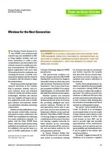
for agricultural machine communication has been developed by International Organization for Standardization (ISO) standard named ISO11783. This Standard is sometimes called as ISOBUS [5]. It consists of several parts: general standard for mobile data communication, physical layer, data link layer, network layer, network management, virtual terminal, implement messages applications layer, power train messages, tractor ECU, task controller and management information system data interchange, mobile data element dictionary, diagnostic and file server. The architecture of electronic data communication of ISO 11783 is based on the open system interconnect (OSI) model layers, however, the advanced functional layers sometimes defined in a different way. Figure 1 schematically illustrates the layer stricter ISO 11783 standard. Controller Transmitter
Application
Network
Data Link Logical Link Control (LLC)
Data Link Medium Access Control (MAC)
Key PF PDU Format R Reserved DP Data Page SA Source Address PS PDU Specific
Priority, EDP, DP, PF, PS, SA, Data
Priority, EDP, DP, PF, PS, SA, Data
1 or more PDU
1 or more PDU
1 or more CAN Message
1 or more CAN Message
Physical
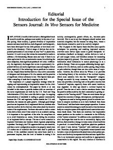
current torque curve for transmission gearbox, and so on. The ECU of the tractor functions as a filter for message transport between the tractor bus and the equipment bus, which can avoid the event that the communication task of one bus is so heavy that the other bus is overloaded. Figure 2 illustrates the structure of tractor electronic control system installed in agricultural tractors and implements.
Controller Receptor
Figure 2. Structure of tractor electronic control system
Application
IV.
Controller Area Network or CAN (CAN-bus) is an ISO standard (computer network protocol) and bus standard, which is intended for all devices and microcontrollers to communicate with every other without a host computer. It was proposed for industrial networking but lately more customized to automotive applications, CAN have gained extensive fame for embedded control in the fields of mobile machines, industrial automation, automotives, medical, military and other harsh background network applications.
Network
Data Link Logical Link Control (LLC)
Data Link Medium Access Control (MAC)
A. CAN interface in embedded systems The Controller Area Network or CAN (CAN-bus) is a broadcast category of bus. That means there is no unequivocal address in the messages. Each node in the network is capable to pick-up or receives every transmission. There is no technique to transmit a message to a specific node. All messages bring a numeric value, which controls its precedence on the bus, and may also serve as recognition of the contents of the message. If the message is applicable, it will be processed; otherwise it ignored. If the bus is free, any node may begin to transmit. But what will occur in those events where two or more nodes try to transmit messages (to the CAN bus) at the same time. The identifier field is unique during the network assists to determine the priority of the message. To ensure that the messages are transmit in order of priority and that no messages are lost, a "non-destructive arbitration technique" is utilized to do this. The lower numerical value of the identifier is higher priority. That signify the message with identifier having more dominant bits (i.e. bit 0) will overwrite by other nodes' with less dominant identifier so that ultimately (after the arbitration on the identifier) only the dominant message remains and is received by every nodes. As described in previous, CAN do not exploit address-based format for communication, as an alternative uses a messagebased data format. Here the message is transmitted from one location to another by sending a collection of bytes at once (based on the order of priority). Usually the major processor
Physical
Figure 1. Application of OSI Model according to ISO 11783
III.
CONTROLLER AREA NETWORK
STRUCTURE OF TRACTOR ELECTRONIC CONTROL SYSTEM
Modern implements and tractors have many functions that are automated or electronically controlled. Today agricultural machines consequently depend on at least single onboard computer. The tractor electronic control system is consisting of at least two bus-systems, tractor bus and implements bus. Tractor bus is used for communication between each functional component of the tractor, while implement bus is used for communication between each additional functional equipment installed in the tractor (such as, virtual terminal, task controller and management computer interface), and for communication between each ECU of agricultural implement. Task controller is used to issue instructions to different equipment to complete some task. And management computer interface is used for data exchange between task controller and external management computer. Communication is realized between different equipment in the bus network by way of sending messages, and its typical application is as follows: task controller in real time receives information of navigation and location generated by GPS, the ECU of the engine provides its
487
will be the engine control unit or the host processor. The CAN standard even assists the subsystem to manage actuators or obtain signals from sensors. A CAN message never arrive at these devices directly, except instead a host-processor and a CAN Controller (by a CAN transceiver) is necessary among these devices and the bus. The CAN Controller supplies received bits (separately) from the bus until a complete message block is available, then that can be obtained by the host processor (generally after the CAN Controller has triggered an interrupt). The Can transceiver adapts signal levels from the bus, to levels that the CAN Controller expects and also provides a protective circuitry for the CAN Controller. The host-processor chooses what the arriving messages mean and which messages it needs to transmit itself)Abbreviations such as IEEE, SI, MKS, CGS, sc, dc, and rms do not have to be defined. Do not use abbreviations in the title or heads unless they are unavoidable.
information provided via the application layer. They are Priority, Data Page, Data Fields, Reserved, PDU Format, PDU Specific (which can be a Group Extension, proprietary or destination address) and Source Address. After that they are enclosed into one or more CAN data frames and transmitted over the physical media to other network controllers. The layers of the OSI model that ISO 11783 supports are shown in figure 1. It should be recognised that some Parameter Group definitions require more than one CAN data frame to send their information. According to ISO 11783, an entire explanation for every of the bit field assignments is specified in Protocol Data Unit (PDU) formats [7]. V.
ISOAGLIB AN OPEN SOURCE LIBRARY
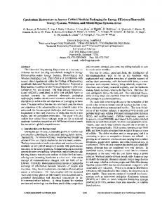
For the development of VT and ECUs Applications, we use an open source programming library named ISOAgLib. The IsoAgLib is a C++ library in development of ISO 11783 standard applications in an Object Oriented way to serve as a software layer between application specific program and communication protocol details. The author of IsoAgLib library, Dipl. - Inform. Achim Spangler, licensed with exceptions under the terms of the GNU General Public License (GPL). By providing simple function calls for jobs like starting a measuring program for a process data value on a remote ECU, the main program has not to deal with single CAN message formatting. This way communication problem between ECU's which use this library should be prevented. The IsoAgLib has a modular design pursuant to the various functional components of the standard ISO 11783. The library has this design to make sure the minimum use of IsoAgLib in program memory of Implement ECU. The IsoAgLib demonstrates the layered architecture to be easily familiar with new hardware platforms. Most of the software can be used without alteration on all platforms. The layered architecture is described by the diagram in Figure 5.
Figure 3. CAN interface in embedded systems
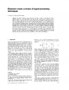
B. CAN Message frame format The implementation of the CAN message for tractors and machinery for agriculture is based on CAN Version 2.0B [6]. This describes a 29-bit identifier and a data rate of 250 kbit/s. There are two types of CAN message frame format for the data receiving and transmitting available are: a) CAN Standard frame format b) CAN Extended frame format
Figure 5. System architecture of open source library
The IsoAgLib was developed to be suitable with different systems, and these systems can be an element of processor, memory, Human Machine Interface (HMI) and interface with the CAN bus. Therefore, the IsoAgLib is divided into two sections: the library itself and HAL. The HAL is responsible for communicating with the operating system (OS) or BIOS device that is running the application, as can be seen in Figure 5. We implement CAN-bus is real-time operating system. The application program initialized CAN controller and accessing CAN-bus.
Figure 4. CAN Data Frames
The CAN extended frame message, as shown in figure 4, encompasses a single Protocol Data Unit (PDU). PDUs consist of seven pre-defined fields. These areas are assimilated since
488
VI.
produced by STMicroelectronics company of French-Italy. It is a totally integrated mixed-signal system-on-chip, which integrates in one chip almost all the analog peripherals, digital peripherals and other functional components that are necessary to form a data sampling or control system of a SCM. BOTSH CAN controller is compatible with CAN technical specification 2.0A and 2.0B is integrated in STM32F107 and also 2.4 inch TFT LCD Panel (320*240) with touch screen. It is composed of CAN kernel with 256KB Flash and 64KB RAM internal memory, message processing unit and register. CAN controller has 32 message destinations which can be used to send or transmit data. Received data, message destinations and identification code are storage in Message RAM. Figure 8 shows test connection configuration between working PC and test board for checking the ECU working status.
TEST ENVIRONMENT
A. Virtual Terminal(VT) For the development of VT, we use a main board is based on a 32-bit RISC (Reduced instruction set computing) Microprocessor of fixed point series-S3C6410X, which is designed to provide a cost-effective, low-power capabilities, high performance Application Processor solution for mobile phones and general applications. The features of S3C6410X microprocessor is ARM1176JZF-S based CPU subsystem with Java acceleration engine and 533MHz at 1.1V and 667MHz at 1.2V respectively, 8-bit ITU 601/656 Camera interface, 2D/3D graphics acceleration, port USB 2.0 OTG, Real-time clock, PLL, 32 channel DMA controller, Memory Subsystem, etc. It has a high-speed SPI interface that communicate CAN module which completely compliant with CAN protocol (version 2.0B). Therefore, it is suitable to understand the network communication interface among VT and ISOBUS. Moreover, it can be easy to design the LCD display, I/O and communication interface of VT. The implementation of Main board is showed in figure 6.
Figure 8. Test cconnection between working PC and test board
In this figure, test board COM1 port (i.e.name of serial port hardware for input and output) is linked with PC COM1 port for sending time acknowledgement (ACK) of CAN message to PC. In this relationship scheme, we use AMTEL mini JLINK (USB driven JTAG interface for ARM cores including mini USB cable) is an optimizing C/C++ compiler (i.e. download and debug the application program) for ARM Cortex-M3 microcontroller and attach between test board Channel1 and PC USB3 port (Universal Serial Bus). This connection is main platform of our application program development. Because of this connection download application program from PC to the microcontroller for debugging and make sure the test board becomes an ECU. CAN controller has some ports but for our test purpose we use only two ports for CAN_L and CAN_H [8] and connect with CAN analyzer. Here, we also make a connection between test PC and CAN analyzer (i.e. Real SYS CAN Pro USB device for hardware) by USB2 port through USB cable. After establishing all the connections, we can verify the CAN message status by CAN Pro Analyzer v1.0 software in PC shown in figure 9.USB1 port is for test board power supply through the USB cable.
Figure 6. Hardware configuration of virtual terminal
Our implementation system connection diagram and testing CAN bus connection with two S3C6410 Embedded board shown in figure 7.
Figure 7. Test connection diagram of experiment for VT
B. Electronic control unit (ECU) For the development of ECU, we use STM32F107 ARM Cortex-M3 board. The main board STM32F107 adopts the ARM 32-bit Cortex-M3 SCM (Single Chip Microcomputer)
Figure 9. CAN message received by ECU sensor
489
VII. APPLICATION PROGRAM DESIGN We develop application program for VT by using MFC and for ECU using C++ programming methods. The application program initialized CAN controller and accessing CAN bus. Figure 10 illustrates the flow chat for application program.
Figure 10.
Application Design Flow for VT
VIII. EXPERIMENTAL RESULTS AND DISCUSSION Our developed application program of VT working well with CAN bus based on Embedded System, it means our developing CAN device driver working with WinCE Embedded operating system and real hardware. As well as we create any CAN data to send and receive from CAN bus by using real time embedded system. Figure 11 shows the experimental result of virtual terminal window. Using our VT we can send CAN messages easily to CAN server and also received messages from CAN server without any error.
Figure 12. Experimental results of ECUs application program output window (up to down- Data Source, Display, Tractor Bridge and GPS Sensor)
Figure 11. Experimental result of virtual terminal window
490
Figure 13. Analysis of two CAN messages with ISO standatd
In our experiment, when we send CAN messages by using our VT. We can see every ECUs are sending their responses same time with CAN data. All of those CAN messages are following ISO11783 standards. For example, ECU Data source process a CAN message for sending to CAN server which ID (Identifier Bit) is 18-EA-FF-FE16(hexadecimal) means that this data have (5bit-8bit-8bit-8bit)2(binary) CAN ID and first message define by request for address claimed or request PG is 00EE0016(hexadecimal) means that first data PGN is 6092810(decimal) [9]. When ECU Data source has sent this message to ECU Tractor Bridge received this message and send acknowledgement. ECU GPS Sensor sends information about tractor current position to ECU Tractor Bridge. ECU Tractor Bridge received this message and send acknowledgement to ECU GPS Sensor. All CAN messages actions are showed by ECU Display. We can verify those CAN messages and they are followed by ISO11783 standard.
virtual terminal and electronic control units (ECUs), etc. All applications are developed by using an open source library with object oriented way. In our research result, we developed virtual terminal and some ECUs for agricultural tractor which can send and received CAN messages frequently with followed ISO11783 standards. So it works perfectly without any fault. In our future work, we are going to developed more ECUs application program for an agricultural tractor with different environments. ACKNOWLEDGMENT This work was supported in part by Brain Korea-21 and the Centre for IT Convergence Agricultural Machinery (ITAM) grant (NO. R09-6)* funded by the Ministry of Knowledge Economy, Republic of Korea. REFERENCES [1]
Figure 12 shows the applications program runtime information for every ECUs (ECU Data Source, ECU Display, ECU Tractor Bridge and ECU GPS Sensor) and Figure 13 explain only two messages with some standards. So our result shows that CAN messages follow the standards perfectly without error. So our application programs of VT and ECUs are standard applications and working very well. IX.
[2] [3] [4] [5]
CONCLUSIONS
Since the past few years, a big number of developments have happened in the field of agriculture by using information technology over the world. Some countries developing their own agricultural field by using recent information technology for this reason South Korea also started and our research team initially doing some important research work on this sector, like developed application program for agricultural tractor
[6] [7] [8] [9]
491
ISO11783-9: Tractors and machinery for agriculture and forestry -Serial control and communications data network-Tractor ECU. 2002. CAN in Automation homepage on CAN-CIA. [Online]. Available: http://www.can-cia.org. IsoAgLib: “Development of ISO 11783 applications in an Object Oriented way", [Online Available: http://isoaglib.org/], 2009. ISO11783-6: Tractors and machinery for agriculture and forestry -Serial control and communications data network-Virtual Terminal. 2002. Peter Felimeth, “CAN-based tractor- agricultural implement communication ISO 11783 [CAN Newsletter]”, 2003, 9. Bosch, Robert GmbH. “CAN Specification - Version 2.0.”, Germany, 1991. ISO11783-3: Tractors and machinery for agriculture and forestry -Serial control and communications data network-Data link layer. 1998. ISO11783-2: Tractors and machinery for agriculture and forestry -Serial control and communications data network-Physical Layer. 2002. ISO11783-5: Tractors and machinery for agriculture and forestry -Serial control and communications data network-Network management. 2002.