IEEE TRANSACTIONS ON INDUSTRY APPLICATIONS, VOL. 37, NO. 1, JANUARY/FEBRUARY 2001
247
Web Machine Coordinated Motion Control via Electronic Line-Shafting Robb G. Anderson, Andrew J. Meyer, M. Anibal Valenzuela, and Robert D. Lorenz, Fellow, IEEE
Abstract—Most current multi-axis web machine controllers are not designed to possess the inter-axis stiffness properties that were the inherent coordinating force in historical mechanically coupled “line-shafted” multi-axis web machines. As a result, these controllers cannot maintain coordination for all operating conditions. This paper presents the development of an “electronic line-shafting” control technique which serves to replicate and even improve on the historical mechanical line-shafted properties. This technique was implemented on a five-axes filament winding machine to evaluate such control during periods when the drive was in torque limit, velocity limit, or simply responding to asymmetric load-induced disturbances. The results demonstrate that the “electronic line-shafting” technique significantly improves the coordination, robustness, and overall stability of multi-axis web-handling machines subjected to realistic physical limitations. Index Terms—Motion control, relative stiffness control, synchronized control.
I. INTRODUCTION
P
RIOR TO computer control and high-performance servo drives, multi-axis machines were constructed with mechanical components that produced motion with respect to a common input. The power was produced by a single motor driving a long common "line" shaft to which all the axes were attached. As advances in computer control, power electronics, and high-performance servo drives became available, they began to evolve as programmable replacements for the line-shafted machines. Although this programmable flexibility provided enormous strides in manufacturing automation, it lost the inter-axis state feedback inherent to the line-shafted predePaper MSDAD-S 00–13, presented at the 1999 Industry Applications Society Annual Meeting, Phoenix, AZ, October 3–7, and approved for publication in the IEEE TRANSACTIONS ON INDUSTRY APPLICATIONS by the Industrial Automation and Control Committee of the IEEE Industry Applications Society. Manuscript submitted for review October 15, 1999 and released for publication August 14, 2000. This work was supported by the McClean Anderson Division of ISAMI, the Wisconsin Electric Machines and Power Electronics Consortium (WEMPEC) of the University of Wisconsin, Madison, and the Consolidated Papers Foundation. R. G. Anderson was with the McClean Anderson Division of ISAMI, Schofield, WI 54476 USA. He is now with UNICO, Inc., Franksville, WI 53126 USA (e-mail:
[email protected]). A. J. Meyer was with the McClean Anderson Division of ISAMI, Schofield, WI 54476 USA. He is now with the Genomics Institute of the Novartis Research Foundation, San Diego, CA 92121 USA (e-mail:
[email protected]). M. A. Velanzuela is with the Department of Electrical Engineering, University of Concepción, Concepción, Chile (e-mail:
[email protected]). R. D. Lorenz is with ISEA-The Power Electronics and Drives Institute, Technical university of Rhein-Westfalen, 52066 Aachen, Germany, on leave from the Department of Mechanical Engineering and Department of Electrical and Computer Engineering, University of Wisconsin, Madison, WI 53706 USA (e-mail:
[email protected]). Publisher Item Identifier S 0093-9994(01)00278-X.
cessors. This inter-axis stiffness was the driving force for the coordination of the multiple axes and its properties are not achieved by the synchronous command generation or master–slave control topologies currently in use. Most researchers in this area [1]–[4] recognize physical limitations of power conversion devices when generating command trajectories and, therefore, they focus on generating feasible high-performance trajectories. However, synchronous command generation does not recognize asymmetric loading and its ability to deteriorate synchronization. Master–slave methods similarly only force the slaved axes to follow the master. The master does not respond to symmetric loading of the slave(s). Under both of these circumstances, synchronized motion control is compromised. Such compromises are potentially very costly in web-handling process machinery since loss of synchronization (registration) can have large economic impact on the process. Lorenz and Schmidt [5] proposed a topology based on relative stiffness control which intentionally cross coupled the independent axes and emulated a line-shaft connection. This control topology was implemented and evaluated for a two-axes experimental setup and compared to synchronous command generation and master–slave control topologies. Only disturbance rejection to sinusoidal disturbance torque was evaluated. There are two major limitations in this control topology. First, it does not develop the concept of line-shaft reference to all the axis drives, and instead uses one of the drives as master. This makes it difficult to extend the control configuration to web machines with three or more driven axes. Secondly, it was configured only for fixed-ratio relative motion control and, consequently, lacked the generality required for variable-ratio web machine control problems. This paper presents an improved control structure that emulates the mechanical line-shaft cam/follower compliant shaft machines, and allows a coordinated operation of the different axes, even during severe load disturbances or drive torque/speed saturation. The inclusion of the cam/follower motion and force feedback emulation provides a unique ability to handle variable kinematics as required by certain web machines. II. PHYSICAL LINE-SHAFTED SYSTEM The starting point to better understand the proposed electronic line-shafting control topology is the physical line-shaft driven cam/follower compliant load system. Fig. 1 shows the block diagram of this system. The main blocks of this system are the line-shaft drive, the physical connecting shaft, the cam, and the output and load.
0093–9994/01$10.00 © 2001 IEEE
248
IEEE TRANSACTIONS ON INDUSTRY APPLICATIONS, VOL. 37, NO. 1, JANUARY/FEBRUARY 2001
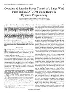
Fig. 1. Block diagram of line-shaft driven cam/follower compliant load system.
Fig. 2.
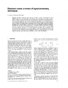
Block diagram of the electronic line-shafting control system with variable axis ratioing.
The physical line-shaft drive is modeled as a simple speedregulated drive. The physical connecting shaft model includes relative shaft stiffness and relative shaft damping terms. The output (transferred) torque is proportional to these terms and is applied to the follower drives as the driving torque and is reflected back to the line-shaft machine as load torque. These two paths are responsible of the inherent tie between the line-
shaft machine and the follower drives which will be emulated in the proposed topology. The cam model is split into two blocks: the forward motion kinematics block and the reflected force kinematics block. In the physical cams, the motion and force kinematic relationships depend on the cam surface profile. In this case, they consist of either a lookup table or a simple function. These relationships
ANDERSON et al.: WEB MACHINE COORDINATED MOTION CONTROL VIA ELECTRONIC LINE-SHAFTING
249
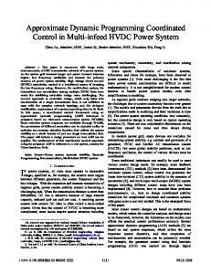
Fig. 3. Enhanced electronic line-shafting control system with infinite static stiffness and improved command tracking.
are identical to those used in classical kinematic system analysis and are based on the Jacobian matrix (a partial differential equation model description). III. ELECTRONIC LINE-SHAFTING CONTROL Fig. 2 shows the block diagram of the proposed control structure. This control structure exactly replicates the mechanical line-shaft cam/follower compliant shaft machine of Fig. 1. It contains, a “virtual line-shaft prime mover,” a “virtual, compliant but well damped, connecting shaft,” and a “virtual cam” to replace the physical elements. The physical line shaft drive is modeled as a well-damped virtual line-shaft drive. As in the physical case, the velocity command for the line-shaft drive establishes the operating speed level of the entire system. Since the virtual line-shaft drive is not and are relatively unconstrained physical, the values of design variables. The virtual compliant connecting shaft establishes the basic relative state feedback needed to force the line-shaft to slow down or to speed up according to the load changes. Unlike its physical counterparts, it can include significant damping without incurring any power dissipation. This virtual shaft provides the coordination needed for relative motion control. The virtual cam makes it possible to handle variable kinematics relationships that are often encountered in filament winding machines and web winding machines. By using virtual cams it is easy to map from the virtual line shaft reference signal states to the required trajectory of any of the connected
axes, whatever this trajectory could be. The virtual line shaft acts as a state filter to generate the needed position, velocity, and acceleration inputs via the forward motion kinematics of the virtual cam. The virtual line shaft also directly responds to the reflected force via the inverse kinematics of the virtual cam. This again exactly replicates the physical system. It is important to recognize that this “electronic line-shafting” control is an improvement over the physical system due to inherent ability to introduce nondissipative damping.
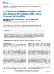
IV. ENHANCED “ELECTRONIC LINE-SHAFTING” CONTROL Fig. 3 shows the enhanced control block diagram. This topology includes some basic enhancements to the electronic line-shaft that do not have a physical counterpart. These enhancements include: 1) the addition of state integrators on the relative position error and 2) full state command feedforward. The state integrators have infinite dc gain. Thus, as part of the virtual connecting shaft control they produce a zero steady-state windup attribute, i.e., infinite static stiffness which cannot be achieved by physical shafts. The state command feedforward improves dynamic tracking during speed changes of the system. It is, of course, dependent on the feedforward parameter accuracy. Finally, Fig. 4 shows the electronic line-shafting control structure extended to multi-axis systems. Each axis provides its part of the disturbance torque to the virtual line shaft which, in turn, responds to keep the system synchronized.
250
IEEE TRANSACTIONS ON INDUSTRY APPLICATIONS, VOL. 37, NO. 1, JANUARY/FEBRUARY 2001
Fig. 4.
Block diagram of variable-ratio electronic line-shafting extended to multi-axis systems.
Fig. 5. Experimental five-axes filament winding web-machine layout.
V. EXPERIMENTAL FIVE-AXES FILAMENT WINDING WEB MACHINE The mechanical layout of the test system is presented in Fig. 5 and shows the independent axes which produce the synchronized motion of the web. This filament winding web machine is capable of cylindrical coordinate motions in space. Mandrel
and carriage are the two terms used to describe axes 1 and 2, respectively, that were used for this evaluation. In this configuration, axis 1 has a direct one-to-one mapping of the virtual line shaft states, and axis 2 follows a 1-m amplitude sinusoidal (variable kinematics) trajectory. The new motion control system was specified to be capable of generating and executing full six-axes synchronized motion. It was implemented utilizing an embedded PC board (EPC), an embedded 25-MHz 32-bit floating-point dual digital signal processor (DSP) board, analog and digital I/O boards, and an encoder interface board (Fig. 6). The control computer was configured around a VME-bus platform for reasons of high-performance and interface board availability. The two system components which perform all of the system’s required computational tasks are the EPC and the dual DSP board. The EPC board performs two vital functions. First, it is the VME system controller and, therefore, oversees and directs all of the VME bus communication. Secondly, it is a fully functional PC and is the operator’s interface, performs all of the system setup tasks, and displays current telemetry and state information. The DSP was selected to provide real-time computational resources for the system. It provides all of the machine sequencing for motion tasks, execute the motion control algorithms, generates command trajectories, and gathers the telemetry data from the axes and relays.
ANDERSON et al.: WEB MACHINE COORDINATED MOTION CONTROL VIA ELECTRONIC LINE-SHAFTING
251
Fig. 6. Two-axes configuration of the VME-based electronic line-shaft controller.
(a)
(a)
(b)
(b)
Fig. 7. Experimental results with axis 2 in force saturation: axes 1 and 2 responses using master–slave control. (a) Axis 1 response. (b) Axis 2 response.
Fig. 8. Experimental results with axis 2 in force saturation: axes 1 and 2 responses with electronic line-shaft control. (a) Axis 1 response. (b) Axis 2 response.
The timer which drives the real-time interrupt is triggered every 1 ms. When the interrupt occurs, the run time portion of the DSP code is executed. Its tasks include reading the encoder counters, computing the corresponding velocity estimator for each of the axes by using observer algorithms [8], and com-
puting relative stiffness control loops. Once the time critical real-time portion of the DSP code has been completed, the remaining time in the sample period is available for the background tasks. All of the tasks for the six-axes version of the motion control system easily fit in one of the DSPs.
252
IEEE TRANSACTIONS ON INDUSTRY APPLICATIONS, VOL. 37, NO. 1, JANUARY/FEBRUARY 2001
TABLE I EXPERIMENTAL RESULTS WTH PHYSICALLY BOUNDED (SATURATED) AXIS 2 TORQUE OUTPUT
(a)
(a)
(b)
(b)
Fig. 9. Experimental results with axis 2 in velocity saturation: axes 1 and 2 responses using master–slave control. (a) Axis 1 response. (b) Axis 2 response.
Fig. 10. Experimental results with axis 2 in velocity saturation: axes 1 and 2 responses with electronic line-shaft control. (a) Axis 1 response. (b) Axis 2 response.
VI. EXPERIMENTAL EVALUATION
the some of the better existing control topologies and the proposed control, tests were run for both master–slave control and electronic line-shafting control. During transient conditions, such as a sudden load disturbance, the enhanced behavior of the electronic line-shaft control
The main advantages of the proposed electronic line-shafting control topology show up during transient conditions and during drive saturation in any of the axes. In order to compare between
ANDERSON et al.: WEB MACHINE COORDINATED MOTION CONTROL VIA ELECTRONIC LINE-SHAFTING
253
TABLE II EXPERIMENTAL RESULTS WITH PHYSICALLY BOUNDED (SATURATED) AXIS 2 VELOCITY OUTPUT
comes from two facts. First, each axis drive is torque controlled and, therefore, responds faster than speed-controlled drives used in master–slave (and synchronous command) control. Secondly, at the same time, the increased load torque causes the disturbed axis velocity to slow down; this torque is also reflected back to the virtual line-shaft causing the virtual reference to slow down, which forces the other axes to also slow down. During slave drive current (torque) limited operation, the master–slave control is unable to maintain synchronization between the different axes due to the absence of inter-axes relative stiffness. Figs. 7 and 8 compare the results obtained under torque limits between the classical master–slave control and the proposed electronic line-shaft control. These figures stand in stark contrast. The master–slave control system develops significant following errors, and becomes virtually unstable due to the windup of axis 2’s state integrators. The electronic line-shaft control maintains a stable system response while reducing axis 2’s position and velocity following errors by a factor larger than ten (Table I). Furthermore, no windup appears between the axes. The other physical drive limit that affects performance of classical control methods is maximum velocity. To evaluate velocity limited operation, the velocity limit for axis 2 was set to about 0.5 m/s. The experimental results are presented in Figs. 9 and 10. The master–slave control is unable to maintain synchronized motion control between the two axes. In the electronic line-shaft control, the relative stiffness loop forces the trajectory of the virtual reference to nearly match the maximum axis 2 velocity and, through the virtual line-shaft, forces all of the axes to track the command at the highest feasible speed for the system. The results for the two control configurations are summarized in Table II. It can be seen that electronic line-shafting control has reduced the following error to almost one percent of the error in master–slave control. VII. CONCLUSIONS Synchronized motion control of web machines can be dramatically enhanced by proper control methods. The electronic line-shafting control method presented here has demonstrated a significant improvement in web process control over both classical synchronized command methods and fixed-ratio relative stiffness methods. The electronic line-shaft controller emulates the basic properties of systems that are mechanically linked. This virtual mechanism imparts excellent properties when the system is loaded or runs into torque or velocity limits.
The simplest form of electronic line-shaft control inherently can provide a form of nondissipative coupling/shaft damping which is extremely difficult to achieve by purely mechanical means. The enhanced form of electronic line-shafted control adds features that cannot be achieved in mechanically connected systems. For example, an infinite static stiffness connecting shaft may be produced (in addition to being well damped). This implies that no connecting shaft windup needs to be tolerated when the electronic line-shaft configuration is used. In addition, the enhanced electronic line-shaft also can use feedforward to assure tracking during speed changes, such as those that normally occur during startup and shutdown. This paper has also extended the basic relative stiffness control methodology for web machines to include variable kinematic relationships for both motion and forces. This control structure is especially helpful in maintaining synchronized motion control during web-process startup and shutdown sequences where ratios are dynamically changing. The main practical benefits of using the electronic line-shafting control, as compared to master–slave and synchronous command current controls, are as follows: 1) It allows an operation free of interruptions by properly handling transient disturbances and drive limits and, therefore, avoiding damage or cuts in the process web due to transient loss of synchronization. 2) It allows 100% utilization of the rated drive/motor capability. Current control topologies, in order to avoid drive operation in torque or velocity limits, rate drive/motor capacity with 20% torque and velocity margins above the maximum operating values. Although the implementation of the electronic line-shaft control is more hardware and software demanding than classical methods, its requirements should fit in system capabilities of current digital drives. In the six-axes control system developed in this paper, the real-time tasks consumed approximately 29% of the 1-ms sample period, and the amount of memory required to perform the given tasks was about one-half of the 48 32 K available program memory. REFERENCES [1] C. S. Lin, P.-R. Chang, and J. Y. S. Luh, “Formulation and optimization of cubic polynomial joint trajectories for industrial robots,” IEEE Trans. Automat. Contr., vol. AC-28, pp. 1066–1074, Dec. 1983. [2] S. Abe and T. Tsuchiya, “Robot manipulator path control based on variable speed trajectory planning,” Adv. Robot., vol. 6, no. 1, pp. 1–13, 1992.
254
IEEE TRANSACTIONS ON INDUSTRY APPLICATIONS, VOL. 37, NO. 1, JANUARY/FEBRUARY 2001
[3] M. Koga, K. Kosuge, K. Furuta, and K. Nosaki, “Coordinated motion control of robot arms based on the virtual internal model,” IEEE Trans. Robot. Automat., vol. 8, pp. 77–85, Feb. 1992. [4] J. Dinsdale, P. Jones, and M. Thornecroft, “The electronic gearbox—Computer software replaces mechanical couplings,” in Ann. CIRP, vol. 31, 1982, pp. 247–249. [5] R. D. Lorenz and P. B. Schmidt, “Synchronized motion for process automation,” in Conf. Rec. IEEE-IAS Annu. Meeting, 1989, pp. 1693–1699. [6] R. G. Anderson, “Coordinated motion control of multi-axis machines via electronic line shafting,” M.S. thesis, Dep. Mech. Eng., Univ. Wisconsin, Madison, Sept. 1994. [7] A. J. Meyers, “Design and implementation of a multiprocessor control system for a multi-axis, cross coupled machine control,” M.S. thesis, Dept. Elect. Comput. Eng., Univ. Wisconsin, Madison, Dec. 1994. [8] R. D. Lorenz and K. Van Patten, “High resolution velocity estimation for all digital, AC servo drives,” IEEE Trans. Ind. Applicat., vol. 27, pp. 701–705, July/Aug. 1991. [9] R. G. Anderson, R. D. Lorenz, and A. J. Meyer, “Method for coordinating motion control of a multiple axis machine,” U.S. Patent 5 659 480, Aug. 1997.
Robb G. Anderson received the B.M.E. degree from the University of Minnesota, Minneapolis, and the M.S. degree in mechanical engineering from the University of Wisconsin, Madison, in 1992 and 1994, respectively. While at the University of Wisconsin, he performed research in the area of machine control. This work included specific research in the area of filament winding machines, sponsored by McClean Anderson, Wausau, WI. The research produced a novel control technique termed “electronic line-shafting,” which formed the basis for his thesis and a corresponding patent, held by McClean Anderson. In 1994, he joined McClean Anderson as a Senior Mechanical and Control Engineer. His duties include machine design, offline software development, and design and support of PC/DSP-based filament winding machine control systems.
Andrew J. Meyer received the B.S. degree in systems engineering from Boston University, Boston, MA, and the M.S. degree in electrical engineering from the University of Wisconsin, Madison, in 1992 and 1994. While at the University of Wisconsin, he worked on the implementation of electronic line-shafting techniques in industrial machine control. The research was sponsored by McClean Anderson, Wausau, WI, a world-wide supplier of industrial filament winding equipment. In 1994, he joined McClean Anderson as an Engineer. His primary responsibility was to create a market-ready next-generation motion control system for the control of industrial filament winding equipment utilizing electronic line-shafting technology. This work resulted in the release of McClean Anderson’s Omniwind machine control system in 1996. He is currently a Senior Engineer at the Genomics Institute of the Novartis Research Foundation (GNF), San Diego, CA. GNF is conducting research in a wide range of related areas, including functional genomics, molecular and structural biology, bioinformatics, combinatorial chemistry, and proteomics. He is responsible for controls, software, and instrumentation involved in the development of automated solutions for high-throughput chemical and biological synthesis and discovery.
M. Anibal Valenzuela received the Electrical Engineering degree and the Magister degree in electrical engineering from the University of Chile, Santiago, Chile, in 1976 and 1978, respectively. Since 1978, has been with the Department of Electrical Engineering, University of Concepción, Concepción, Chile, where he is an Associate Professor in the area of electric machines and drives. His research interest is focused on motion control of industrial drives and coordinated motion of multi-axes systems.
Robert D. Lorenz (M’84–SM’91–F’98) received the B.S., M.S., and Ph.D. degrees from the University of Wisconsin, Madison, in 1969, 1970, and 1984 respectively. Since 1984, he has been a member of the faculty of the University of Wisconsin, Madison, where he is the Consolidated Papers Foundation Professor of Controls Engineering in both the Mechanical Engineering and Electrical and Computer Engineering Departments. In this position, he acts as Co-Director of the Wisconsin Electric Machines and Power Electronics Consortium. He is also an active consultant to many organizations. He was a Visiting Research Professor in the Electrical Drives Group, Catholic University of Leuven, Leuven, Belgium, in the summer of 1989 and in the Power Electronics and Electrical Drives Institute, Technical University of Aachen, Aachen, Germany, in the summers of 1987, 1991, 1995, 1997, and 1999. In 1969–1970, he conducted his M.S. thesis research at the Technical University of Aachen. From 1972 to 1982, he was a member of the research staff at the Gleason Works, Rochester, NY. His current research interests include sensorless electromagnetic motor/actuator technologies, real-time signal processing and estimation techniques, precision multi-axis motion control, and ac drive and high-precision machine control technologies. Dr. Lorenz is currently the IEEE Industry Applications Society (IAS) President, a Distinguished Lecturer of the IAS for 2000/2001, the immediate Past Chair of the IAS Awards Department, and past Chairman of the IAS Industrial Drives Committee. He is a member of the IAS Industrial Drives, Electrical Machines, Industrial Power Converter, and the Industrial Automation and Control Committees. He is a member of the IEEE Sensor Council AdCom and the IEEE Neural Network AdCom. He is a Registered Professional Engineer in the States of New York and Wisconsin. He is also a member of the American Society of Mechanical Engineers, Instrument Society of America, and Society of Photo-Optical Instrumentation Engineers.