Integration formulas sin (. ) y D A. B x C. = +. â. A is amplitude B is the affect on the period (stretch or shrink).
WATER SIDE HVAC FORMULAS. BTUH = GPM x 500 x T (water). TONS = GPM
x ΔT. 24. (CH water) (CT Ton = 15,000 BTUH). FTHD = psi x 2.31. S.G.. NPSHA.
Oct 29, 2014 - Abstract. In this paper we give a combinatorial proof of an addition formula for weighted partial Motzkin paths. The addition formula allows us to ...
Description: Excel has hundreds of functions and nobody knows them all, but
spend some ... Handouts available in Adobe Portable Document Format (PDF)
for.
... constants, and even functions. Here is an example Excel formula that we have
labeled for your understanding. Advertise on Tizag.com. =B3 * 5 / SUM(B4:B7).
+358 9 8949 2227. FI-00421 Helsinki. Finland. Visit our Internet ..... 49.63 g/kg. (To obtain the mixing ratio in units of grains/pound use B = 4 354 [grains/pound]) ...
Advanced Calculus Formulas a = 〈a1, a2, a3〉 b = 〈b1, b2, b3〉 c = 〈c1, c2, c3〉 r =
〈x, y, z〉 r0 = 〈x0, y0, z0〉 n = 〈n1, n2, n3〉. Dot (Scalar) Product: a · b = a1 b1 + ...
PHYSICS FORMULAS. 2426. Electron = -1.602 19 × 10-19 C. = 9.11 × 10⁻³¹ kg.
Proton. = 1.602 19 × 10-19 C. = 1.67 × 10⁻²⁷ kg. Neutron. = 0 C. = 1.67 × 10⁻²⁷ ...
PHYSICS FORMULAS. 2426 .... 360° to obtain the value closest to the reference
angle. To convert from ... Electric Field due to an infinite sheet: [N/C]. E = ∈ σ.
Horsepower. HP= PRESSURE (PSI) X FLOW (GPM). = P xQ. 1714. FLUID
POWER IN HORSEPOWER. 1714 .3208 x FLOW (GPM). INTERNAL AREA (Sq In
).
The metric of Space-Time . ..... A second version was made (in Microsoft W ord and html) around 1996, which included now a discussion of flat models with ...
The two points are (2,3) and (3,2) , so the distance is. 2. 2. (2 3) (3 2). 2. â. + â .... at the lattice point (0,1
TRIGONOMETRY. Right Triangle Definitions. Circular Definitions. Other Identities
sin cos tan sec csc opp adj hyp hyp opp adj cot adj opp hyp hyp adj opp θ θ θ.
Page 1 ... For the list on the left, name the compound. For the list on the right, give
the chemical formula that corresponds to the name. Name. Formula. 1). NaF.
The Most Important Functions and Formulas for Finance (IB, PE,. HF/AM, ER, CF,
etc.) ... Removes all non-printable characters from text. =UPPER(Text).
Quantum Mechanics Formulas. Constants. ¯h ≡ h. 2π. De Broglie–Einstein
Relations. E = ¯hω p = ¯hk. Dispersion Relations ωlight(k) = ck ωelectron(k) = ¯
hk2.
How is it possible for us to have free will, for example, supposing that ... called "the view from nowhere" â a completely neutral account of objective reality -- requires ... (Aronowitz and Giroux 1993), Peter McLaren (1994), Michael Apple (1990,
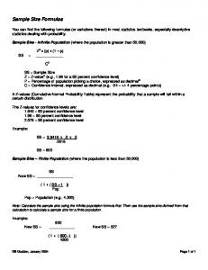
You can find the following formulae (or variations thereof) in most statistics
textbooks, especially descriptive statistics dealing with probability. Sample Size ...
(a) A retaining wall maintains unequal levels of earth on its two faces. The most
com- mon types ... cases of design should be investigated for a basement wall.
First. when the wall .... Adjustment of woli Dose, example 14.3. . Assuming 0.0!
steel
Page 1 of 1. Formulas geometricas.pdf. Formulas geometricas.pdf. Open. Extract. Open with. Sign In. Main menu. Displayin
In these circumstances breast milk has some limitations. For example, in pre- term infants with a birth weight less than
Ingredients like Brussels sprouts, kale, and grape-seed extract aren't typically seen on feed labels. Whole food ingredi
BEAM DEFLECTION FORMULAS. BEAM TYPE. SLOPE AT ENDS. DEFLECTION AT ANY SECTION IN TERMS OF x. MAXIMUM AND CENTER. DEFLECTION.
Excel Sioiisiicol. Functions. Descriptive Statistics 200? Function 2010 Function.
Number of data items C OUNT(Data} COUNTfiData). Largest data value ...
ELECTRONIC FORMULAS. Ohm's Law Formulas for D-C Circuits. Ohm's Law
Formulas for A-C Circuits and Power Factor. In the above formulas 1 is the angle
...
ELECTRONIC FORMULAS Ohm's Law Formulas for D-C Circuits.
P ' PR I
E ' IR '
P ' I 2R ' EI '
E2 R
Ohm's Law Formulas for A-C Circuits and Power Factor.
P ' E ' IZ ' I cos1
PZ cos1
P ' I 2 Z cos1 ' IE cos1 '
E 2 cos1 Z
In the above formulas 1 is the angle of lead or lag between current and voltage and cos 1 = P/EI = power factor or pf. Active power (in watts) P R pf ' ' pf ' Apparent power (in volt&s) EI Z Note: Active power is the "resistive" power and equals the equivalent heating effect on water.
Voltage/Current Phase Rule of Thumb Remember "ELI the ICE man" ELI: ICE:
Voltage (E) comes before (leads) current (I) in an inductor (L) Current (I) comes before (leads) Voltage (E) in a capacitor (C)
Resistors in Series
Rtotal ' R1 % R2 ' R3 % ...
Two Resistors in Parallel
Rt '
R1 R2
Resistors in Parallel, General Formula
R1 % R2
1
Rtotal '
1 1 1 % % %... R1 R2 R3
Resonant Frequency Formulas *Where in the second formula f is in kHz and L and C are in microunits. f '
1
,
or
f '
2B LC
Conductance
159.2(
L '
LC
G '
Reactance Formulas
Impedance Formulas
Q or Figure of Merit
1 R
1 , 4B2f 2C
G '
(for D&C circuit)
XC '
1 2Bf C
C '
Z ' R 2%(XL&XC)2
Q '
XL R
or
or
L '
25,330( f 2C
R R %X 2 2
1 2Bf XC
(for series circuit)
XC R
2-7.1
C '
1 , 4B2f 2L
or
C '
25,330( f 2L
(for A&C circuit)
XL ' 2BfL
Z '
L '
RX 2
R %X
XL 2Bf
(for R and X in parallel) 2
Frequency Response "Cartoon" memory aid
Inductor * Capacitor * Resister
DC
Pass
Block
DC Blocked
Attenuate DC Passes
Low Freq Attenuate * Attenuate * AC High Freq
Block
Pass
Attenuate High Freq Passes
Attenuate
High Freq Blocked
* Attenuation varies as a function of the value of the each device and the frequency
Sinusoidal Voltages and Currents
Peak Effective Average
Effective value = 0.707 x peak value [Also known as Root-Mean Square (RMS) value]
TIME
Half Cycle Average value = 0.637 x peak value Peak value
= 1.414 x effective value
ˆ Effective value
= 1.11 x average value
Three-phase AC Configurations (120E phase difference between each voltage) If the connection to a three phase AC configuration is miswired, switching any two of the phases will put it back in the proper sequence. Electric power for ships commonly uses the delta configuration, while commercial electronic and aircraft applications commonly use the wye configuration. Color Code for House Wiring: Black or red White Green or bare
PURPOSE: HOT NEUTRAL (Return) GROUND
Color Code for Resistors: First and second band: (and third band # of zeros if not gold/silver) 0 Black 5 Green 1 Brown 6 Blue 2 Red 7 Violet 3 Orange 8 Gray 4 Yellow 9 White
Delta
Wye (Y) or Star
Color Code for Chassis Wiring: Red White Black Third band Multiplier .1 Gold .01 Silver
Fourth band Tolerance 5% Gold 10% Silver 20% No color
The third color band indicates number of zeros to be added after figures given by first two color bands. But if third color band is gold, multiply by 0.1 and if silver multiply by 0.01. Do not confuse with fourth color-band that indicates tolerance. Thus, a resistor marked blue-red-gold-gold has a resistance of 6.2 ohms and a 5% tolerance.