ROBERT NEFF, SCOTT SCHWARTZ, and DAVIn G. STORK. Swarthmore College, Swarthmore, Pennsylvania. We present a design for a versatile electronic ...
Behavior Research Methods, Instruments, & Computers 1985, 17 (3), 363-370
METHODS & DESIGNS
Electronics for generating simultaneous random-dot cyclopean and monocular stimuli ROBERT NEFF, SCOTT SCHWARTZ, and DAVIn G. STORK Swarthmore College, Swarthmore, Pennsylvania
We present a design for a versatile electronic device that produces simultaneous dynamic cyclopean (disparity) and monocular visual stimuli on standard monitors. These stimuli consist of dynamic random-dot cinematograms with the cyclopean and monocular components under realtime simultaneous but independent control. For example, one possible stimulus consists of a horizontal sinusoidal disparity grating moving upward in the frontal plane, made from randomdot fields that move to the right at an arbitrary speed. The device can be controlled by any microcomputer with serial input/output capability. Static random-dot stereograms have been used extensively in research of cyclopean brain functions (see, e.g., Julesz, 1971). Dynamic random-dot cinernatograms must be used to investigate the cyclopean response to motion, such as the cyclopean motion aftereffect (Papert, 1964). Early cinematograms were produced as movies, precluding easy real-time interactive control (Julesz). Later efforts (Shetty, Brodersen, & Fox, 1979) enabled realtime dynamic control of only coarse cyclopean stimulus features. In these and other investigations, the monocular stimulus fields from which the cyclopean stimuli arose were temporally random, or "snowy." All coherent motion, then, was at the cyclopean level; there was no coherent motion at the monocular level. If the subject closed one eye, all coherent motion and relative depth disappeared. To investigate the interaction between motion responses at the monocular and the cyclopean stages of the visual system, we devised a novel stimulus. The stimulus consists of a spatially periodic disparity-grating of arbitrary depth contour, that can move at arbitrary speed and nearly arbitrary direction. For instance, it can have a sine wave, square wave, or an arbitrary depth contour, and it can move at arbitrary speed (including zero) in either direction perpendicular to its wavefront. For any of these disparity conditions, the monocular records can be independently controlled: For instance, the individual dots comprising the right eye's and the left eye's images (the right and left records) could be temporally uncorrelated snow, This work was supported by Grant EY -05342 from the National Institute of Health. National Eye Institute. to Dr. Stork. Reprint requests should be addressed to: David G. Stork. Physics Department and Neuroscience Program. Clark University. 950 Main Street. Worcester. MA
01610.
could be random and approximately static, or could flow coherently in an arbitrary direction and speed. This last feature permits us to produce stimuli in which the direction of motion of the disparity stimulus-the cyclopean motion-is different from the direction of the monocular motion. To envision the appearance of one such stimulus (here, an upward moving disparity grating with rightward moving monocular dots), a person can imagine viewing the following: a large, randomly spotted carpet lying atop parallel, horizontal cylinders on a floor. If the rollers move upward along the floor, the viewer sees a horizontal disparity grating moving upward in the vertical plane. If at the same time the carpet is pulled to the right, there will be monocular motion to the right. Presumably, as subjects view such a stimulus, their motion-sensitive systems that are stimulated monocularly process rightward motion, while their motion-sensitive systems that are stimulated by binocular disparity stimuli process upward motion.
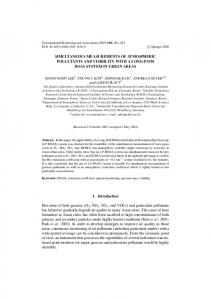
Theory and overview of electronics The electronics have been designed as' several distinct parts which connect simply. These parts include a computer interface, pseudo-random bit generator, pixel density control, monocular motion generator, cyclopean motion controller, video timing circuit, and video output circuit (Figure I). In broad outline, the components produce the stimuli as follows: The pseudo-random bit generator (PRBG) and the pixel density control (PDC) make a pseudo-random bit stream of arbitrary density (i.e., ratio of high- to lowvoltage periods). These bits eventually appear as dots on the display monitors. The monocular motion generator (MMG) controls this data stream to form a static, moving,
363
Copyright 1985 Psychonomic Society, Inc.
364
NEFF, SCHWARTZ, AND STORK nonac. motton
""6
Vtd_o
sync
Pixel
densny control poe
"v
" 't
ss . s
Com ute'"
"ED0
u Right
Cyclopeen (d1spertty)
Video
control
CC
Figure 1. Functional block diagram. The computer interface sends controlling signals to the MMC, PDC, and CC. The clock and the video synchronization sections generate all necessary timing pulses.
or temporally random video image by resetting the PRBG at appropriate points in the display cycle. The cyclopean controller (CC) takes this bit stream and separates it into two streams, one for the left record, the other for the right record. It also introduces a relative shift between these two bit streams, which is translated into a relative spatial shift between the images of the right and the left records on the display screens. When viewed stereoscopically, via Wheatstone mirror system or red-green anaglyph system, as desired, this relative shift is interpreted by the subject as depth. The information from the CC is processed by the video output circuit and appears on the two video monitors. Meanwhile the video timing circuit generates necessary synchronizing signals used throughout the system. Timing signals are based on a 19.66 MHz crystal oscillator, which is divided to produce the frequencies needed in circuit. The oscillator is used at its full rate in the CC. The timing signal is divided to produce a 9.83 MHz signal used as a pixel rate clock in the PRBG and the MMG. Further clock divisions are required for video timing and serial input/output (I/O).
Pseudo-Random Bit Generator (PRBG) and Pixel Density Control (PDC) The source of the pseudo-random dot pattern is the PRBG, which provides feedback by means of a series of shift registers and XOR gates. Our circuit utilizes the PRBG described by Horowitz and Hill (1983, p. 437). It consists of a series of shift registers (74LSl64) and a few XOR gates (74LS86) (Figure 2). The output is a pseudo-random bit sequence, with a repeat cycle of 22 4 bits when run without reset. When reset, the PRBG begins to generate the same pseudo-random pattern every time. In experiments, we have found that this pattern is suitably random and the resulting dot pattern is not recog-
nized as the same from trial to trial. However, should a different random pattern be desired, it can be produced by using different feedback connections to the XOR logic. Each shift register has eight outputs from which data are available. Anyone of these outputs will have a bit density of 50% (i.e., half of the bit periods are assigned a high voltage, the other half a low voltage); by ANDing together several of the outputs, the net pixel density (the proportion of high voltage periods) may be decreased by a factor of 2, 4, 8, and so forth. Conversely, the bit density may be increased by ORing the outputs from the shift registers. The PDC, diagrammed in Figure 3, performs the ANDing described above.
Monocular Motion Controller (MMC) A static, monocular pattern is produced by resetting the PRBG at the same point on each screen; under such conditions, the same image is presented to a display monitor on each frame. This proper resetting is achieved in hardware by counting pixels and resetting the PRBG after a complete screen of pixels has been counted. Coherent monocular motion of each record is achieved by slightly varying this reset count; a higher count means adding bits to the data stream, a lower count means removing bits from it. For rightward motion of each record, the bit counter (the network of74LS161s in Figure 4) is programmed to count for one full screen plus one pixel before resetting. Rightward monocular motion occurs as each pixel on the display monitor moves to the right by one pixel width each time the screen is refreshed. Downward vertical monocuR(SET
PIXU ClOCk
• •
I
23 51
...
•
~ 0
6
~
-.;.'" ,... ""
10
} .. .
poe
13
1 2 51
... ...-co
",co. ...J-
,...... '"
I
2
5'
'21--------' 131------------'
Figure 2. Pseudo-random bit generator (PRBG). This PRBG has a free running repeat cycle of 224 bits, and includes a reset function, controlled by the MMC.
SIMULTANEOUS CYCLOPEAN AND MONOCULAR STIMULI
...
74LSOO """""""",, D-' )()-
From
PNBlJ
"JO--'
)::
'"' ' ' ' ' ' ::.:;.,:]L
1\ .
0
'"'"... P-
....
7lJ
'-
74lS00
I
I
01
7'1LS377
f
II
I
I
I
I
I
DO
Figure 3. The pixel density control (PDC). This circuit selects the density of pixels, based on the number of high bits stored in the 74LS377. The pixel density equals 2 - n, where n is the number of high bits set. The 74LS377 is loaded with a pattern of Is and Os, and where there is a 1 the corresponding input from the PRBG is ANDed with other inputs to generate the output data stream. When the 74LS377 is loaded with 11111111 (base 2) the output data stream is least dense, with 1 pixel for every 255 blank spaces. If the 74LS377 is loaded with 00000oo1 (base 2) the output data has a pixel density of 50%.
lar motion is achieved in an analogous manner; the bit counter is programmed to count for one full screen plus one line before resetting, thus adding one complete line per screen refresh. Motion in the opposite direction is achieved by removing lines or bits rather than adding them. Diagonal motion, a combination of the horizontal and vertical effects, is accomplished by adding or removing a nonintegral number of lines. [The process of creating the appearance ofdiagonal motion can be thought of as vector addition of the horizontal and vertical effects; the horizontal component involves units of one bit, and the vertical component involves units of 512 bits (in our case). The velocity resolution corresponds to one bit per frame.'] To increase the velocity, more pixels or lines are added per refresh by making the reset count adjustment larger. For example, adding two pixels per screen refresh gives rightward motion twice as fast as adding only one pixel. Specifically, this resetting is achieved in the following way: The 74LS161 counters, which are loaded by the computer with a number, count from this number up to an overflow, and then are loaded again, simultaneously resetting the PRBG. To count for one entire screen, the counters must be loaded with a number equal to their total count (21 4 ) minus the total number of pixels per screen refresh. This number is loaded into the three 8-bit registers (74LS377) shown in Figure 4. Temporally random patterns are displayed by disabling the reset function and letting the PRBG free run. The control for disabling the reset function is the most significant bit of the first control register (the top bit in Figure 4). When this bit is set low, the resetting function is disabled and snowy patterns are displayed on the screen. For a static display, this bit must be set high to enable the resetting operation.
365
By sending a sequence of speed and direction instructions to the apparatus via a computer link, the experimenter may control a dynamically changing monocular background in real time. Unfortunately monocular speed resolution is low, since the counters must add an integral number of pixels or lines to the screen per refresh. In practice we have been able to use four speeds in any direction with this circuit. Cyclopean Waveform Generation The cyclopean depth effect is attained by displacing each pixel in one field of view (the left record, for instance) an amount left or right relative to the corresponding dot in the other field of view (the right record) (Julesz, 1971). In producing horizontal disparity gratings, a disparity of N pixels for a given display line is achieved by shifting the bit stream for the left record by N/2 pixel periods, and the bitstream for the right record by - N/2 pixel periods. To do this, the output from the PRBG and PDC is fed into two serial-in/parallel-out shift registers (74LSI64), 16 bits in total length. Two 74150s, connected to the parallel outputs of the shift-register, are used as l-of-16 data selectors. One 74150 sends data to the left record; the other sends data to the right record. These components create a spatial shift on the video monitor by
,
D1
4 7
D
8 13 14
DO
.
...'"'"
....
~17>~
12
6
lS~S
74lSt61
17
'6~4
18
19
,
2
f------ :5 6
5-S
7
,-4
.... ....
.
..."" " ....'" 14
74LSl61
,
10
12
6
1S
15- 5
74lS161
16-4
>- 18
19_3
S
I---
S
r--
4
I - 14 I- " ~
IB
.
'" ...'"
s--
10
74lS161
, -,
10
6
IS
"
I~
t--'!-- I---< 2
~ 2
-
1S
6
1-"
pixel Clock
6
4
.... ....
2
I
2
1
,
-"----
I
,
-17
,
10
15
4
,
-
.... ....
.z, 2
15~5
74lS161
16-" '9~3
f--'!..-f-2
Figure 4. The monocular motion controller (MMC). The three 74LS377s hold a number sent from the computer interface. This number is loaded into the 74LS161 binary counters, which are clocked by the system clock. When the 74LS161s overflow, "Reset" is momentarily drawn low, the number is reloaded, and the PUG is reset (not shown). If the top bit in the top 74LS377 is set low, the reset function is disabled.
366
NEFF, SCHWARTZ, AND STORK
delaying the output of information to one record with respect to the other. For instance, if the left record is reading bit 3 of the shift register and the right record is reading bit 12, the information displayed on the left record is delayed by 9 clock cycles before it is displayed on the right. Since a video monitor scans from left to right, this 6-cycle delay results in a disparity of 9 to the right on the right record with respect to the left record. In this circuit the disparities may range from 0-30, with o corresponding to the least apparent depth, and 30 corresponding to the greatest; a pixel with disparity value of 0 would appear to be close to the observer, while one with a value of 30 would appear far away. The shift registers are clocked at twice the pixel rate (i.e., at 19.66 MHz), allowing a minimum disparity of a half pixel width. This small disparity increment leads to stereo images that appear quite smooth and continuous. (The minimum angular disparity depends upon the monitors and optics employed, but probably is greater than the limit of stereoacuity.)
Cyclopean Controller (CC) To generate a horizontal cyclopean grating, a random access memory (RAM) is programmed before stimulus presentation with a set of 5-bit numbers, with each number indicating the value of the disparity on a given line of the record. During presentation, the RAM is read sequentially, with each successive entry controlling the disparity for a display line. After each line is displayed, the address of RAM is incremented by a line counter, and the disparity for the next line is used. For a stationary record, the line counter is loaded with a constant at the beginning of each refresh, giving the same count and the same data on the same lines on every refresh. In such a case, the horizontal grating does not move. This use of a programmable RAM allows enormous flexibility: The wave may be any function, including sine, square, and triangle waves, with any total depth or spatial frequency. The only restriction is that the RAM should be programmed with an integral number of waves; otherwise discontinuity problems may develop when the address increments from 255-0. Finally, the cyclopean gratings are limited to horizontal orientation. Consequently, cyclopean motion is vertical. To make the cyclopean pattern move requires another counter. This counter (the two 74LS19ls on the left in Figure 5) contains the number to be loaded into the line counter at the top of each screen. If it is not incremented, the line counter loads the same number on consecutive screens, and there is no cyclopean motion. If, however, the motion counter is incremented (decremented), the line counter starts at a higher (lower) number, shifting all the disparities up (down) on the record; thus, the cyclopean grating moves. (The cyclopean disparities move, but there is no effect on the motion of the monocular pattern. The two effects are completely independent.) In our circuit, there are two ways of controlling the cyclopean motion, by direction control and by speed con-
trol. Direction control is possible by using the up/down (U/D) input on the two 74LS19ls used as motion counters (Figure 5). When the input voltage is high (low), motion is up (down). For speed control, a digital frequency divider circuit is used. Typical speed of motion corresponds to approximately one line per frame. Controlling the speed requires incrementing the motion counter with the vertical synchronizing pulse (Vsync ) . To permit control in either direction, we start with a signal clocking at four times the V sync rate, and put it through a programmable divide-by-16 circuit consisting of a 74LS161 and an inverter. This circuit may divide by between 2 and 16, yielding the necessary control. Note that the fastest velocity is two pixels per frame, while the slowest is one pixel per four frames. An input of 1,111 base 2 results in no clocking, and no motion. Greater speed resolution is possible, using instead a divide-by-256 circuit (Lancaster, 1974, p. 244).
Computer Interface (CI) The computer interface (CI) shown in Figure 6 consists of two primary sections: The first converts a serial (RS-232) data stream into 16 bits of data and control information, and the second is a data distribution and control network that handles the flow of information across these lines to the control registers. The net result is that a command consisting of a few bytes of serial data may completely control the display. Because serial interfaces are common on microcomputers, the circuit can be controlled by practically any commercially available microcomputer. The transmission from the serial I/O line to the four internal ports requires that the data sent consist of 4 bits of data and 4 bits indicating to which port the transmission is addressed. The data are carried in the four least significant bits of the byte, and the four most significant bits correspond to data being sent to bits DO-D3, 04-07, AO-A3, and A4-A7 in Figure 6. Information lines DOto D7 are data lines which carry information to data registers in the apparatus. Lines AO-A7 carry address and control information, indicating which data register should accept the information or control a function. The circuit described has one idiosyncracy: It cannot write to the same internal port on consecutive bytes. (This problem occurs only when writing to the same port consecutively, and does not affect consecutive writes to different internal ports.) To write to 1001 to AO-A3, followed by 0100, one sends the following: Binary 0100 1001 0000 0000 0100 0100
Decimal 73
o
68
Comment Sends 1001 to AO-A3 Does nothing Sends 0100 to AO-A3
The baud rate clock for the AY3-1015 UART must be 16 times the baud rate desired for the rest of the device. We operated at 19,200 baud and required a clock of 307.2 kHz. This clock rate was generated by dividing the pixel
14
3
5
2
V sync
13
4
r--- t -
*
4
IS
r