Feb 27, 2018 - topology. Elmo encodes multicast group information inside ...... [32] Network World, âMulticast Group Capacity: Extreme Comes Out on. Top.
Elmo: Source-Routed Multicast for Cloud Services Muhammad Shahbaz
Lalith Suresh VMware
Princeton University
Jen Rexford
Ori Rottenstreich
Mukesh Hira
Princeton University
Princeton University
Technion
arXiv:1802.09815v1 [cs.NI] 27 Feb 2018
VMware
of publish-subscribe topics per tenant [17]. Infrastructure applications [18] running on top of provider’s network also need to replicate broadcast, unknown unicast, and multicast traffic for its tenants [19]. These types of workloads naturally suggest the use of multicast, yet today’s data centers typically do not deploy native IP multicast [20–22]. In practice, native IP multicast is not effective, since data-center tenants introduce dynamism into multicast groups, and routers and switches often cannot reconfigure IP multicast groups at the required rates [23, 24]. Specifically, IGMP [25] and PIM [26–28] trigger many control messages during churn, querying the entire PIM broadcast domain periodically; and are not robust to network failures [23, 24, 29, 30]. While SDN-based solutions alleviate the control plane shortcomings of IGMP and PIM, they still do not scale to support a large number of groups in a data center. In particular, switching hardware supports a limited number of groups only, typically thousands to a few tens of thousands [24, 31–33]. We believe that if cloud providers want to offer native multicast as a service to customers, they need to scale up to millions of multicast groups in a single data center. Instead, cloud providers and tenants typically implement multicast using a unicast overlay [34–40], which imposes significant CPU load and, thus, faces severe scalability limitations. Due to such scaling limitations, certain classes of workloads (e.g., many workloads introduced by financial applications [41]) cannot use today’s cloud-based infrastructure at all. In this work, we present Elmo, a system that scales to support millions of multicast groups in data centers. Our approach to scaling multicast groups is to encode the multicast tree in the packet header, as opposed to maintaining flow-table entries per group inside network switches. Such a solution can be more flexible and dynamic: because the group membership is encoded in the packet itself, groups can be reconfigured by merely changing the information in the header of each packet. The challenge in doing so involves finding the right balance between how much of the forwarding information to place in the packet header (inflating both the packet size and the complexity of parsing the packet header at each switch) and how much state to put in each switch (increasing memory requirements at the switch and
ABSTRACT Modern data-center applications frequently exhibit one-tomany communication patterns and, at the same time, require the fabric to provide sub-millisecond latencies and high throughput. Native IP multicast can achieve these requirements. However, native IP multicast solutions have scalability limitations that make it challenging to offer it as a service for hundreds of thousands of tenants, typical of cloud environments. Tenants must, thus, either add custom support for multicast in their applications or rely on services like overlay multicast, both of which are unicast-based approaches that impose their own overhead on throughput and CPU utilization, leading to higher and unpredictable latencies. In this paper, we present Elmo, a mechanism for native multicast in switches which takes advantage of the unique characteristics of data-center topologies and workloads. Specifically, the symmetric topology and short paths in a data center and the tendency of virtual machines (VMs) from individual tenants to cluster in small portions of the topology. Elmo encodes multicast group information inside packets themselves, significantly reducing the need to store multicast group information in individual network switches. In a data-center topology with 27K hosts, Elmo supports a million multicast groups using a 325-byte packet header while requiring as few as 1.1K multicast flow-table entries on average in leaf switches with a traffic overhead as low as 5%.
1
Nick Feamster
INTRODUCTION
Data-center applications are commonly driven by systems that deliver large amounts of data to groups of endpoints. Cloud providers, in turn, need to support hundreds of thousands of tenants, each of which may run tens to hundreds of such applications. Common workloads include streaming telemetry workloads [1–4], where hosts continuously send telemetry data in incremental updates to a set of collectors; replication for databases [5] and state-machines [6– 8]; distributed programming frameworks [9, 10]; as well as schedulers and load balancers that require a steady-stream of telemetry information about the load on servers to make effective server selection decisions [11, 12]. Publish-subscribe systems are also common building blocks for large-scale systems today [13–16]. These systems create a large number 1
limiting the rates at which multicast group memberships change). As long as group sizes remain small enough to encode the entire multicast tree in the packet, there is virtually no limit on the number groups Elmo can support. Previous native multicast designs explore the tradeoff between packet header size and switch memory in the context of arbitrarily flexible switch architectures [42–44]. This paper, on the other hand, studies this tradeoff in the context of data centers, where we can exploit the characteristics of data-center topologies to design a more efficient packetheader encoding that can be implemented and deployed on programmable switches today. This new context allows us to take advantage of the unique characteristics of data-center topologies. First, data-center topologies tend to be symmetric. Second, they have a limited number of switches on any individual path. Finally, to minimize internal bandwidth use in the data center itself, tenant allocation is such that many tenant virtual machines (VMs) tend to cluster in the same part of the data-center topology (in other words, for any given tenant, the VMs allocated to that tenant may create regions of the topologies that are significantly more dense than others) [45, 46]. The main result of this work is a mechanism, Elmo, to encode multicast forwarding rules in packets which takes advantage of these unique characteristics of multitenant data centers and to create an encoding for multicast groups that is compact enough to fit in a header that can be parsed by programmable switches that are being deployed in today’s data centers [47–49]. This paper makes the following contributions. First, we develop a technique for compactly encoding multicast groups that are subtrees of multi-rooted Clos topologies, the prevailing topology for today’s data centers [50–52]. To do so, we identify that today’s data-center topologies and placement of VMs create an opportunity to design a multicast group encoding that is compact enough for today’s data-center switches to process (§3). Second, we optimize the encoding so that it can be implemented in both hardware and software targets (§4). Our evaluation shows that this encoding facilitates a feasible implementation in today’s data centers (§5). In a data center with 27K hosts, Elmo scales to millions of multicast groups with minimal flow-table entries and control plane update overhead on switches. Our solution is also inexpensive to implement in programmable hardware and software switches. Lastly, it supports unmodified applications, of which we demonstrate two.
2
Control Plane
API
Controller
Data center Network
Data Plane
Multicast Tree
Host Hypervisor Switch
VMs & Containers
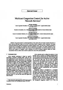
Figure 1: Elmo architecture. forwarding decisions for groups too large to encode entirely in the packet header). Performing control-plane operations at the controller and having the hypervisor switches place forwarding rules in packet headers, significantly reduces the burden on network switches for handling a large number of multicast groups. Figure 1 summarizes our architecture. Controller. The controller receives join and leave requests for multicast groups via an application programming interface (API). Cloud providers already expose these kinds of APIs [53] for tenants to request VMs, load balancers, firewalls, and other services. Each multicast group consists of a set of tenant VMs. The controller knows the physical location of each tenant VM, as well as the current network topology—including the capabilities and capacities of the switches, along with unique identifiers for addressing these switches. The controller computes the multicast trees for each group and relies on a high-level language like P4 [54, 55] (to program the switches) and a control interface like P4Runtime [56] (to install match-action rules in the data plane). When notified of network events (e.g., link failures, and group membership changes), the controller computes new flow rules and updates only the affected switches. The main novelty of Elmo is our controller algorithm for computing compact encodings of the multicast forwarding policies in packet headers. Hypervisor switch. A software switch [57–59], running inside the hypervisor, intercepts multicast data packets originating from VMs. The hypervisor switch uses the destination IP address (i.e., multicast group identifier) as the “match” in the match-action table to determine what actions to perform on the packet. The actions determine: (i) where to forward the packet and (ii) what header to push on the packet. The header consists of a list of rules (packet rules or p-rules) that intermediate network switches use to forward the packet.
ELMO ARCHITECTURE
In Elmo, a logically-centralized controller manages multicast groups by installing data-plane flow rules in hypervisor switches (to encapsulate packets with a compact encoding of the forwarding policy) and the network switches (to handle 2
Type
These p-rules encode the multicast tree of a given group inside the packet, obviating the need for network switches to store a large number of multicast forwarding rules or update these rules when the tree changes. Each hypervisor switch only maintains match-action flow rules for multicast groups that have member VMs running on the same host. Also, as the hypervisor switches run as software at the edge of the network, they do not have the significant constraints on flow-table sizes and rule update frequency that network switches have.
bitmap format:
downstream bits flag (1-bit) upstream bits
bitmap
id0
id1
idN
(optional)
next flag
header format:
Type (1 bit) upstream leaf
p-rule: bitmap only
upstream spine
p-rule: bitmap only
upstream core
p-rule: bitmap only
downstream spine
p-rule(s)
default p-rule
downstream leaf
p-rule(s)
default p-rule (optional)
remaining header
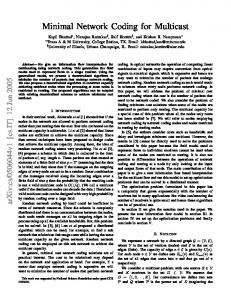
Figure 2: Elmo’s p-rule and header format. Example. Throughout this section, we use a three-tier multi-rooted Clos topology (Figure 3) with a multicast group spanning three pods—marked in orange, as a running example. The topology consists of four core switches and pods, and two spine and leaf switches per pod. Each leaf switch further connects to eight hosts. 3.1.1 Encoding switch output ports in a bitmap. Each p-rule uses a simple bitmap to represent the set of switch output ports that should forward the packet. Using a bitmap is desirable for two main reasons. First, a bitmap is the internal data structure that network switches use to direct a packet to multiple output ports [47]. Second, leaf switches typically either have many output ports in the set or are not even part of the multicast tree. This happens because cloud providers typically place a tenant’s VMs under the same leaf or spine switch to reduce bandwidth overhead for crossVM communication [45, 46]. Alternative encoding strategies would identify the set of output ports using bit strings (indicating group members) [44], bloom filters (carrying link memberships) [42, 43], or using lists of output port identifiers. However, these representations complicate packet processing in the network switches, and are not efficient for large sets of output ports (§6). With bitmap encoding, the p-rule for L5 (in Figure 3) looks like 10111011: L5. Each bit corresponds to an output port on the given switch, indicating which ports are participating in the multicast tree.
ENCODING MULTICAST TREES
Upon receiving a multicast data packet, a switch must identify what set of output ports (if any) to forward the packet while ensuring it is sent on every output port in the tree and as few extra ports as possible. In this section, we first describe how to represent multicast trees efficiently, by capitalizing on the structure of data centers (topology and tenant VM placement) and capabilities of programmable switches (flexible parsing and forwarding).
3.1
downstream bits
1
p-rule format:
Network switch. Upon receiving a multicast data packet, a physical switch running inside the network simply parses the header to look for a matching p-rule (i.e., a p-rule containing the switch’s own identifier) and forwards the packet to the associated output ports. When a multicast tree is too large to encode entirely in the packet header, a network switch may have its own flow rule (called a switch rule, or s-rule). As such, if a packet header contains no matching p-rule, the network switch checks for an s-rule matching the destination IP address (multicast group) and forwards the packet accordingly. If no matching s-rule exists, the network switch forwards the packet based on a default p-rule—the last p-rule in the packet header. Network switches have a relatively small number of s-rules, consistent with the relatively small flow tables available in high-speed hardware switches [31– 33]. The network switches in data centers form a symmetric topology (e.g., Clos) with leaf, spine, and core switches that enable Elmo to encode multicast trees efficiently.
3
0
Simple and Compact Packet Headers
Elmo encodes a multicast forwarding policy efficiently in a packet header as a list of p-rules (Figure 2: header format). Each p-rule consists of an output port bitmap along with zero or more switch identifiers (Figure 2: p-rule format). Network switches inspect the list of p-rules to decide how to forward the packet, popping p-rules when they are no longer needed to save bandwidth. We introduce five key design decisions that make our p-rule encoding both compact and simple for switches to process. 3
Upstream p-rules
Downstream p-rules Multicast Tree
00-1-00
S0
00010111-1-00
L0
P0 10
C0
S1
S2
L1
L2
C1 P1
Logical Core
C3
C2
S3
S4
L3
L4
10010111
P2 01
1011 1011
S5
S6
L5
L6
10111011
Redundancy: R = 0 s-rules = 0 s-rules = 1
P3 11
S7 L7
10011101 10111110
Sender Logical Spines: P0, P1, P2, and P3 Receiver - Ports are numbered counter clockwise, starting at the first downstream port.
10:[P0] 01:[P2] 11:[P3] 10010111:[L0] 10111011:[L5] 10111111:[L6,L7]
10:[P0] 01:[P2] 11:[P3]
R = 2 s-rules = 0, 1 10:[P0] 11:[P2,P3]
10010111:[L0] 10011111:[L0,L6] 10111011:[L5] 10111111:[L5,L7] 10011101:[L6] 10111110:[L7]
Common Parameters: p-rules = 2 (and two switches per p-rule), default p-rule
Figure 3: An example multicast tree on a three-tier multi-rooted Clos topology with upstream and downstream p- and s- rules assignment for a group. Having a separate p-rule—with a bitmap and an ID for each switch—for the multicast group in our example threetier Clos topology (Figure 3) needs a header size of 145 bits. We use two bits for identifying core switches and three bits for both spine and leaf switches.
ID list, as discussed earlier. A flag bit indicates whether a switch should use the configured multipath scheme (e.g., ECMP, CONGA [60], or HULA [61]) to forward packets to the next layer without interpreting the upstream bits. The upstream bits are used in forwarding packets upstream to multiple spine and core switches, in cases, where no single spine or core has connectivity to all members of a multicast group (§3.3).
3.1.2 Encoding on the logical topology. Instead of having separate p-rules for each switch in the multicast tree, Elmo exploits the symmetry, layered architecture, and short path lengths1 in today’s multi-rooted, data-center topologies to reduce the number of required p-rules. In multi-rooted Clos topologies, like in our example topology (Figure 3), leafto-spine and spine-to-core links use multipathing. All spine switches in the same pod behave as one giant logical switch, and all core switches together behave as one logical core switch. We refer to the logical topology as one where there is a single logical spine switch per pod, and a single logical core switch connected to pods. We order p-rules inside a packet by layer according to the following topological ordering: upstream (leaf and spine), core, and downstream (spine and leaf), as shown in Figure 2: header format. With this grouping, only the switches within the same layer share bitmaps (§3.1.3); doing so also accounts for varying switch port densities per layer. Organizing prules by layers together with the other characteristics of the logical topology allow us to further reduce header size and traffic overhead in four key ways:
3. A multicast packet visits a layer only once, both in its upstream and downstream path. The only switches that require upstream ports represented in their bitmaps are the leaf and spine switches in the upstream path. The bitmaps of all other switches, therefore, only require their downstream ports represented using bitmaps. The shorter bitmaps for these switches, therefore, reduce space usage even further. Note, upstream bitmaps will differ based on the source, whereas, downstream bitmaps remain identical. 4. Lastly, grouping p-rules by layer allows switches to pop all headers of that layer when forwarding a packet from one layer to another. This is again possible because a packet visits each layer only once in its upstream and downstream path, and a switch can therefore safely remove p-rules irrelevant to subsequent layers in the path. This also exploits the capability of programmable switches to decapsulate headers at line rate, discussed in detail in §4. Doing so further reduces traffic overhead. In our example (Figure 3), encoding on the logical topology drops the header size to 76 bits (a reduction of 47.59% from §3.1.1).
1. We only require one p-rule per logical switch, with all switches belonging to the same logical group using not only the same bitmap to send packets to output ports, but also requiring only one logical switch identifier in the p-rule.
3.1.3 Sharing a bitmap across switches. Even with logical topology, having a separate p-rule for each switch in the downstream path could lead to very large packet headers, imposing bandwidth overhead on the network. In addition, network switches have restrictions on the packet header
2. For switches in the upstream path (i.e., when packets traverse from the host upwards to the leaf, logical spine, and logical core), p-rules contain only the bitmaps without a switch 1 e.g.,
a maximum of five hops in the Facebook Fabric topology [50] 4
sizes they can parse (e.g., 512 bytes [47]), limiting the number of p-rules we can encode in each packet. To further reduce header sizes, Elmo can assign multiple switches to the same p-rule, at each layer, if the switches have the same— or similar—bitmaps. Mapping multiple switches to a single bitmap reduces header sizes because the output bitmap of a rule requires more bits to represent than switch identifiers; for example, a datacenter with 27K hosts has approximately 1000 switches (needing 10 bits), whereas switch port densities range from 48 to 576 (requiring that many bits) [60]. The algorithm to identify sets of switches with similar bitmaps is described in §3.2. We encode the set of switches as a simple list of switch identifiers, as shown in Figure 2: p-rule format. Alternate encodings, such as bloom filters [62], are more complicated to implement—requiring a switch to account for false positives, where multiple p-rules are a “match.” To keep false-positive rates manageable, these approaches lead to large filters [24], which is less efficient than having a list, as the number of switches with similar bitmaps are relatively small compared to the total number of switches in the data-center network. With p-rule sharing, such that the bitmaps of assigned switches differ by at most two bits (i.e., R = 2, §3.2.1), logical switches P2 and P3 (in Figure 3) share a p-rule at the spine layer. At the leaf layer, L0 shares a p-rule with L6 and L5 with L7. This further brings down the header size to 58 bits (a decrease of 23.68% from §3.1.2).
by other p-rules. However, the use of the default p-rule results in extra packet transmissions that increase traffic overhead. To reduce the traffic overhead without increasing header size, we exploit the fact that switches already support multicast group tables. Each entry, an s-rule, in the table matches a multicast group identifier and sends a packet out on multiple ports. Before assigning a switch to a default p-rule for a multicast group, we first check if the switch has space for an s-rule. If so, we install an s-rule in that switch, and assign only those switches to the default p-rule that have no spare s-rule capacity. For example, in Figure3, with s-rule capacity of one entry per switch (and R equals zero), both leaf switches L6 and L7 now have an s-rule entry instead of the default p-rule, as in the previous case (§3.1.4).
3.2
Generating p- and s-Rules
Having discussed the mechanisms of our design, we now explain how Elmo expresses a group’s multicast tree as a combination of p- and s-rules. The algorithm is executed once per layer for each group. The input to the algorithm is a set of switch IDs and their output ports for a multicast tree (input bitmaps). 3.2.1 Constraints. Every layer needs its own p-rules. Within each layer, we ensure that no more than Hmax p-rules are used. We budget a separate Hmax per layer such that the total number of p-rules is within a header size limit. This is straightforward to compute because (i) we bound the number of switches per p-rule to Kmax —restricting arbitrary number of switches from sharing a p-rule and inflating the header size—so the maximum size of each p-rule is known, and (ii) the number of p-rules required in the upstream direction is known, leaving only the downstream spine and leaf switches. Of these, downstream leaf switches use most of the header capacity (§5). We ensure that a network switch is assigned at most Fmax s-rules, a shared constraint across all multicast groups. For p-rule sharing, we identify groups of switches to share an output bitmap where the bitmap is the bitwise OR of all the input bitmaps. To reduce traffic overhead, we bound the total number of spurious transmissions resulting from a shared p-rule to R, where R is computed as the sum of Hamming Distances of each input bitmap to the output bitmap.
3.1.4 Dealing with limited header space using default p-rules. Default p-rules act as a mechanism to limit the total number of p-rules in the header. A default p-rule accommodates all switches that are not shared with other switches using the p-rule sharing technique (§3.1.3). For example, in Figure 3, with R equals zero and no s-rules, leaf switches L6 and L7 both get assigned to a default p-rule. The default p-rule is analogous to the lowest priority rule in the context of a flow table. It is appended after all the other p-rules in the packet, as shown in Figure 2: header format. Default p-rules are also organized by layer. The output bitmap for a default p-rule is computed as the bitwise OR of port memberships of all switches being mapped to the default rule. In the limiting case, the default p-rule causes a packet to be forwarded out of all output ports connected to the next layer at a switch (packets only make progress to the destination hosts). Thereby, increasing traffic overhead because of the extra transmissions.
3.2.2 Clustering algorithm. The problem of determining which switches share a p-rule maps to a well-known MIN-K-UNION problem, which is NP-hard [63]. Given the set of bitmaps B = {b1 , b2 , . . . , bn }, the goal is to find K sets such that the cardinality of their union is minimized. In our case, a set is a bitmap—indicating the presence or absence of a port in a switch—and the goal is to find K such bitmaps whose bitwise-OR yields the minimum number of set bits.
3.1.5 Reducing traffic overhead using s-rules. Combining all the techniques discussed till now allows Elmo to represent any multicast tree without using any state in the network switches. This is made possible because of the default p-rules, which accommodate any switches not captured 5
Algorithm 1 Clustering algorithm for each layer of a group
1: 2: 3: 4: 5: 6: 7: 8: 9: 10: 11: 12: 13: 14: 15:
used by Portland [51] and therefore do not expand on it in this paper. In effect, for a multicast group G, upstream bits are set to forward packets to one or more spines (and cores) such that the union of reachable hosts from the spine(s) (and core(s)) covers all the recipients of G.
Constants: R, Hmax , Kmax , Fmax Inputs: Set of all switches S, Bitmaps B = bi ∀i ∈ S Outputs: p-rules, s-rules and default-p-rule p-rules ← ∅, s-rules ← ∅, default-p-rule ← ∅ unassigned ← B, K ← Kmax while unassigned , ∅ and |p-rules| < Hmax do bitmaps ← min-k-union(K, unassigned) output-bm ← Bitwise OR of all bi ∈ bitmaps if dist(bi , output-bm) ≤ R ∀ bi ∈ bitmaps then p-rules ← p-rules ∪ bitmaps unassigned ← unassigned \ bitmaps else K ←K −1 for all bi ∈ unassigned do if switch i has |s-rules| < Fmax then s-rules ← s-rules ∪ {bi } else default-p-rule ← default-p-rule ∪ {bi } return p-rules, s-rules, default-p-rule
4
In this section, we describe how we implement Elmo to run at line rate on both hypervisor and network switches. Our implementation assumes that the data center is running programmable switches like PISCES [59] and Barefoot Tofino [48]. Having so entails multiple challenges for programmable switches to efficiently parse, match, and act on p-rules.
4.1
Realizing on Network Switches
In network switches, typically, a parser first extracts packet headers and then forwards them to the match-action pipeline for processing. This model works well for network protocols (like MAC learning, IP routing, and more) that use a header field to lookup match-action rules in large flow tables. In Elmo, on the other hand, we find a matching p-rule from within the packet header itself. Using match-action tables to perform this matching is prohibitively expensive (§4.1.1). Instead, we present an efficient implementation by exploiting the match-and-set capabilities of parsers in modern programmable data planes (§4.1.2).
Algorithm 1 shows our solution. For each group, we assign p-rules until Hmax p-rules are assigned or all switches have been assigned p-rules (Line 3). For p-rule sharing, we apply a MIN-K-UNION algorithm to find a group of K input bitmaps (Line 4) [63]. We then compute the bitwise OR of these K bitmaps to compute the resulting output bitmap (Line 5). If the output bitmap satisfies the traffic overhead constraint, we assign the K switches to a p-rule and remove them from the set of unassigned switches, and continue at Line 3. Otherwise, we decrement K and try to find smaller groups (Line 6). When K = 1, any unassigned switches receive a p-rule each. At any point if we encounter the Hmax constraint, we fallback to computing s-rules for any remaining switches (Line 13). If the switches do not have any s-rule capacity left, they are mapped to the default p-rule (Line 15).
3.3
IMPLEMENTING ELMO ON PROGRAMMABLE SWITCHES
4.1.1 p-rule lookups using match-action stages is expensive – strawman. Lookups in network switches are typically done using match-action tables, after the parser. We could do the same for p-rules, but using match-action tables to lookup p-rules would result in inefficient use of switch resources. Unlike s-rules, p-rules are headers. Hence, to match on p-rules, we need a table that matches on all p-rule headers. In each flow rule, we only match the switch ID with one p-rule, while wildcarding the rest. This is a constraint of match-action tables in switches that we cannot avoid. To match n p-rules, we need same number of flow-rule entries. The fundamental problem here is that instead of increasing the depth, p-rules increase the width of a table. Modern programmable data planes can store millions of flow-table entries (depth). However, they are severely limited by the number of headers they can match on in a stage (width). For example, in case of RMT [47], a match-action stage consists of 106 1K x 112b SRAM blocks and 16 2K x 40b TCAM blocks. These blocks can combine together to build wider or deeper SRAMs and TCAMs to make larger tables. For example, to implement a table that matches on ten p-rules, each 11-bit wide, we need three TCAM blocks (as we need wildcards) to cover 110b for the match. This results in a table of 2K
Ensuring Reachability via Upstream Bits under Link Failures
When the controller detects link failures, it recomputes pand s-rule assignments for any affected groups. Here, link failures affecting a multicast tree in the downstream direction (core to spines or spines to leaf) deserve special attention. In this scenario, a packet in the upstream direction cannot be routed to any spine or core switch using the underlying multipath scheme. The controller therefore deactivates multipathing (§3.1.2) for a group—if link failures affect a path in the downstream direction—by disabling the flag bit in the upstream p-rules (Figure 2: bitmap format). Furthermore, to identify the set of possible paths that cover all members of a group, we reuse the same greedy set-cover technique as 6
entries x 120b wide. And out of these 2K entries, we only use ten entries to match the respective p-rules. Thus, we end up using three TCAMs for ten p-rules while consuming only 0.5% of entries in the table, wasting 99.5% of the entries (which cannot be used by any other stage). An alternative to using TCAMs for p-rule lookups is to eschew wildcard lookups and use SRAM blocks. In this case, a switch needs n stages to lookup n p-rules in a packet, where each stage only has a single rule. This too is prohibitively expensive. First, the number of stages in a switch is limited (RMT has 16 stages for the ingress pipeline). Second, as with TCAMs, 99.9% of the SRAM entries go to waste, as each SRAM block is now used only for a single p-rule each (out of 1K available entries per block).
The queue manager generates the desired copies of the packet and forwards them to the egress pipeline [47]. At the egress pipeline, we execute the following post-processing checks. For leaf switches, if a packet is going out towards the host, the egress pipeline invalidates all p-rules indicating the de-parser to remove these rules from the packet before forwarding it to the hosts. This offloads the burden at the receiving hypervisor switches, saving unnecessary cycles spent to decapsulate p-rules. Otherwise, the egress pipeline invalidates all p-rules up to the p-rules(s) of the next-hop switch before forwarding the packet.
4.2
Realizing on Hypervisor Switches
In hardware switches, representing each p-rule as a separate header is required to match p-rules in the parsing stage. However, using the same approach for the hypervisor switch (like PISCES [59]) reduces throughput because each header copy triggers a separate DMA write call. Instead, to operate at line rate, we treat all p-rules as one header and encode it using a single write call (§5.4). Not doing so, decreases throughput linearly with increasing number of p-rules to pack.
4.1.2 Matching p-rules using parser. Instead of using a match-action table to lookup p-rules, the switch can scan the packet as it arrives at the parser. The parser linearly traverses the packet header and stores the bits in a header vector based on the configured parse graph. Parsers in programmable data planes provide support for setting metadata at each stage of the parse graph. Hence, enabling basic match-and-set lookups inside the parsers. Elmo exploits this property, augmenting the parser to check at each stage—when parsing p-rules—to see if the ID of the given p-rule matches the switch ID. If it does, the parser stores the p-rule’s bitmap in a metadata field and skips parsing remaining p-rules and jumps directly to the next header (if any). The parser parses the list of p-rules until it reaches a rule with “next” flag set to 0 (Figure 2: p-rule format), or the default p-rule. By matching p-rules inside the parser, we no longer require a match-action stage to search p-rules at each switch, thus, making switch’s memory resources available for other use, including s-rules. However, the size of a header vector (i.e., the maximum header size a parser can parse) in programmable chips is also fixed. For RMT the size is 512 bytes. We show in Section 5.2, how Elmo’s encoding scheme easily fits enough p-rules within 325 bytes while supporting millions of groups.
5
EVALUATION
In this section, we evaluate the scalability and resource requirements of Elmo. Table 1 summarizes our results.
5.1
Hardware Resource Requirements
We study the hardware resource requirements of switching ASICs to process p-rules. We found Elmo inexpensive to implement in modern switching ASICs. 5.1.1 Header usage with varying number of p-rules. Figure 4 shows percentage header usage—for a chip that can parse a 512-byte packet header e.g., RMT [47]—as we increase the number of p-rules. Each p-rule consists of four bytes for switch IDs and a 48-bit bitmap. With 30 p-rules, we are still well within the range, consuming only 63.5% of header space for p-rules with 190 bytes for other protocols; in enterprises [65] and data centers [66] that take about 90 bytes [64]. We evaluated these results using the open-source compiler for P4’s behavioral model (i.e., bmv1 [67]). Also, a parser parsing 30 headers (i.e., p-rules in our case) consumes about 45% of its TCAM resources [64].
4.1.3 Forwarding based on p- and s-rules. After parsing the packet, the parser forwards metadata to the ingress pipeline, which includes a bitmap, a matched flag (indicating the presence of a valid bitmap), and a default bitmap. The ingress pipeline implements the control flow to check for the following cases: If the matched flag is set, write the bitmap metadata to the queue manager [47], using a bitmap_port_select primitive (§5.1.2). Else, lookup the group table using the destination IP address for an s-rule. If there is a match, write the s-rule’s group identifier to the queue manager, which then converts it to a bitmap. Otherwise, use the bitmap from the default p-rule.
5.1.2 Enabling bitmap-based output port selection. Network switches already use an output port bit vector, internally, for replicating packets [47]. However, it’s not yet exposed as a metadata field that the parser can set. We add support for specifying this bit vector using a new primitive action in P4 [54]. We call this new primitive bitmap_port_select. It takes a bitmap of size n as input and sets the output port 7
Hardware resource requirements: Elmo is inexpensive to implement in switching ASICs (§5.1)
For a 256-port, 200 mm 2 baseline switching ASIC that can parse a 512-byte packet header [64], Elmo consumes only 63.5% of header space even with 30 p-rules (Figure 4), and its primitives add only 0.0515% in area and 176 mW in power costs (Figures 5 and 6).
Scalability: Elmo scales to millions of multicast groups with minimal flow-table usage and control-plane update overhead on network switches (§5.2.2)
In a multi-rooted Clos topology with 27K hosts and 1M multicast groups, with group sizes based on a production trace: (i) 95-99% of groups can be encoded using a 325-byte p-rule header (Figure 7 and Figure 8, left). (ii) Spine and leaf switches use only a mean (max) of 3.8K (11K) and 1.1K (2.9K) s-rules (Figure 7 and Figure 8, center). (iii) Traffic overhead is kept within 34% and 5% of the ideal for 64-byte and 1,500-byte packets (Figure 7 and Figure 8, right). (iv) On average, a membership update to a group triggers an update to 50% of hypervisor switches, less than 0.006% of leaf and 0.002% of spine switches relevant to that group’s multicast tree.
Applications remain unmodified, and benefit from reduced CPU and bandwidth utilization for multicast workloads (§5.3)
We run ZeroMQ (a publish-subscribe system) and sFlow (a monitoring application) on top of Elmo. Elmo enables these systems to scale to hundreds of receivers while maintaining constant CPU and bandwidth overhead at the transmitting VM (Figure 9).
End-host resource requirements: Elmo adds negligible overheads to hypervisor switches (§5.4)
A PISCES-based hypervisor switch encapsulates p-rules and forwards packets at line rate on a 20 Gbps link (Figures 10).
Header size (bytes)
Table 1: Summary of results.
600
of the ingress pipeline, and up to the queue manager in an RMT-style switching ASIC [47, 48]. We compute the resource requirements for four switch-port counts: 32, 64, 128, 256. We quantify the area cost and power requirements of adding the multiplexer and shift register blocks. We evaluate the area cost against a 200 mm 2 baseline switching chip (assuming a lower-end chip and the smallest area given by [64]). Figure 5 shows that the added area cost for a multiplexer block is a nominal 0.0015% (2,984 um2 ) for passing a 256bit wide vector to the queue manager (and a corresponding 5.31 mW in power). Using a shift-register further (Figure 6) increases the area usage by 0.05% (114,150.12 um2 ) for 256bit wide bit vectors for a 32 stage pipeline (and 171.11 mW in power). As another point of comparison for the reader, CONGA [60] and Banzai [72] consume an additional 2% and 12% area, respectively. The circuit delay for the multiplexer is 120 ps (mean) for each of the four tested port counts. The circuit delay of a single stage in shift register is 150ps (mean).
Header size limit for RMT (512B)
400 200 0 0
5
10
15
20
25
30
No. of p−rules
Figure 4: Header usage with varying number of prules, each having four bytes for switch IDs and 48 bits for bitmap along with a default p-rule. (Horizontal dashed line shows the maximum header space of 512 bytes for RMT [47].) bit vector field that a queue manager uses to generate copies of a packet, routed to each egress port. The function is executed by a match-action stage in the ingress pipeline before forwarding the packet to the queue manager. We evaluate the output port selection primitive using Synopsys 28/32 nm standard cell technology [68], synthesized with a 1 GHz clock. All configurations meet the timing requirements at 1 GHz. A typical ASIC implements multicast using a group table that maps a group ID to a bit vector [69–71]. The multiplexer block represents the hardware requirement to pass the bit vector directly to the queue manager in such ASICs. The shift register on the other hand, shows the hardware required to pass the bit vector from the parser, through all stages
5.2
Scalability
5.2.1 Experiment setup. We now describe the setup we use to test the scale of the number of multicast groups Elmo can support and the associated traffic overhead. Topology. The scalability evaluation relies on a simulation over a large data-center topology; the simulation places VMs belonging to different tenants on end hosts within the data 8
Power (mW)
Area (%)
0.0015 0.0010 0.0005 0.0000 32
64
sizes, scaled by the tenant’s size. Each group’s member (i.e., a VM) is randomly selected from the VMs of the tenant. The minimum group size is five. We use the group-size distributions described in the Multicast DCN paper [24]. We model the first distribution by analyzing the multicast patterns of an IBM WebSphere Virtual Enterprise (WVE) deployment, with 127 nodes and 1,364 groups. The average group size is 60, and nearly 80% of the groups have fewer than 61 members, and about 0.6% have more than 700 members. The second distribution generates tenant’s groups’ sizes that are uniformly distributed between the minimum group size and entire tenant size (Uniform).
4 2 0
128 256
32
64
Ports
128
256
Ports
Figure 5: Multiplexer area (in um2 ) assuming a 200 mm 2 area chip [64] and power (mW) for different switchport counts. 1 8 16
32
Stages
Power (mW)
Area (%)
Stages
0.04 0.02 0.00 32
64
128
Ports
256
1 8 16
32
5.2.2 Elmo scales to millions of multicast groups with minimal flow-table usage. We first describe results for the various placement strategies under the IBM’s WVE group size distribution. We cap the p-rule header size at 325 bytes per packet, which allows up to 30 p-rules for the downstream leaf layer and two for the spine layer. We vary the number of redundant transmissions (R) permitted due to p-rule sharing. We evaluate (i) the number of groups covered using only the non-default p-rules, (ii) the number of s-rules installed, and (iii) the total traffic overhead incurred by introducing redundancy via p-rule sharing and default p-rules. Figure 7 shows groups covered with non-default p-rules, s-rules installed per switch, and traffic overhead for a placement policy that packs up to 12 VMs of a tenant per rack (P = 12). p-rules suffice to cover a high fraction of groups; 89% of groups are covered even when using R = 0, and 99.78% with R = 12. With VMs packed closer together, the allocated p-rule header sizes suffice to encode most multicast trees in the system. Figure 7 (left) also shows how increasing the permitted number of extra transmissions with p-rule sharing allows more groups to be represented using only p-rules. Figure 7 (center) shows the trade-off between p-rule and srule usage. With R = 0, p-rule sharing tolerates no redundant traffic. In this case, p-rules comprise only of switches having exactly same bitmaps; as a result, the controller must allocate more s-rules, with 95% of leaf switches having fewer than 4,059 rules (mean 1,059). Increasing R to 6 and 12 drastically decreases s-rule usage as more groups are handled using only p-rules. With R = 12, switches have on average 2.74 rules, with a maximum of 107. Figure 7 (right) shows the resulting traffic overhead assuming 1,500-byte packets. With R = 0 and sufficient s-rule capacity, the resulting traffic overhead is identical to ideal multicast. Increasing R increases the overall traffic overhead to 5% of the ideal. Overhead is modest because even though a data packet may have as much as 325 bytes of p-rules at the source, p-rules are removed from the header with every hop (§3.1), reducing the total traffic overhead. For 64-byte
150 100 50 0 32
64
128
256
Ports
Figure 6: Shift-register area (in um2 ) assuming a 200 mm2 area chip [64] and power (mW) for different switch-port counts. center and assigns multicast groups of varying sizes to each tenant. We simulate using a Facebook Fabric topology—a three-tier topology—with 12 pods [50]. A pod contains 48 leaf switches each having 48 ports. Thus, the topology with 12 pods supports 27,648 hosts, in total. (We saw qualitatively similar results while running experiments for a two-tier leafspine topology like that used in CONGA [60].) Tenant VMs and placement policy. Mimicking the experiment setup from Multicast DCN [24], the simulated data center has 3,000 tenants. The number of VMs per tenant follows an exponential distribution, with min=10, median=97, mean=178.77, and max=5,000. We assign at most 20 VMs to each host. A tenant’s VMs do not share the same physical host. We use a placement strategy where we first select a pod uniformly at random, then pick a random leaf within that pod and pack up to P VMs of that tenant under that leaf. P regulates the degree of co-location in the placement. We evaluate for P = 1 and P = 12 to simulate both dispersed and clustered placement policies. If the chosen leaf (or pod) does not have any spare capacity to pack additional VMs, the algorithm selects another leaf (or pod) until all VMs of a tenant are placed. Multicast Groups. We assign multicast groups to each tenant such that there are a total of one million groups in the data center. The number of groups assigned to each tenant is proportional to the size of the tenant (i.e., number of VMs in that group). We use two different distributions for groups’ 9
750K
500K
250K
0
Traffic Overhead (ratio with ideal multicast)
s−rules installed per switch
Groups covered with p−rules
1M
4K 3K 2K 1K 0
(center), with 95% of switches having fewer than 2,435 srules. The traffic overhead increases to within 25% of the ideal when R = 12, but still improving significantly over overlay multicast (92%) and unicast (406%).
4 3 2
p-rule sharing is robust to different group size distributions. We also study how the results are affected by different distributions of group sizes, using the Uniform group size distribution. We expect that larger group sizes will be more difficult to encode using only p-rules. We found that with the P = 12 placement policy, the total number of groups covered using only p-rules drops to 814K at R = 0 and to 922K at R = 12. When spreading VMs across racks with P = 1, only 250K groups are covered by p-rules using R = 0, and 750K when R = 12. The total traffic overhead for 1,500-byte packets in that scenario increases to 11%.
1 0
0 6 12 Redundancy limit (R)
0 6 12 Redundancy limit (R)
0 6 12 Redundancy limit (R)
750K
500K
250K
0 0 6 12 Redundancy limit (R)
20K
Traffic Overhead (ratio with ideal multicast)
1M
s−rules installed per switch
Groups covered with p−rules
Figure 7: Placement policy with no more than 12 VMs of a tenant per rack. (Left) Number of groups covered using non-default p-rules. (Center) s-rules usage across switches. (Right) Traffic overhead relative to ideal (horizontal dashed lines show unicast (top) and overlay multicast (bottom)).
15K
10K
5K
0
Reducing s-rule capacity increases default p-rule usage if p-rule sizes are insufficient. Limiting the s-rule capacity of switches allows us to study the effects of limited switch memory on the efficiency of the encoding scheme. Doing so increases the number of switches that are mapped to the default p-rule. When limiting the s-rules per switch to 10K rules, and using the extreme P = 1 placement policy, the uniform group size distribution experiences higher traffic overheads, approaching that of overlay multicast at R = 0 (87% vs 92%), but still being only 40% over ideal multicast at R = 12. Using the WVE distribution however, brings down traffic overhead to 19% and 25% for R = 6 and R = 12, respectively. With the tighter placement of P = 12, however, we found the traffic overhead to consistently stay under 5% regardless of the group-size distribution.
4
3
2
1
0 0 6 12 Redundancy limit (R)
0 6 12 Redundancy limit (R)
Figure 8: Placement policy with no more than 1 VM of a tenant per rack. (Left) Number of groups covered using non-default p-rules. (Center) s-rules usage across switches. (Right) Traffic overhead relative to ideal (horizontal dashed lines show unicast (top) and overlay multicast (bottom)).
Reduced p-rule header sizes and s-rule capacities inflate traffic overheads. Finally, to study the effects of the size of the p-rule header, we reduced the size so that the header could support at most 10 p-rules for the leaf layer (i.e., 125 bytes per header). In conjunction, we also reduced the s-rule capacity of each switch to 10K and used the P = 1 placement policy to test a scenario with maximum dispersement of VMs. This challenging scenario even brought the traffic overhead to exceed that of overlay multicast at R = 12 (123%). However, in contrast to overlay multicast, Elmo still forwards packets at line rate.
packets, the traffic overhead for WVE increases only to 29% and 34% of the ideal when R = 0 and R = 12, still significantly improving over overlay multicast (92%) and unicast (406%). p-rule sharing is effective even when groups are dispersed across leaves. Thus far, we discussed results for when up to 12 VMs of the same tenant were placed in the same rack. To understand how our results vary for different VM placement policies, we explore an extreme case where the placement policy spreads VMs across leaves, placing no more than a single VM of a tenant per rack. Figure 8 (left) shows this effect. Dispersing groups across leaves requires larger headers to encode the whole multicast tree using only p-rules. Even in this case, p-rules with R = 0 can handle as many as 750K groups, since 77.8% of groups have less than 36 switches, and there are 30 p-rules for the leaf layer—just enough header capacity to be covered only with p-rules. Increasing R to 12 ensures that 95.9% of groups are covered using p-rules. We see the expected drop in s-rule usage as well in Figure 8
5.2.3 Elmo reduces control-plane update overhead on network switches and directs updates to hypervisor switches instead. We use the same Facebook Fabric setup to evaluate the effects of membership dynamics. There are three types of members: senders, receivers, or both. For this evaluation, we randomly assign one of these three types to each member. All VMs of a tenant who are not a member of a group have equal probability to join; similarly, all existing members of the group have an equal probability of 10
0.3351 0.4999 0.0042 0.0061 0.0015 0.0023
● ●
●
●
●
●
●
●
Unicast
●
●
●
●
●
●
●
●
● ●
Number of subscribers
Table 2: Average number of updates per event for hypervisor, leaf, and spine switches, normalized by group sizes. Results are shown for WVE distribution.
Elmo
Unicast
100 75 50 25 0
Number of subscribers
Figure 9: Requests-per-second and CPU utilization comparison of a pub-sub application using ZeroMQ for both unicast and Elmo.
leaving. Join and leave events are generated randomly, and the number of events per group is proportional to the group size. If a member is a sender, the controller only updates the source hypervisor switch. By design, Elmo only uses s-rules if the p-rule header capacity is insufficient to encode the entire multicast tree of a group. Membership changes trigger updates to sender and receiver hypervisor switches depending on whether upstream or downstream p-rules need to be updated. When a membership change affects s-rules, it triggers updates to the leaf and spine switches. Table 2 shows the results for one million join/leave events with one million multicast groups, where no more than one VM of a tenant is placed per rack. On average, a membership change to a group triggers an update to 50% of hypervisor switches, fewer than 0.006% of leaf and 0.002% of spine switches relevant to that group’s multicast tree, demonstrating that hypervisor switches handle most of Elmo’s controlplane updates.
Xeon(R) CPUs running at 2.00 GHz and with 32 GB of memory. Each of the three switch machines runs the PISCES [59] switch for routing traffic between interfaces. The host machines use one dual-port Intel 82599ES 10 Gigabit Ethernet NIC each. 5.3.1 Publish-subscribe using ZeroMQ. We implement a publish-subscribe (pub-sub) system using ZeroMQ. ZeroMQ enables tenants to build pub-sub systems on top of a cloud environment (like AWS [73], GCP [74], or Azure [75]), by establishing unicast connections (e.g., TCP or UDP) between publishers and subscribers. Throughput (rps). Figure 9 (left) shows the throughput comparison in requests per second. With unicast, the throughput at subscribers decreases with an increasing number of subscribers because the publisher becomes the bottleneck; the publisher services a single subscriber at 185K rps on average and drops to about 0.25K rps for 256 subscribers. With Elmo, the throughput remains the same regardless of the number of subscribers and averages 185K rps throughout.
5.2.4 Elmo’s controller computes p- and s-rules for a group in tens of micro-seconds. Our controller consistently executes Algorithm 1 for computing p- and s-rules in tens of microseconds. Across our simulations, our Python implementation computes the required rules for groups in 0.60 µs ± 32µs on average for all the computed group sizes, for a header size limit of 325 bytes. These performance numbers indicate that Elmo’s control logic is fast enough to support the needs of large data centers today, even before extensive optimization.
5.3
200K 150K 100K 50K 0K
●
1 2 4 8 16 32 6 124 258 6
spine
Elmo
●
CPU Utilization (%)
leaf
join leave join leave join leave
# U pd at es G r oup S iz e
1 2 4 8 16 32 6 124 258 6
hypervisor
event
Throughput (rps)
switch
CPU utilization. The CPU usage of the publisher VM also increases with increasing number of publishers, Figure 9 (right). The publisher VM consumes 32% of the VM’s CPU with 64 subscribers and saturates the CPU with 256 subscribers onwards. With Elmo, the CPU usage remains constant regardless of the number of subscribers (i.e., 4.97%). 5.3.2 Host telemetry using sFlow. As our second application, we compare the performance of host telemetry using sFlow with both unicast and Elmo. sFlow exports physical and virtual server performance metrics from sFlow agents to collector nodes (e.g., CPU, memory, and network stats for docker, KVMs, and hosts) set up by different tenants (and teams) to collect metrics for their needs. We compare the egress bandwidth utilization at the host of the sFlow agent with increasing number of collectors, using both unicast and Elmo. The bandwidth utilization increases linearly with
Evaluating End-to-end Applications
We ran two popular data-center applications on top of Elmo: ZeroMQ [15] and sFlow [3]. We found that these applications ran unmodified on top of Elmo and benefited from reduced CPU and bandwidth utilization for multicast workloads. Testbed Setup. The topology for this experiment comprises nine PowerEdge R620 servers having two eight cores Intel(R) 11
Throughput (Gbps)
Throughput (Mpps)
15 10 5 0 0
5
10 15 20 25 30
No. of p−rules
The data center, however, differs in significant ways from the wide-area context. With SDN-based data centers, a single administrative domain has control over the entire topology and is no longer required to run the decentralized protocols like IGMP and PIM. However, SDN-based multicast is still bottlenecked by limited switch flow-table capacities [31–33]. Approaches to scaling multicast groups in this context have tried using rule aggregation to share multicast entries in switches with multiple groups [24, 90–92]. Yet, these solutions do not operate well in cloud environments because (1) a change in one group can cascade to other groups, (2) do not provide address-space isolation between tenants, and (3) cannot utilize the full cross-sectional bandwidth of the network [24, 51]. Elmo, on the other hand, operates on a groupby-group basis, maintains isolation by operating within tenants’ broadcast domain, and makes full use of the entire cross-sectional bandwidth. The lack of native multicast support, including among the major cloud providers [20–22], requires tenants to use inefficient software-based multicast solutions such as overlay multicast or application-layer mechanisms [15, 16, 36, 37, 93]. These mechanisms are built on top of unicast, which as we demonstrated in §5, incurs a significant reduction in application throughput and inflates CPU utilization. With native multicast, as in Elmo, end hosts send a single copy of the packet to the network and use intermediate switches to replicate and forward copies to multiple destinations. Elmo is not the first system to encode forwarding state inside packets. Previous work [42, 43, 94] have tried to encode link identifiers inside packets using bloom filters. BIER [44] encodes group members as bit strings and switches lookup these strings to identify output ports. However, these approaches require unorthodox processing at the switches (e.g., loops) and are infeasible to implement and process multicast traffic at line rate. Elmo, on the other hand, is designed to operate at line rate using modern programmable data planes (like Barefoot Tofino [48] and Cavium XPliant [49]).
20 15 10 5 0 0
5
10 15 20 25 30
No. of p−rules
Figure 10: PISCES throughput in millions of packets per second (left) and Gbps (right) when adding different number of p-rules, expressed as a single P4 header. unicast, with the addition of each new collector. With 64 collectors, the egress bandwidth utilization at the agent’s host is 370.35 Kbps. With Elmo, the utilization remains constant at about 5.8 Kbps (equal to the bandwidth requirements for a single collector).
5.4
End-host Microbenchmarks
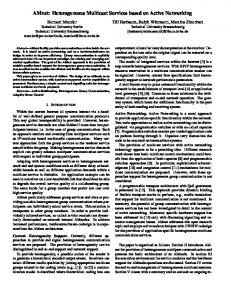
We conduct microbenchmarks to measure the incurred overheads on the hypervisor switches when encapsulating prule headers onto packets (decapsulation at every layer is performed by network switches). We found Elmo imposes negligible overheads at hypervisor switches. Setup. Our testbed has a host H 1 directly connected to two hosts H 2 and H 3. H 1 has 20 Gbps connectivity with both H 2 and H 3, via two 10 Gbps interfaces per host. H 2 is a traffic source and H 3 is a traffic sink; H1 is running PISCES with the extensions for Elmo to perform necessary forwarding. H 2 and H 3 use MoonGen [76] for generating and receiving traffic, respectively. Results. Figure 10 shows throughput at a hypervisor switch when encapsulating different number of p-rule headers, in both packets per second (pps) and Gigabits per second (Gbps). Increasing the number of p-rules reduces the pps rate, as the packet size increases, while the throughput in bps remains unchanged. The throsughput matches the capacity of the links at 20 Gbps, demonstrating that Elmo imposes negligible overhead on hypervisor switches.
6
7
CONCLUSION
In this paper, we presented Elmo, a solution to scale multicast to millions of groups per data center. Elmo encodes multicast forwarding rules in packets themselves, reducing the need to install corresponding flow-table entries in network switches. Elmo takes advantage of the unique characteristics of data-center topologies and workloads to identify compact encodings of forwarding rules inside packets; our simulations show that a 325-byte header sufficed to support a million multicast groups in a data center with 27K hosts, while using minimal flow-table entries in switches. Furthermore, Elmo is inexpensive to implement in programmable switches today and supports unmodified applications.
RELATED WORK
Multicast has been studied in detail in the context of widearea networks [77–81], where the lack of applications and architectural complexities led to limited adoption [23]. Furthermore, the decentralized protocols such as IGMP and PIM faced several control-plane challenges with regards to stability in the face of membership churn [23]. Over the years, much work has gone into IP multicast to address issues related to scalability [42, 82], reliability [83–86], security [87], and congestion control [88, 89]. 12
REFERENCES [1] Microsoft Azure, “Cloud Service Fundamentals – Telemetry Reporting.” https://azure.microsoft.com/en-us/blog/ cloud-service-fundamentals-telemetry-reporting/, 2013. [2] M. L. Massie, B. N. Chun, and D. E. Culler, “The Ganglia Distributed Monitoring System: Design, Implementation, and Experience,” Elsevier Parallel Computing, vol. 30, no. 7, pp. 817–840, 2004. [3] S. Panchen, N. McKee, and P. Phaal, “InMon Corporation’s sFlow: A Method for Monitoring Traffic in Switched and Routed Networks.” RFC 3176, Sept. 2001. [4] Open Config, “Streaming Telemetry.” http://blog.sflow.com/2016/06/ streaming-telemetry.html, 2016. [5] “Galera Cluster.” http://galeracluster.com/, 2007. [6] D. R. K. Ports, J. Li, V. Liu, N. K. Sharma, and A. Krishnamurthy, “Designing Distributed Systems using Approximate Synchrony in Data Center Networks,” in USENIX NSDI, 2015. [7] L. Lamport, “The Part-time Parliament,” ACM Transactions on Computer Systems (TOCS), vol. 16, pp. 133–169, May 1998. [8] L. Lamport, “Fast Paxos,” Springer Distributed Computing, vol. 19, no. 2, pp. 79–103, 2006. [9] “JGroups: A Toolkit for Reliable Messaging.” http://www.jgroups.org/ overview.html, 2002. [10] “Akka: Build Powerful Reactive, Concurrent, and Distributed Applications more Easily – Using UDP.” https://doc.akka.io/docs/akka/2.5.4/ java/io-udp.html, 2002. [11] L. Suresh, M. Canini, S. Schmid, and A. Feldmann, “C3: Cutting Tail Latency in Cloud Data Stores via Adaptive Replica Selection,” in USENIX NSDI, 2015. [12] Elastic, “ElasticSearch: Discovery Plugins.” https://www.elastic.co/ guide/en/elasticsearch/plugins/current/discovery.html, 2017. [13] Google, “Cloud Pub/Sub.” https://cloud.google.com/pubsub/, 2016. [14] N. Garg, Learning Apache Kafka, Second Edition. Packt Publishing, 2nd ed., 2015. [15] P. Hintjens, ZeroMQ: Messaging for Many Applications. O’Reilly Media, Inc., 2013. [16] A. Videla and J. J. Williams, RabbitMQ in Action: Distributed Messaging for Everyone. Manning, 2012. [17] Google, “Cloud Pub/Sub – Quotas.” https://cloud.google.com/pubsub/ quotas, 2016. [18] VMware, “NSX Network Virtualization and Security Platform.” https: //www.vmware.com/products/nsx.html, 2017. [19] A. Dainese, “VXLAN on VMware NSX: VTEP, Proxy, Unicast/Multicast/Hybrid Mode.” http://www.routereflector.com/2015/02/ vxlan-on-vmware-nsx-vtep-proxy-unicastmulticasthybrid-mode/, 2017. [20] Amazon Web Services (AWS), “Frequently Asked Questions.” https: //aws.amazon.com/vpc/faqs/, 2017. [21] Google Cloud Platform, “Frequently Asked Questions.” https://cloud. google.com/vpc/docs/vpc, 2017. [22] Microsoft Azure, “Frequently Asked Questions.” https://docs.microsoft. com/en-us/azure/virtual-network/virtual-networks-faq, 2017. [23] C. Diot, B. N. Levine, B. Lyles, H. Kassem, and D. Balensiefen, “Deployment Issues for the IP Multicast Service and Architecture,” IEEE Network, vol. 14, no. 1, pp. 78–88, 2000. [24] X. Li and M. J. Freedman, “Scaling IP Multicast on Datacenter Topologies,” in ACM CoNEXT, 2013. [25] B. Cain, D. S. E. Deering, B. Fenner, I. Kouvelas, and A. Thyagarajan, “Internet Group Management Protocol, Version 3.” RFC 3376, Oct. 2002. [26] B. Fenner, M. J. Handley, I. Kouvelas, and H. Holbrook, “Protocol Independent Multicast - Sparse Mode (PIM-SM): Protocol Specification (Revised).” RFC 4601, Aug. 2006. 13
[27] T. Speakman, L. Vicisano, M. J. Handley, and I. Kouvelas, “Bidirectional Protocol Independent Multicast (BIDIR-PIM).” RFC 5015, Oct. 2007. [28] H. Holbrook and S. Systems, “Source-Specific Multicast for IP.” RFC 4607, Aug. 2006. [29] A. Karan, C. Filsfils, I. Wijnands, and B. Decraene, “Multicast-Only Fast Reroute.” RFC 7431, Aug. 2015. [30] X. Wang, C. Yu, H. Schulzrinne, P. Stirpe, and W. Wu, “IP Multicast Fault Recovery in PIM over OSPF,” in IEEE ICNP, 2000. [31] Cisco, “Cisco Nexus 5000 Series - hardware multicast snooping grouplimit.” https://www.cisco.com/c/en/us/td/docs/switches/datacenter/ nexus5000/sw/command/reference/multicast/n5k-mcast-cr/ n5k-igmpsnp_cmds_h.html, 2018. [32] Network World, “Multicast Group Capacity: Extreme Comes Out on Top.” https://www.networkworld.com/article/2241579/virtualization/ multicast-group-capacity--extreme-comes-out-on-top.html, 2010. [33] Juniper, “Understanding VXLANs.” https://www.juniper.net/ documentation/en_US/junos/topics/topic-map/sdn-vxlan.html, 2018. [34] J. Jannotti, D. K. Gifford, K. L. Johnson, M. F. Kaashoek, and J. W. O’Toole, Jr., “Overcast: Reliable Multicasting with on Overlay Network,” in USENIX OSDI, 2000. [35] M. Castro, P. Druschel, A.-M. Kermarrec, A. Nandi, A. Rowstron, and A. Singh, “SplitStream: High-bandwidth Multicast in Cooperative Environments,” in ACM SOSP, 2003. [36] S. Banerjee, B. Bhattacharjee, and C. Kommareddy, “Scalable Application Layer Multicast,” in ACM SIGCOMM, 2002. [37] A. Das, I. Gupta, and A. Motivala, “SWIM: Scalable Weakly-consistent Infection-style Process Group Membership Protocol,” in IEEE DSN, 2002. [38] Y. Vigfusson, H. Abu-Libdeh, M. Balakrishnan, K. Birman, R. Burgess, G. Chockler, H. Li, and Y. Tock, “Dr. Multicast: Rx for Data Center Communication Scalability,” in ACM EuroSys, 2010. “Overlay Multicast in Amazon Virtual [39] Amazon, Private Cloud.” https://aws.amazon.com/articles/ overlay-multicast-in-amazon-virtual-private-cloud/, 2018. [40] Weave Works, “Multicasting in the Cloud.” https://www.weave.works/ use-cases/multicast-networking/, 2017. [41] Arista, “10Gb Ethernet – The Foundation for Low-Latency, Real-Time Financial Services Applications and Other, Latency-Sensitive Applications.” https://www.arista.com/assets/data/pdf/Whitepapers/Arista_ Solarflare_Low_Latency_10GbE__1_.pdf, 2018. [42] P. Jokela, A. Zahemszky, C. Esteve Rothenberg, S. Arianfar, and P. Nikander, “LIPSIN: Line Speed Publish/Subscribe Inter-networking,” in ACM SIGCOMM, 2009. [43] S. Ratnasamy, A. Ermolinskiy, and S. Shenker, “Revisiting IP Multicast,” in ACM SIGCOMM, 2006. [44] I. Wijnands, E. C. Rosen, A. Dolganow, T. Przygienda, and S. Aldrin, “Multicast Using Bit Index Explicit Replication (BIER).” RFC 8279, Nov. 2017. [45] V. Varadarajan, Y. Zhang, T. Ristenpart, and M. Swift, “A Placement Vulnerability Study in Multi-tenant Public Clouds,” in USENIX Security, 2015. [46] Amazon, “Elastic Compute Cloud – Placement Groups.” https://docs.aws.amazon.com/AWSEC2/latest/UserGuide/ placement-groups.html, 2018. [47] P. Bosshart, G. Gibb, H.-S. Kim, G. Varghese, N. McKeown, M. Izzard, F. Mujica, and M. Horowitz, “Forwarding Metamorphosis: Fast Programmable Match-action Processing in Hardware for SDN,” in ACM SIGCOMM, 2013. [48] Barefoot, “Barefoot Tofino: World’s fastest P4-programmable Ethernet switch ASICs.” https://barefootnetworks.com/products/brief-tofino/, 2018. [49] Cavium, “XPliant® Ethernet Switch Product Family.” https://www. cavium.com/xpliant-ethernet-switch-product-family.html, 2018.
[71] K. Iniewski, C. McCrosky, and D. Minoli, Network Infrastructure and Architecture: Designing High-availability Networks. John Wiley & Sons, 2008. [72] A. Sivaraman, A. Cheung, M. Budiu, C. Kim, M. Alizadeh, H. Balakrishnan, G. Varghese, N. McKeown, and S. Licking, “Packet Transactions: High-Level Programming for Line-Rate Switches,” in ACM SIGCOMM, 2016. [73] “Amazon Web Services.” https://aws.amazon.com/, 2018. [74] “Google Cloud Platform.” https://cloud.google.com, 2018. [75] “Microsoft azure.” https://azure.microsoft.com/, 2018. [76] P. Emmerich, S. Gallenmüller, D. Raumer, F. Wohlfart, and G. Carle, “MoonGen: A Scriptable High-Speed Packet Generator,” in ACM IMC, 2015. [77] S. Deering, D. Estrin, D. Farinacci, V. Jacobson, C.-G. Liu, and L. Wei, “An Architecture for Wide-area Multicast Routing,” in ACM SIGCOMM, 1994. [78] L. H. M. K. Costa, S. Fdida, and O. Duarte, “Hop by Hop Multicast Routing Protocol,” in ACM SIGCOMM, 2001. [79] J. Crowcroft and K. Paliwoda, “A Multicast Transport Protocol,” in ACM SIGCOMM, 1988. [80] P. Samadi, V. Gupta, B. Birand, H. Wang, G. Zussman, and K. Bergman, “Accelerating Incast and Multicast Traffic Delivery for Data-intensive Applications Using Physical Layer Optics,” in ACM SIGCOMM, 2014. [81] T. Ballardie, P. Francis, and J. Crowcroft, “Core Based Trees (CBT),” in ACM SIGCOMM, 1993. [82] Cisco, “IP Multicast Best Practices for Enterprise Customers.” https: //www.cisco.com/c/en/us/products/collateral/ios-nx-os-software/ multicast-enterprise/whitepaper_c11-474791.pdf, 2009. [83] M. Balakrishnan, K. Birman, A. Phanishayee, and S. Pleisch, “Ricochet: Lateral Error Correction for Time-critical Multicast,” in USENIX NSDI, 2007. [84] M. Balakrishnan, S. Pleisch, and K. Birman, “Slingshot: TimeCriticalMulticast for Clustered Applications,” in IEEE NCA, 2005. [85] S. Floyd, V. Jacobson, S. McCanne, C.-G. Liu, and L. Zhang, “A Reliable Multicast Framework for Light-weight Sessions and Application Level Framing,” in ACM SIGCOMM, 1995. [86] L.-W. H. Lehman, S. J. Garland, and D. L. Tennenhouse, “Active reliable multicast,” in IEEE INFOCOM, 1998. [87] P. Judge and M. Ammar, “Security issues and solutions in multicast content distribution: A survey,” IEEE Network, vol. 17, no. 1, pp. 30–36, 2003. [88] J. Widmer and M. Handley, “Extending Equation-based Congestion Control to Multicast Applications,” in ACM SIGCOMM, 2001. [89] M. J. Handley and J. Widmer, “TCP-Friendly Multicast Congestion Control (TFMCC): Protocol Specification.” RFC 4654, Aug. 2006. [90] Y.-D. Lin, Y.-C. Lai, H.-Y. Teng, C.-C. Liao, and Y.-C. Kao, “Scalable Multicasting with Multiple Shared Trees in Software Defined Networking,” Journal of Network and Computer Applications, vol. 78, pp. 125–133, Jan. 2017. [91] W. Cui and C. Qian, “Dual-structure Data Center Multicast using Software Defined Networking,” arXiv preprint arXiv:1403.8065, 2014. [92] A. Iyer, P. Kumar, and V. Mann, “Avalanche: Data Center Multicast using Software Defined Networking,” in IEEE COMSNETS, 2014. [93] Consul, “Frequently Asked Questions.” https://www.consul.io/docs/ faq.html, 2017. [94] D. Li, H. Cui, Y. Hu, Y. Xia, and X. Wang, “Scalable Data Center Multicast using Multi-class Bloom Filter,” in IEEE ICNP, 2011.
[50] A. Andreyev, “Introducing Data Center Fabric, The Next-Generation Facebook Data Center Network.” https://code.facebook.com/posts/ 360346274145943/, 2018. [51] R. Niranjan Mysore, A. Pamboris, N. Farrington, N. Huang, P. Miri, S. Radhakrishnan, V. Subramanya, and A. Vahdat, “PortLand: A Scalable Fault-tolerant Layer 2 Data Center Network Fabric,” in ACM SIGCOMM, 2009. [52] A. Greenberg, J. R. Hamilton, N. Jain, S. Kandula, C. Kim, P. Lahiri, D. A. Maltz, P. Patel, and S. Sengupta, “VL2: A Scalable and Flexible Data Center Network,” in ACM SIGCOMM, 2009. [53] Google, “Cloud APIs.” https://cloud.google.com/apis/, 2017. [54] P. Bosshart, D. Daly, G. Gibb, M. Izzard, N. McKeown, J. Rexford, C. Schlesinger, D. Talayco, A. Vahdat, G. Varghese, and D. Walker, “P4: Programming Protocol-independent Packet Processors,” ACM Computer Communication Review (CCR), vol. 44, no. 3, pp. 87–95, 2014. [55] M. Budiu and C. Dodd, “The P 416 Programming Language,” ACM SIGOPS Operating Systems Review, vol. 51, pp. 5–14, Sept. 2017. [56] Y. Yetim, A. Bas, W. Mohsin, T. Everman, S. Abdi, and S. Yoo, “P4Runtime: User Documentation.” https://github.com/p4lang/PI/blob/ master/proto/docs/p4runtime.md, October 2017. [57] B. Pfaff, J. Pettit, T. Koponen, E. J. Jackson, A. Zhou, J. Rajahalme, J. Gross, A. Wang, J. Stringer, P. Shelar, K. Amidon, and M. Casado, “The Design and Implementation of Open vSwitch,” in USENIX NSDI, 2015. [58] D. Firestone, “VFP: A Virtual Switch Platform for Host SDN in the Public Cloud.,” in USENIX NSDI, 2017. [59] M. Shahbaz, S. Choi, B. Pfaff, C. Kim, N. Feamster, N. McKeown, and J. Rexford, “PISCES: A Programmable, Protocol-Independent Software Switch,” in ACM SIGCOMM, 2016. [60] M. Alizadeh, T. Edsall, S. Dharmapurikar, R. Vaidyanathan, K. Chu, A. Fingerhut, V. T. Lam, F. Matus, R. Pan, N. Yadav, and G. Varghese, “CONGA: Distributed Congestion-aware Load Balancing for Datacenters,” in ACM SIGCOMM, 2014. [61] N. Katta, M. Hira, C. Kim, A. Sivaraman, and J. Rexford, “HULA: Scalable Load Balancing Using Programmable Data Planes,” in ACM SOSR, 2016. [62] B. H. Bloom, “Space/Time Trade-offs in Hash Coding with Allowable Errors,” Communications of the ACM (CACM), vol. 13, pp. 422–426, July 1970. [63] S. Vinterbo, “A Note on the Hardness of the K-ambiguity Problem,” tech. rep., Technical report, Harvard Medical School, Boston, MA, USA, 2002. [64] G. Gibb, G. Varghese, M. Horowitz, and N. McKeown, “Design Principles for Packet Parsers,” in ACM/IEEE ANCS, 2013. [65] G. Gibb, “Enterprise Parse Graph.” https://github.com/grg/parser-gen/ blob/master/examples/headers-enterprise.txt, 2013. [66] G. Gibb, “Data-center Parse Graph.” https://github.com/grg/ parser-gen/blob/master/examples/headers-datacenter.txt, 2013. [67] Barefoot, “P4 Compiler for the Behavioral Model.” https://github.com/ p4lang/p4c-behavioral, 2017. [68] Synopsys, “Synopsys 32/28nm and 90nm Generic Libraries.” https://www.synopsys.com/community/university-program/ teaching-resources.html, 2018. [69] L. Shankar, “IP Multicast Packet Replication Process and Apparatus Therefore,” Sept. 18 2003. US Patent App. 10/247,298. [70] P. Ferolito and R. Pfile, “Method and System for Identifying Ports and Forwarding Packets in a Multiport Switch,” Dec. 7 1999. US Patent 5,999,531.
14