COM KNOWLEDGE CENTER ARTICLE ... embedded hardware, standard software, evaluation and validation, mapping of .... Super-state S includes states A,B,C,D and E. Suppose the FSM is in state Z (we will also call Z to ..... Except for very simple systems, scheduling, task switching, and I/O require the support of an.
DAC.COM KNOWLEDGE CENTER ARTICLE www.dac.com
Embedded and Cyber-Physical Systems in a Nutshell Peter Marwedel Technische Universitat Dortmund, Dortmund, Germany
Notice of Copyright This material is protected under the copyright laws of the U.S. and other countries and any uses not in conformity with the copyright laws are prohibited. Copyright for this document is held by the creator — authors and sponsoring organizations — of the material, all rights reserved.
This document has been submitted to, and reviewed and posted by, the editors of DAC.com. Please recycle if printed.
DAC.COM KNOWLEDGE CENTER ARTICLE www.dac.com
Page 2 of 21
ARTICLE: Embedded Systems
Embedded and Cyber-Physical Systems in a Nutshell Peter Marwedel Technische Universitat Dortmund, Dortmund, Germany
Abstract— This article presents a brief overview of key topics for research and development in embedded systems. Following a hypothetical design flow, special characteristics of embedded/cyber-physical systems with respect to specification techniques and modeling, embedded hardware, standard software, evaluation and validation, mapping of applications to execution platforms, optimizations and testing are presented. Links to more detailed information are provided.
Index Terms— Embedded systems, cyber-physical systems, embedded system design.
DAC.COM KNOWLEDGE CENTER ARTICLE www.dac.com
Page 3 of 21
I. INTRODUCTION Until the late 1980s, information processing was associated with large mainframe computers and huge tape drives. During the 1990s, this shifted towards information processing being associated with personal computers, PCs. The trend towards miniaturization continues and the majority of information processing devices will be small portable computers integrated into larger products. It is obvious that many technical products must be technologically advanced to attract customers’ interest. Cars, cameras, TV sets, mobile phones, etc. can hardly be sold any more unless they come with built-in computers. Following the success of information and communication technologies (ICT) for office and work flow applications, ICT components embedded into enclosing products are considered to be the most important application area of ICT during the coming years. The fact that ICT components (computers) are embedded into systems led to the term “embedded systems”, which can be defined as follows [Mar03]: Definition: Embedded systems are information processing systems embedded into enclosing products. Examples include embedded systems in cars, trains, planes, and telecommunication or fabrication equipment. Such systems come with a large number of common characteristics, including real-time constraints, and dependability as well as efficiency requirements. For such systems, the link to physics and physical systems is important. This link has been emphasized by Lee [Lee06]: “Embedded software is software integrated with physical processes. The technical problem is managing time and concurrency in computational systems”. This citation could be extended into a definition of “embedded systems” by just replacing “software” by “system”. However, the link to physics has recently been stressed even more by the introduction of the term “cyber-physical systems” (CPS or “cy-phy” systems for short). Cy-phy systems can be defined as follows: Definition: “Cyber-Physical Systems (CPS) are integrations of computation and physical processes” [Lee07]. The new term emphasizes the link to physical quantities such as time, energy and space. Emphasizing this link makes sense, since it is frequently ignored in a world of applications running on PCs. The new term encompasses most embedded systems. We will use the two terms essentially interchangeably, but refer to the new term whenever we want to emphasize the link to physics. The increasing importance of embedded systems is also reflected in a report of the National Research Council in the United States [Nat01]. According to the introduction of this report, “Information technology (IT) is on the verge of another revolution. ... networked systems of embedded computers ... have the potential to change radically the way people interact with their environment by linking together a range of devices and sensors that will allow information to be collected, shared, and processed in unprecedented ways. ... The use ... throughout society could well dwarf previous milestones in the information revolution.” Due to their importance, research on embedded/cyberphysical systems is supported by government authorities [Eur10, Nat09]. This article provides an overview of key concepts for embedded/cyber-physical systems. The structure of this article follows a hypothetical, generic design flow, as shown in Figure 1.
DAC.COM KNOWLEDGE CENTER ARTICLE www.dac.com
Page 4 of 21
application knowledge
specification
HW−components
design repository
application mapping
design
test
optimization system software (RTOS, ...)
evaluation & validation
Figure 1: Simplified design flow. The design flow starts with ideas in people’s heads. These ideas should incorporate knowledge about the application area. These ideas must be captured in a design specification. In addition, standard hardware and system software components are typically available and should be reused whenever possible. In this diagram, we are using boxes with rounded corners for stored information, and rectangles for transformations on data. In particular, information is stored in the design repository. The repository allows keeping track of design models. Using the repository, design decisions can be taken in an iterative fashion. At each step, design model information must be retrieved; it is considered and evaluated; and some new (partial) design is generated taking advantage of applicable optimizations. In the remainder of this article, Section 2 gives a brief overview of specification and modeling techniques. Basic information about embedded system hardware is provided in Section 3. Then, Section 4 deals with standard software components for embedded systems, particularly operating systems and middleware. Section 5 contains the essentials of embedded system design evaluation and verification. Mapping of applications to hardware platforms is one of the key tasks in the design process. Standard techniques achieving such a mapping are listed in Section 6. Embedded systems must be very efficient, and hence optimization techniques are very important. From among the abundant set of available optimization techniques, several groups are mentioned in Section 7. The final section briefly summarizes several challenges in testing of embedded/cyber-physical systems, and the article then concludes. Due to space constraints, only brief overviews can be provided in this article. Additional information can be found in a book published by the same author [Mar03, Mar10a]. This article follows the structure of the second edition of the book, and it is thus easy to locate more detailed information in the book. Also, slides of courses following the same structure are freely available for download [Mar10b]. The same website also provides links to videos taken during course lectures. A broad coverage of the area is also provided by Wolf [Wol01], the Artist road map [BS05], Zurawski [Zur06] and Gajski et al. [GAGS09]. Approaches for embedded system education are covered in the Workshops on Embedded Systems Education (WESE); see [JMR09] for results from the most recent workshop. The website of the European network of excellence on embedded and real-time systems (Artist) [Art10] provides numerous links for the area. A special interest group of ACM is dedicated towards embedded systems, and its web page [ACM10] contains useful links. Symposia dedicated towards embedded/cyber-physical systems include the Embedded Systems Week (see www.esweek. org) and the Cyber-Physical Systems Week (see www.cpsweek.org).
II. SPECIFICATION AND MODELING A. Models Specifications as well as intermediate representations for embedded systems provide models of the system under design (SUD). Models can be defined as follows [Jan04]:
DAC.COM KNOWLEDGE CENTER ARTICLE www.dac.com
Page 5 of 21
Definition: “A model is a simplification of another entity, which can be a physical thing or another model. The model contains exactly those characteristics and properties of the modeled entity that are relevant for a given task. A model is minimal with respect to a task if it does not contain any other characteristics than those relevant for the task”. Models of computation (MoCs) describe the mechanism assumed for performing computations. In the general case, we have to consider systems comprising components. It is now common practice to strictly distinguish between the computations performed in the components and communication. Accordingly, MoCs define (see also [Lee99, Jan02, Jan04, Jan06]):
Components and the organization of computations in such components: Procedures, processes, functions, finite state machines are possible components. Communication protocols: These protocols describe methods for communication between components. Non-blocking, asynchronous message passing and blocking, synchronous message passing (rendezvous-based communication) are examples of communication protocols.
In this section, we will discuss designing from various models of computation. In this sense, we will be looking at model-based design. The following subsections will deal with different classes of models of computations.
B. Early design phases The very first ideas about systems are frequently captured in a very informal way, possibly on paper. Sometimes, descriptions of the SUD in a natural language such as English or Japanese exist in the early phases of design projects. These descriptions should be captured in some machinereadable document. They should be encoded in the format of some word processor and stored by a tool managing design documents. A good tool would allow links between the requirements, dependence analysis, as well as version management. DOORS® [IBM10] exemplifies such a tool. For many applications, it is beneficial to envision potential usages of the SUD. Such usages are captured in use cases. Use cases describe possible applications of the SUD. For use cases, there is neither a precisely specified model of the computations nor is there a precisely specified model of the communication. It is frequently argued that this is done intentionally in order to avoid caring about too many details during the early design phases. At a slightly more detailed level, we might want to explicitly indicate the sequences of messages which have to be exchanged between components in order to implement some use of the SUD. Sequence charts (SCs), earlier called message sequence charts (MSCs), provide a mechanism for this. Sequence charts use one dimension (usually the vertical dimension) of a 2-dimensional chart to denote sequences and the second dimension to reflect the different communicating components. SCs describe partial orders between message transmissions. SCs display a possible behavior of a SUD. Support for a systematic approach to early specification phases is the goal of the so-called UML standardization effort [Obj10, FS98, HMP06]. UML stands for “Unified Modeling Language”. UML was designed by leading software technology experts and is supported by commercial tools. UML primarily aims at the support of the software design process. UML provides a standardized form for use cases. SCs are also standardized in UML.
C. Communicating finite state machines (CFSMs) If we start to represent our SUD at a more detailed level, we need more precise models. Finite state machines (FSMs) are a classical means of doing this. Figure 2 shows an example of a classical state diagram, representing an FSM.
DAC.COM KNOWLEDGE CENTER ARTICLE www.dac.com
Page 6 of 21
f g
A
h
B
C
k
k
i
j D k
k
m
E
k
Z Figure 2: State diagram.
The term “communicating finite state machines (CFSMs)” denotes several FSMs communicating with each other. Classical FSMs (and CFSMs) do not provide information about time. In order to model time, classical FSMs have been extended to also include timing information. Timed automata extend classical automata with timing information [BY04]. However, many requirements for specification techniques are not met by timed automata. In particular, in their standard form, they do not provide hierarchy and concurrency. StateCharts and similar modeling techniques extend classical automata with a mechanism for describing hierarchy and concurrency. StateCharts were introduced by David Harel [Har87] in 1987 and were later described more precisely in [DH89]. According to Harel, the name was chosen since it was “the only unused combination of flow or state with diagram or chart”. Hierarchy is introduced by means of super-states.
Definitions: States comprising other states are called super-states. States included in super-states are called sub-states of the super-states. Figure 3 shows a StateCharts example. It is a hierarchical version of Figure 2.
S f A
g
h
B m
C
i
D
j
E
k Z
Figure 3: Hierarchical state diagram. Super-state S includes states A,B,C,D and E. Suppose the FSM is in state Z (we will also call Z to be an active state). Now, if input m is applied to the FSM, then A and S will be the new active states. If the FSM is in S and input k is applied, then Z will be the new active state, regardless of whether the FSM is in sub-states A,B,C,D or E of S. In this example, all states contained in S are non-hierarchical states. In general, sub-states of S could again be super-states consisting of sub-states themselves. Also, whenever a sub-state of some super-state is active, the super-state is active as well. Specification techniques must also be able to describe concurrency conveniently. Towards this end, State-Charts provide a second class of super-states, so called AND-states.
DAC.COM KNOWLEDGE CENTER ARTICLE www.dac.com
Page 7 of 21
Definition: Super-states S are called AND-super-states if the system containing S will be in all of the sub-states of S whenever it is in S. An AND-super-state is included in the example shown in Figure 4. In the figure, two concurrent sub-states U and V are shown separated by a dashed line. When in state Z, an input of m will cause a transition into simple states A and F (identified by the small circles as default states) and into hierarchical states S, U and V. Whenever the system is in state S, it will be in states U and V as well. Whenever the system leaves U, it will leave V as well.
S U
V
f A
g
B
h
C
i
D
j
E
F
g
G
l
H
k
m Z
Figure 4: Hierarchical state diagram with concurrency. In StateCharts, variables are assumed to be globally accessible. This means that StateCharts can be implemented easily for shared memory-based platforms but are less appropriate for message passing and distributed systems. UML’s state diagrams are based on StateCharts. SDL [SDL10] is a language based on FSMs as well, but is based on message-passing. Communication is via first-in first-out (FIFO) buffers. SDL is appropriate for modeling distributed systems and has been used, for example, for the specification of ISDN.
D. Data flow Data flow is a very “natural” way of describing real-life applications. Data flow models reflect the way in which data flows from component to component [Edw01]. Each component transforms the data in one way or the other. The following is a possible definition of data flow [Wik10]: Definition: Data flow modeling “is the process of identifying, modeling and documenting how data moves around an information system. Data Flow Modeling examines processes (activities that transform data from one form to another), data stores (the holding areas for data), external entities (what sends data into a system or receives data from a system), and data flows (routes by which data can flow)”. A data flow program is specified by a directed graph where the nodes (vertices), called actors, represent computations and the arcs represent communication channels. Computations map input data streams to output data streams. Synchronous data flow (SDF) [LM87] and its variants are common forms of data flow models. SDF is based on the assumption that all actors execute in a single clock cycle. Kahn process networks (KPN) [Kah74] are another kind of data flow models. KPN models allow actors to execute with any finite delay. KPN models include restrictions which guarantee that the function computed by a KPN is independent of the speed of the actors. This makes KPN-based languages very attractive as intermediate languages. KPNs are very powerful: they are Turingcomplete, meaning that any problem which can be computed on a Turing machine can also be computed in a KPN. Turing machines are used as the standard model of universal computers. One
DAC.COM KNOWLEDGE CENTER ARTICLE www.dac.com
Page 8 of 21
of the limitations of KPNs is the fact that the number of actors must be fixed (i.e., cannot be changed at runtime). SDF is not Turing-complete. Other data flow languages differ in their computational power and static analyzability [Stu07]. For every design problem, a proper balance between these two features should be found.
E. Petri nets Very comprehensive descriptions of control flow are feasible with computational graphs known as Petri nets. Actually, Petri nets model only control and control dependencies [Rei85]. Petri nets focus on the modeling of causal dependencies. They do not assume any global synchronization and are therefore especially suited for modeling distributed systems. Conditions, events and a flow relation are the key elements of Petri nets. Conditions are either satisfied or not satisfied. Events can happen. The flow relation describes the conditions that must be met before events can happen, and it also describes the conditions that become true if events happen. Petri nets model the synchronization of activities. Modeling data as well requires extensions of Petri nets. UML’s activity charts are based on Petri nets.
F. Discrete event based languages The discrete event-based model of computation is based on the idea of firing (or executing) a sequence of discrete events. Firings are resulting in actions. Actions comprise the generation of events and the assignment of values to variables. Typically, firings are the result of internally or externally generated events. These events are sorted by the time at which they should be processed. Semantics is defined by removing an event concerning the current time from the queue, performing the corresponding actions, possibly entering new events into the queue. Time is advanced whenever no action exists, which should be performed at the current time. Hardware description languages (HDLs) are designed to model hardware. They are typically based on the discrete event model. VHDL [LRB07], Verilog [IEE09] and SystemC [Ope05] fall into this class of languages.
G. Von Neumann languages The von Neumann model of sequential execution in combination with some communication technique is a commonly used MoC. However, this model has a number of serious problems, particularly for embedded system applications. Problems include:
Facilities to describe timing are lacking. Von Neumann computing is implicitly based on accesses to globally shared memory (like in Java). It has to guarantee mutually exclusive access to shared resources. Otherwise, multi-threaded applications allowing pre-emptions at any time can lead to very unexpected program behaviors (examples are typically provided in courses on operating systems). Using primitives for ensuring mutually exclusive access can, however, very easily lead to deadlocks. Possible deadlocks may be difficult to detect and may remain undetected for many years. For example, Lee presented a detailed description the problems with various formulations of the observer pattern in Java [Lee06].
Despite these limitations, the use of standard von Neumann languages is widespread. Libraries and annotations extend these languages such that they can be used to model concurrency and communication. The distinction between KPNs and properly restricted von Neumann languages is blurring.
DAC.COM KNOWLEDGE CENTER ARTICLE www.dac.com
Page 9 of 21
H. Comparing different models of communication There is no single “ideal” model of computation. Choosing a model of computation is not easy. In general, more powerful models are less analyzable. For example, absence of deadlocks can be shown for SDF models, but not for general von Neumann models. Designers must be made aware of advantages and limitations of certain models. This is a prerequisite for selecting design tools. Due to the lack of a single, ideal language, several languages may have to be used in practice. Accordingly, UML supports several modeling techniques. Ptolemy [DHJ+01] is a simulation framework supporting various computational models. Correctly linking the various models of computation requires formal techniques [CSN07].
III. EMBEDDED SYSTEM HARDWARE A. Hardware in a loop It is one of the characteristics of embedded/cyber-physical systems that both hardware and software must be taken into account. Hardware for embedded systems is much less standardized than hardware for personal computers. Due to the huge variety of embedded system hardware, it is impossible to provide a comprehensive overview of all types of hardware components. In many cyber-physical systems, especially in control systems, hardware is used in a loop (see Figure 5).
A/D converter sample−and−hold
sensors
information processing
display D/A converter
(physical) environment
actuators
Figure 5: Hardware in the loop. In this loop, information about the physical environment is made available through sensors. Typically, sensors generate continuous sequences of analog values. In this article, we will restrict ourselves to information processing where digital computers process discrete sequences of values. Appropriate conversions are performed by two kinds of circuits: sample-and-hold-circuits and analogto-digital (A/D) converters. After such conversion, information can be processed digitally. Generated results can be displayed and also used to control the physical environment through actuators. Since most actuators are analog actuators, conversion from digital to analog signals is also needed.
B. Sensors Sensors can be designed for virtually every physical quantity. There are sensors for weight, velocity, acceleration, electrical current, voltage, temperature, etc. A wide variety of physical effects can be exploited in the construction of sensors [Els10a]. Examples include the law of induction (generation of voltages in an electric field), and photoelectric effects. There are also sensors for
DAC.COM KNOWLEDGE CENTER ARTICLE www.dac.com
Page 10 of 21
chemical substances [Els10b]. Recent years have seen the design of a huge range of sensors, and much of the progress in designing smart systems can be attributed to modern sensor technology. It is impossible to cover this subset of embedded hardware technology comprehensively.
C. Discretization All known digital computers work in a discrete time domain. This means that they can process discrete sequences or streams of values. Hence, incoming signals in the continuous domain must be converted to signals in the discrete domain. This is the purpose of sample-and-hold circuits. Figure 6 shows a simple sample-and-hold circuit. In essence, the circuit consists of a clocked transistor and a capacitor. The transistor operates like a switch. Each time the switch is closed by the clock signal, the capacitor is charged so that its voltage h(t) is practically the same as the incoming voltage e(t). After opening the switch again, this voltage will remain essentially unchanged until the switch is closed again. Each of the values stored on the capacitor can be considered as an element of a discrete sequence of values h(t), generated from a continuous sequence e(t) (see Figure 6). If we sample e(t) at times {ts}, then h(t) will be defined only at those times.
e(t)
h(t)
D V
e(t)
h(t)
Clock t Figure 6: Sample-and-hold-circuit.
Since we are restricting ourselves to digital computers, we must also replace signals that map time to a continuous domain DV by signals that map time to a discrete domain D’V . This conversion from analog to digital values is done by analog-to-digital (A/D) converters. There is a large range of A/D converters with varying speed/precision characteristics [O’N06]. Techniques for automatically selecting the most appropriate converter exist [VG03].
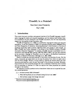
D. Processing units Currently available embedded systems require electrical energy to operate. For mobile systems, energy availability is a deciding factor. Figure 7 shows the energy efficiency of various hardware technologies. As a figure of merit, this diagram uses the number of operations that can be achieved per Joule. As a result of improvements in process technology, energy efficiency has improved over recent years. For a fixed process technology, energy efficiency is largest for application-specific integrated circuits (ASICs). Energy efficiency of field programmable gate arrays (FPGAs) has dramatically improved over time. Digital signal processors (DSP) are less efficient, but are softwareprogrammable. Standard microprocessors are even less efficient. For high-performance mobile applications, we need an energy efficiency corresponding to the upper right corner of the diagram, the “sweet spot”. However, energy efficiency and flexible programming are conflicting goals.
DAC.COM KNOWLEDGE CENTER ARTICLE www.dac.com
Page 11 of 21
1000
C
ASI 100
A
FPG
+
+ +
1
P
DS
+
U
MP
0.1
xc e
ll ooo oo o oo oo o ooo o o o oo oo o+o ++ + o + RISC +o+o oo o o o+ o o o o + o o o o o x cell ASIC + o MPU FPGA + RISC DSP
o
1990
0.001
2010
o
2000
o
0.01
1995
+o
2005
GOP/J
10
Figure 7: Hardware efficiency (© De Man and Philips).
1. Application-specific integrated circuits (ASICs) The design of ASICs is not covered in this article, as this subject will be covered well by other entries in the DAC Knowledge Center. 2. Processors Many embedded systems are equipped with low-end microprocessors. Several books describe such processors (e.g., [GNE+08]). For high-performance applications, application domain-specific processors (such as DSPs) and application-specific instruction set processors (ASIPs) can provide the required energy efficiency. Design tools for such processors exist, for example from Tensilica [Ten10]. 3. FPGAs In many cases, full-custom hardware chips (ASICs) are too expensive and software-based solutions are too slow or too energy-consuming. Reconfigurable logic provides a solution if algorithms can be efficiently implemented in custom hardware. It can be almost as fast as special-purpose hardware, but in contrast to special-purpose hardware, the performed function can be changed by using configuration data. Due to these properties, reconfigurable logic finds applications in the following areas:
Fast prototyping: It is frequently desirable to generate a prototype, which can be used for experimenting with a system that behaves “almost” like the final system. Low-volume applications: If the expected market volume is too small to justify the development of special purpose ASICs, reconfigurable logic can be the right hardware technology for applications,which cannot be implemented in software.
DAC.COM KNOWLEDGE CENTER ARTICLE www.dac.com
Page 12 of 21
4.
Communication The various components in an embedded system must be able to communicate. For communication in embedded systems, several special requirements exist: For all systems that need to met real-time constraints, communication times must also be guaranteed. Several low-cost solutions such as standard Ethernet fail to meet this requirement. Respecting real-time constraints is feasible with appropriate arbitration techniques for communication media. For example, time-division multiple-access (TDMA) is clearly superior to a pure priority-based arbitration in this respect. Efficiency of communication hardware is frequently an issue. For example, power may need to be distributed via the communication medium, since separate power supplies for each communicating station may be too expensive. Physical robustness plays a key role.
E. D/A-conversion In the case of analog output devices, digital information must first be converted by digital-toanalog (D/A) converters. A standard design uses weighted resistors to generate a current which is proportional to the digital number. This current is then turned into a proportional voltage by using an operational amplifier [Mar10a]. The sampling theorem provides information on the extent to which the original analog signals may be reconstructed if needed [OSB09].
F. Output Output devices of embedded/cyber-physical systems include displays and electro-mechanical devices. The latter are called actuators, if they have a direct impact on the environment. There are far too many different types of actuators to list all of them in this article.
G. Secure hardware The general requirements for embedded systems can often include security. If security is a major concern, special secure hardware may need to be developed. Security may need to be guaranteed for communication and for storage [KM06]. Also, security might demand special equipment for the generation of cryptographic keys. Special hardware security modules have been designed. One of the design goals for such modules is to resist side-channel attacks such as measurement of supply current or electromagnetic radiation. Such modules include special mechanisms for physical protection (shielding, or sensors to detect tampering with the modules). Special processors may support encryption and decryption. In addition to the physical security, we need logical security, typically using cryptographic methods. Smart cards are a special case of secure hardware that must run using a very small amount of energy. In general, it is necessary to distinguish between different levels of security and levels of knowledge of “adversaries”. A full presentation of the techniques for designing secure hardware is beyond the scope of this article. Interested readers are referred to Gebotys [Geb10] and the CHES workshop proceedings [CG09].
IV. STANDARD SOFTWARE A. Embedded operation systems
DAC.COM KNOWLEDGE CENTER ARTICLE www.dac.com
Page 13 of 21
Not all components of embedded systems need to be designed from scratch. Instead, there are standard components that can be reused. Standard software components that can be reused include system software components such as embedded operating systems (OS), real-time databases, and other forms of middleware. The last term denotes software that provides an intermediate layer between the OS and application software (including, for example, libraries for communication). Calls to standard software components may already need to be included in the specification. Therefore, information about the application programming interface (API) of these standard components may already be needed for completing executable specifications. Except for very simple systems, scheduling, task switching, and I/O require the support of an operating system suited for embedded applications. Task switch (or task “dispatch”) algorithms multiplex processors such that each task seems to have its own processor. Embedded operating systems should provide a high level of configurability in order to take the large variation of application requirements and hardware platform features into account.
B. Real-time operating systems Cyber-physical systems are usually real-time systems. Operating systems used in such systems must be real-time operating systems. Definition: (A) “real-time operating system is an operating system that supports the construction of realtime systems” [Tak01]. Real-time operating systems should have the following properties [Tak01]:
The timing behavior of the OS must be predictable. For each service of the OS, an upper bound on the execution time must be guaranteed. In practice, there are various levels of predictability. For example, there may be sets of OS service calls for which an upper bound is known and for which there is not a significant variation of the execution time. Calls like “get me the time of the day” may fall into this class. For other calls, there may be a huge variation. Calls like “get me 4MB of free memory” may fall into this second class. In particular, the scheduling policy of RTOS’s must be deterministic. There may also be times during which interrupts must be disabled to avoid interference between tasks (this is a very simple way of guaranteeing mutual exclusion on a mono-processor system). The periods during which interrupts are disabled must be quite short in order to avoid unpredictable delays in the processing of critical events. The OS must manage the scheduling of tasks. Scheduling can be defined as mapping from the set of tasks to intervals of execution time, including the mapping to start times as a special case. Also, the OS possibly has to be aware of task deadlines so that the OS can apply appropriate scheduling techniques (there are, however, cases in which scheduling is done completely off-line and the OS only needs to provide services to start tasks at specific times or priority levels). Some systems require the OS to manage time. This management is mandatory if internal processing is linked to an absolute time in the physical environment.
C. Middleware Any software in between the operating system and the application software is called middleware. Communication software may be the most important type of middleware. Such software supplements the communication features provided by the operating system. Example of such middleware include
DAC.COM KNOWLEDGE CENTER ARTICLE www.dac.com
Page 14 of 21
CORBA [Obj03]: CORBA extends object access in object-oriented programming to remote objects. As an alternative to CORBA, the message passing interface (MPI) [MHP10] can be used for communication between different processors. MPI is a very frequently used library, initially designed for high-performance computing. The POSIX thread (Pthread) library is an application programming interface (API) to threads at the operating system level [Bar10]. A set of threads can be run in the same address space. Therefore, communication can be based on shared memory communication. This avoids the memory copy operations typically required for MPI. The library is therefore appropriate for programming multi-core processors sharing the same address space. Other middleware software include OpenMP [Ope08], JXTA(TM) [JXT10] and UPnP [UPn10].
Many of the proposals for middleware have initially neglected real-time issues. As a result, the corresponding middleware can hardly be used for real-time systems. For use in real-time systems, several real-time extensions have been proposed (see, for example, [MPI01]).
V. EVALUATION AND VALIDATION A. Purpose and scope Specification, hardware platforms and system software provide us with the basic ingredients which we need for designing embedded systems. During the design process, we will have to validate and to evaluate designs rather frequently. Therefore, we will describe validation and evaluation before we talk about design steps. Validation and evaluation, even though different from each other, are very much linked (for example, since simulations are used for both). Definition: Validation is the process of checking whether or not a certain (possibly partial) design is appropriate for its purpose, meets all constraints, and will perform as expected. Definition: Validation with mathematical rigor is called (formal) verification. Validation is important for any design procedure, and hardly any system would work as expected, had it not been validated during the design process. Validation is extremely important for safetycritical embedded systems. Definition: Evaluation is the process of computing quantitative information of some key characteristics (or “objectives”) of a certain (possibly partial) design.
B. Multi-objective optimization Design evaluations will, in general, lead to a characterization of the design by several criteria (or “objectives”), such as average and worst-case execution time, energy consumption, code size, dependability and safety. The need to consider several objectives is actually one of the characteristics of embedded/cyber-physical systems. Merging all these objectives into a single objective function (e.g., by using a weighted average) is usually not advisable, as this would hide some of the essential characteristics of designs. Rather, it is advisable to return to the designer a set of designs among which the designer can then select an appropriate design.
DAC.COM KNOWLEDGE CENTER ARTICLE www.dac.com
Page 15 of 21
Such a set should, however, only contain “reasonable” designs. Finding such sets of designs is the purpose of multi-objective optimization techniques. In order to perform multi-objective optimization, we consider an m-dimensional space X of possible solutions of the optimization problem. These dimensions could, for example, reflect the number of processors, the sizes of memory, types and number of buses. For this space X, we define an n-dimensional function
f ( x) ( f1 ( x),..., f n ( x)) where x X which evaluates designs with respect to several criteria or objectives (e.g., cost and performance). Let F be the n-dimensional space of values of these objectives (the so-called objective space). Suppose that, for each of the objectives, some total order < and the corresponding ≤-order are defined. In the following, we assume that the goal is to minimize our objectives. Definition: Let S F be a subset of vectors in the objective space. V F is called a nondominated solution with respect to S if there does not exist any element w S such that w is not worse than v with respect to any objective and better than v with respect to at least one objective. Figure 8 (left) highlights the different areas in the objective space, relative to design point (1). O 2 (e.g. memory space) indifferent
O 2 (e.g. memory space)
dominated by (1) (inferior designs) (1)
min
dominated design points
+ min
+ +
dominating (1) indifferent
(superior designs) min
O 1 (e.g. energy)
+
min
O 1 (e.g. energy)
Figure 8: (a) Pareto point. (b) Pareto front. The upper right area corresponds to designs that would be dominated by design (1), since they would be “worse” with respect to both objectives. Designs in the lower left rectangle – if they exist – would dominate design (1), since they would be “better” with respect to both objectives. Designs in the upper left and the lower right areas are indifferent: they are “better” with respect to one objective and “worse” with respect to the other. Figure 8 shows a set of Pareto points, i.e., the so-called Pareto front. Design space exploration (DSE) based on Pareto points is the process of finding and returning a set of Pareto-optimal designs to the user, enabling the user to select the most appropriate design. The following list contains objectives relevant for embedded/cyber-physical systems: 1) 2) 3) 4)
Average performance: This objective has a dominating role for PC-like systems, but may be completely irrelevant in cyber-physical systems. Worst-case performance/real-time behavior: In contrast, the worst-case performance is a dominating objective for cyber-physical systems. Energy/power consumption: This objective is extremely important for mobile systems. Temperatures/thermal behavior: The thermal behavior needs to be considered for all systems converting a significant amount of electrical energy into thermal energy.
DAC.COM KNOWLEDGE CENTER ARTICLE www.dac.com
5)
6) 7) 8) 9)
Page 16 of 21
Reliability: Cyber-physical systems must be reliable. However, future silicon technologies are known to be more susceptible to transient faults. Therefore, reliability evaluation and techniques for improving reliability are becoming increasingly important. Electromagnetic compatibility: This objective is important in environments with are sensitive to electromagnetic radiation. Numeric precision: A minor loss in numerical precision can be tolerated in several applications. Accepting such a loss can improve the design in terms of other objectives. Testability: Costs for testing systems can be very large, sometimes larger even than production costs. Hence, testability should be considered as well, preferably already during the design. Cost, weight, robustness, usability, extendability, security, safety, environmental friendliness: These are additional objectives with may be important in some cases, but they are not universally taken into account.
C. Execution time Of all the objectives that need to be considered, we focus on the one which has a large impact on design decisions: In contrast to desktop computing, worst-case execution times (WCETs) need to be considered very carefully. Some definitions related to the WCET are shown in Figure 9. Distribution of execution times BCET
WCET t
BCET EST
WCET EST
Figure 9: WCET-related terms. The worst-case execution time is the largest execution time of a program for any input and any initial execution state. Unfortunately, the WCET is extremely difficult to compute. In general, it is undecidable whether or not the WCET is finite. This is obvious from the fact that it is undecidable whether or not a program terminates. Hence, the WCET can only be computed for certain programs/tasks. For example, for programs without recursion, without while loops and with loops having statically known iteration counts only, the WCET can be computed. But even with such restrictions, it is usually practically impossible to compute the WCET. The effect of modern processor architectures’ pipelines with their different kinds of hazards, and memory hierarchies with limited predictability of hit rates, is difficult to precisely predict at design time. Computing the WCET for systems containing caches, pipelines, interrupts and virtual memory is an even greater challenge. As a result, we have to be happy if we are able to compute good upper bounds on the WCET. Such upper bounds are usually called estimated worst-case execution times, or WCETEST. Such bounds should have at least two properties: 1) 2)
The bounds should be safe (WCETEST ≥ WCET). The bounds should be tight (WCETEST – WCET