The concept of the GOLLUM integrated navigation receiver and the chosen application speci c proces- sor (ASP) architecture are shown in gure 1. To sig-.
Embedded DSP Design for Integrated Radio Navigation A.A. Anteneh, R. Otten, L.K. Regenbogen
Delft University of Technology, Department of Electrical Engineering, Circuits and Systems Group, Mekelweg 4, 2628 CD Delft, The Netherlands tel +31 (0)15 278 28 45 fax. +31 (0)15 278 61 90 [anabo][otten][loekre]@cas.et.tudelft.nl
Abstract | Integrated navigation has been an estab- towards meeting the receiver goals mentioned earlier.
lished method to increase the reliability of navigation systems. Current integrated navigation approaches go further to a hybrid mode of operation in which the performance of individual navigation systems is enhanced. We discuss the design of a receiver for such integrated integrated navigation purposes. We focus on the baseband signal processing tasks for which an embedded processor is developed. By means of a case study, a DSP design for the Loran-C DSP, we show the customization of an application speci c processor. Keywords | Integrated Navigation, Embedded Systems, DSP, MOVE Processor.
Any similarities in the signal processing features of the individual subsystems are used to identify sharable hardware resources. In this paper, we focus on the baseband signal processing of the GOLLUM receiver. First, we introduce the concept behind the receiver design. Then, we present our approach to the partitioning of signal processing tasks into hardware (HW) and software (SW) components for the design of a cost e�ective application speci c processor. Finally, a case study is given which shows the functional HW/SW partitioning of the Loran-C DSP. A new dedicated FIR lter algorithm is also discussed which uses time-distributed computation to reduce the computational complexity of the direct-form FIR lter.
I. Introduction
In recent years, the navigation community has been busy investigating robust methods for reliable and accurate radio navigation. Individual navigation systems systems su�er either from inherent or deliberate accuracy limitations. Similarly, the everywhere and every time availability of individual systems is below what critical applications, such as air navigation, demand. The adopted solution to combat such shortcomings is integrated or hybrid navigation. Two or more systems are operated in such a way that information is shared among them to raise the performance of the combined system. One such approach to integrated radio navigation is GOLLUM [1]. The objective of GOLLUM is to develop a low-cost, low-power and low-weight navigation receiver which is suitable for di�erent navigation applications. To achieve this, it combines four complementary subsystems: GPS, Omega, Loran-C and MLS. Resource sharing is the major technique
II. The GOLLUM Integrated Navigation Receiver
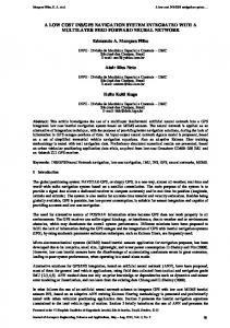
The concept of the GOLLUM integrated navigation receiver and the chosen application speci c processor (ASP) architecture are shown in gure 1. To signify the resource sharing potential, the receiver frontends (sensors) have been paired according to their frequency ranges. Components such as frequency synthesizers and A-to-D converters are candidates for hardware sharing. The baseband signal processing is shown in the shaded and light rectangle. Each of the subsystem has functionalities that are best mapped to hardware or software for a low-cost realization. The computationally complex tasks, such as ltering, carrier and clock synchronization, are likely to be mapped to hardware. Other functionalities such as data processing are implemented in software. In the following section, we 19
20
Proceedings of the ProRISC Workshop on Circuits, Systems and Signal Processing 1997 (5 GHz)
(1.2 GHz)
MLS SENSOR
GPS SENSOR
HW SW
MLS Sub-System
LORAN_C SENSOR (100 kHz)
General Purpose FUs
GPS Sub-System
NAVIGATION PROCESSOR LORAN-C Sub-System
To/From Memory
G1 Control Unit
OMEGA Sub-System
OMEGA SENSOR
G2
G3
Transport Unit A1 A2 A3 A4 Appl. Specific FUs
To/From Sensors
(10 kHz)
GOLLUM Concept
MOVE Architecture
Fig. 1. Concept of the Gollum Navigation receiver
show how the functional HW/SW partitioning can be performed using the facilities that come with the ASP. The MOVE architecture [2] has been chosen as the target architecture of the GOLLUM DSP. The architecture is suitable for embedded applications due to the ease of processor customization by varying the number of busses and the standard (general-purpose) functional units (GPFUs). In case the algorithm complexity exceeds the processor capacity, dedicated hardware modules are included as application speci c functional units (ASFUs). III. Functional HW/SW Partitioning
Hardware-software (HW/SW) partitioning of algorithms plays a key role in optimal embedded system design. Even though the software alternative provides better exibility and short design time (by using o�-the-shelf components), certain receiver algorithms such as clock and carrier synchronization may be too demanding for a programmable processor [3]. In such instances, developing applicationspeci c hardware modules become a necessity. Research on embedded systems design has focused on methods and tools for automatic HW/SW partitioning [4], [5], [6]. In [4], an algorithm is rst implemented in software and its execution speed analyzed on the chosen processor architecture. If the speed requirement is not met, parts of the algorithm are moved to dedicated hardware. In [5], the algorithm is rst implemented in hardware and then less critical parts are transferred to software. To address the issue of uncertainty in HW and SW costs, i.e., area and execution time, possibilistic methods are described in [6]. The MOVE ASP synthesis addresses the embedded
system design in much the same way as current HW/SW co-design systems. However, the communication overhead between the ASIC and the general purpose processor in HW/SW co-design is absent in the MOVE-based approach. The MOVE architecture comes with both hardware (processor) synthesis and software (code) generation tools [2], [7]. This synthesis framework provides a design space exploration facility which automatically analyzes algorithm performance over many possible MOVE realizations. The designer can then select one of the realizations which meets the execution time requirement at a minimal cost. The tools in the MOVE framework are capable of synthesizing processors for 32-bit (integer) or 64-bit ( oating point) data bus widths. Obviously, these limitations restrict the applicability of the synthesis tools. However, the synthesis results can still be used for design problems with smaller dynamic ranges as long as the designer makes sure to scale down the bus and register widths before the layout phase. The design space exploration, which gives the execution pro le of an algorithm for di�erent combinations of move buses and functional units gives the desired information for deciding whether a given algorithm should be realized in hardware (special purpose FU) or software (using general purpose FUs). The case study in the next section contains algorithms with di�erent execution rates, e.g., FIR ltering at 400 kHz and phase tracking at 1 kHz. We perform the design space exploration on the computationally complex algorithm, i.e., the FIR lter. Then, the remaining algorithms are evaluated on the chosen MOVE processor to determine their execution load and see if the total computational load doesn't exceed the processor capacity. Some algorithms, though they have a low repetition rate, might dominate the resource usage for the time they are active. Such algorithms should be spread over their repetition interval to reduce their load per unit of time in order to enable real-time handling of more critical tasks. Figure 2 shows a functional (coarse-grained) HW/SW partitioning strategy which we apply in the next section for the Loran-C DSP design. Receiver functions whose execution demands exceed the processor capacity are passed to a hardware synthesis tool. The decision to keep an algorithm in software or develop a dedicated hardware module is based on how busy the processor buses are and how long the algorithm takes
before its completion. Since a dedicated hardware module is free of hardware and execution overheads, it is a preferred solution over using a separate MOVE processor for every complex algorithm.
21
Cycle-ID Loop s(t) (100 kHz)
A/D
16
Notch Filter Bank
FIR Bandpass Filter
Spectrum Estimation fs = 400 kHz
M1
HW Algorithm SW
HW Synthesis (Synopsis) Layout (OCEAN)
Simulation ASFU N
Resource Usage
Processor Description M2
OK
Fig. 2. Functional HW/SW Partitioning IV. Case Study: Loran-C DSP Partitioning
Loran-C is a terrestrial radio navigation system which is used in air, marine and land applications. In recent years, people's interest has grown in using Loran-C for terrestrial navigation in the European continent. However, due to the many transmitting stations near the Loran-C band (90-100 kHz), the receiver design requires extra e�ort in combating interferers. The research community has been working on methods of e�cient interference identi cation and rejection [8], [9], [10]. In this section, we present an extension to this e�ort by describing a low-complexity FIR lter algorithm. We also show how the HW/SW partitioning technique discussed earlier can be applied to the customization of the MOVE processor according to the Loran-C requirements. The digital signal processing part of the Loran-C subsystem is shown in gure 3. Following the 16-bit Ato-D converter are the FIR and adaptive notch lters which are used to assist the front-end analog bandpass lter in the interference rejection. The spectrum estimation block is used to identify synchronous interferers and tune the notch lters accordingly. Finally, the ltered signal is fed to the algorithms which perform acquisition and tracking functions. The tracking loop tries to align local timers to the arrival time of signals from at least three Loran stations.
Channel-1 Channel-2 Channel-3
Embedded DSP Design for Integrated Radio Navigation
Phase-Tracking Loop Strong Signal Search Clock Generation ck1
ck2
ck3
Time-Difference Measurement
TD1 TD2
Fig. 3. Digital signal processing in a Loran-C Receiver
The di�erence in the time-of-arrival (TD) is later used by a navigation program to compute positions in latitudes and longitudes. While the spectrum estimation and ltering blocks are executed at 400 kHz rate, the tasks inside the dotted region are executed every 1 ms. A. Low-Complexity FIR Filter Algorithm Depending on the interference strength, up to 80 dB interference rejection might be required to keep the error in the position estimates within the 15 meter bound [8]. The combined analog front-end and digital FIR bandpass lters, centered at 100 kHz and with 20 kHz bandwidth, play the major role in the interference suppression. To avoid the pulse distortion when using a high-order analog bandpass lter, the ltering burden is shifted to the FIR lter. The front-end lter acts as an antialiasing lter. Through simulations, a 264 tap FIR lter has been found to provide up to 60 dB interference suppression in the bands outside the 80 to 120 kHz range [11]. When combined with the attenuation from a 3rd-order analog bandpass lter, the desired 80 dB suppression level is achieved. A direct-form FIR lter architecture is shown in gure 4 [12]. At a sampling rate of fs = 400 kHz, the lter can be implemented using a single multiplyaccumulate (MAC) unit clocked at 264 � fs = 105:6 MHz. In [1] a vector register-based FIR lter architecture is presented, which, in addition to the MAC unit, consists of two 16-bit shift-registers (one for the delayline the another for the lter coe�cients). Assuming a 24-transistor register cell, the cost of the 16-bit vector registers amounts to 264 � 16 � 24 = 101376 trans. for the delay-line and 132 � 16 � 24 = 50688 for the coe�cients (132 due to symmetry). The total transistor count exceeds those on the sea-of-gates (SOG) chip.
22
Proceedings of the ProRISC Workshop on Circuits, Systems and Signal Processing 1997 x(n) c0
T
T
c1
c2
c(n)
T c264
x(n) y(n)
y(n-2)
accu1
y(n-1)
T
Fig. 4. Direct form FIR lter architecture
The computational and area requirements of the FIR lter can be reduced by avoiding unnecessary computations. For the Loran-C position computation only a few samples per pulse are required. From each LoranC station, a group of eight amplitude and phase modulated pulses are received at a known group repetition interval (GRI). The pulses are separated by 1 ms, and only the front part of the pulses contains a clean set of samples that can be used for time-of-arrival measurement. The remaining part is usually corrupted by re ections from the ionosphere{the so called skywaves. A reduced-complexity Loran-C FIR architecture has been proposed in [11]. The basic idea is to perform computations necessary to the desired output moments only and distribute the lter computations over the sample collection interval. Up to 10 ltered samples from the front part of a Loran-C pulse su�ce for elaborate cycle identi cation techniques [13]. In simpler receivers, just three samples taken about the zero-crossing being tracked are su�cient; the two left and right samples are used to identify the cycle being tracked. Figure 5 shows the proposed FIR lter architecture. The need for a full-length delay line is avoided by allocating accumulators for each desired output moment. The accumulators are reset every 1 ms and deliver the ltered data after all the coe�cients have been used up. At each sample moment, the input signal (x(n)) is weighted by di�erent coe�cient values (c(n)) and added to the contents of the corresponding accumulators. Since the coe�cients for the three ltered outputs are shifted versions of one another, a coe�cient delay line can be used to keep the access to the coe�cient RAM to one per sample period. The multiply-accumulate operations are multiplexed on a single MAC unit. Since the data samples are weighted as they come, i.e., FIR computations are distributed in time, the number of operations per sample period is equal to the number of accumulators. Since only a few accumulators (at most 10) are needed, the load per sample period is much smaller than the direct form case, in which
accu0
T accu2
y(n)
Reset
Fig. 5. A new FIR lter architecture dedicated for Loran-C application
264 operations must be completed. The remaining processing power per sample interval can be used to implement the notch lters. The area requirement of the new approach can be approximated as follows: if the multiplier outputs are truncated to 16-bits, a 16-bit accumulator can be used for each output. For the case of 10 ltered outputs, twenty 16-bit registers are needed including the coef cient delay line. Assuming half the FIR coe�cients (due to symmetry) are also on-chip, the total FIR register size amounts to 132 + 20 = 152, which is about 38% of the direct form architecture. It can be noted that the need for the coe�cient delay line can be avoided since the access rate to the on-chip coe�cients is fast and a few computations per sample interval (2.5 �s) have to be performed. B. Functional HW/SW Partitioning In this section, we present the result of a functional (coarse-grained) HW/SW partitioning of the LoranC DSP. First, the receiver is divided into functions (tasks) based on the architecture shown in gure 3. The execution time, memory size and processor resource utilization of the algorithms were obtained using the MOVE software framework. The design space exploration was conducted for the reduced-complexity FIR lter algorithm{which is still computationally demanding. The execution-time versus cost output of the explorer is shown in gure 6. While the execution time in nano-sec represents the run time for 200 calls of the FIR algorithm, the cost in number of adders represents the total area taken up by the functional units and the move buses. The primary factor for the choice of a speci c MOVE con guration is the satisfaction of the FIR lter exe-
Embedded DSP Design for Integrated Radio Navigation
23
TABLE I
Resource Utilization of Loran-C algorithms Algorithm bus
SSS 1 SSS 2 CID ZCT
usage [%] bus-1 bus-2 88 73 97 78 96 78 98 86
FU usage [%] FU1 FU2 FU3 FU4 37 10 0 29 36 6 6 42 32 10 0 39 39 2 1 36
Fig. 6. Execution time versus cost graph for the low- approach as it can replace the hardware overheads, such as instruction fetch-decode, load-store and cache complexity FIR lter algorithm
units, with a relatively simpler control unit. This approach is left for further investigation. Having the SW approach excluded for the FIR and IIR ltering, we evaluate the performance of the remaining Loran-C algorithms on candidate move processors. Now our objective is to use the cheapest possible move processor, since there will be a number of dedicated functional units to be added later. For this reason, we chose a processor with two internal move buses and 8 register units (this is equivalent to the left most point in gure 6). Table I shows the resource usage of di�erent algorithms during their execution, where FU1 = load-store, FU2 = shift + logic + = multiply, FU4 =theaddition . Thecompare, rst twoFU3 algorithms constitute initial (coarse) signal acquisition process: SSS1 which averages samples taken every 1 ms over many group repetition intervals (GRIs), and SSS2 which performs a correlation test over 8 consecutive samples (spaced by 1 ms) to nd the location of a strong signal and identify the transmitting station. SS1 is repeated every tp = 1 ms until the averaging is complete, while the second one is conducted on a stored signal and imposes little real-time requirement. For each Loran-C channel (see gure 3), CycleIdentify (CID) and ZeroCrossTrack (ZCT) are executed on 3 adjacent samples (2.5 �s apart) and repeated every tp = 1 ms. The execution time and processor utilization factors of the algorithms are shown in II. The execution times are computed from the execution cycle count delivered by the MOVE simulator and the processor clock period Tc = 1=30�s, which was found to be achievable for a similar mini ? move in [14]. Since SSS2 can be executed o�-line, no percentage processor load is computed; say, if its execution is spread over 1 sec, the e�ective load is just 1.13 % of each 1 ms interval.
cution time requirement, i.e, all operations are completed within the 2.5 �s sample interval. We see from the plot that the processor with cost 89 meets this criterion, since 3.6e+05 ns/200 = 1.8 �s is less than Ts = 2:5�s. Though the 'cost-89' processor is the cheapest solution, the fact that other signal processing will also be conducted on the same hardware and the remaining 2.5-1.8 = 0.7 �s is far too small, we have to resort to a faster processor. The processor with cost 103 is our next candidate; it is the point at which the curve begins to atten. This processor happens to have 4 parallel 32-bit move buses and 24 integer registers. Since the external instruction bus is only 32-bits wide and each move instruction costs 16-bits, an on-chip cache is required to keep the 4 internal buses busy and achieve the displayed execution time (2.2e+05 ns). Per sampling interval (Ts = 2:5 �s), the execution time is 2.2e+05 ns/200 = 1.1 �s or 44% of Ts . A 2nd-order IIR notch lter was also simulated on the same processor, resulting in an execution time of 0.7 �s. The analyzed FIR lter has 3 accumulators only, i.e., we assumed the simplest case in which 3 samples per Loran pulse are su�cient for position calculation. Even though the combined FIR and IIR lter load meets the timing requirement, 1.7 �s � Ts , the remaining interval (0.8 �s) still doesn't seem su�cient for other tasks from the Loran-C and other subsystems of GOLLUM. As can be seen from the graph in gure 6, increasing the processor resources further doesn't increase the execution speed. Since it is likely that we need more than 3 outputs per Loran pulse and three to four adaptive notch lters, the software approach doesn't seem attractive. The alternative is a dedicated lter functional unit. The functional unit can have advantages over the software From the discussion so far, we notice that all but
24
Proceedings of the ProRISC Workshop on Circuits, Systems and Signal Processing 1997
TABLE II
Execution time and processor utilization
Algorithm code size execution available [kB] te [�s] tp [�s] SSS 1 0.696 16.4 1000 SSS 2 2.334 8876 * CID 0.635 48.8 1000 ZCT 2.674 39 1000
te =tp
[%] 1.6 * 4.9 3.9
the FIR-IIR lter algorithms can be implemented in software. The only requirement is that the tasks be spread over their repetition interval in order to free the processor to handle more critical tasks. Now that dedicated functional units are included in the design, there are interrupts which need to be serviced in real time. We see that the total load, excluding the interrupt service overheads is about 11.5%. The remaining processing power will be used for the spectrum estimation routine, which is needed to adapt the notch lters, and other signal and data processing tasks of GOLLUM. V. Conclusion
In this paper, we have presented an approach for the design of an application-speci c processor for integrated radio navigation. Integration, which provides performance improvement, is achieved by sharing a single MOVE-based embedded processor among four di�erent navigation subsystems. The processor consists of general-purpose (standard) and application speci c functional units. We have shown how a semi-automatic method can be successfully applied for functional HW/SW partitioning of the receiver DSP. The rst step is classi cation of the receiver functions according to their execution rates. This gives us a preliminary indication of which parts can possibly be implemented in hardware or software. Following the functional classi cation, we apply the software analysis tools that come with the MOVE-processor architecture for studying the execution time and memory requirements of each algorithm. The Loran-C DSP design has been presented as a case study to demonstrate the use of the partitioning techniques presented in the paper. Due to the resource constraint (chip size and number of pins) the MOVE processor was restricted to two internal buses which were kept busy by two move instructions fetched via a 32-bit external instruction bus. This minimal proces-
sor architecture was found su�cient for most LoranC algorithms. The FIR bandpass lter and the IIR notch lter biquads were the exceptions. The FIR lter, even after simplifying its load using the lowcomplexity algorithm, has still to be implemented in dedicated hardware. The advantage of using the lowcomplexity algorithm is that the multiply-accumulate unit can now be used for implementing digital adaptive notch lters which are also required for optimal interference rejection. References
[1] E. Aardoom and A. Nieuwland, \A Single Chip Integrated Navigation System," International Journal of Navigation, vol. 46, no. 1, pp. 95{104, 1993. [2] H. Corporaal, Transport Triggered Architectures, Design and Evaluation, Ph.D. thesis, Delft University of Technology, 1995. [3] A.A. Anteneh, \Design and Implementation of MLS Data Demodulation and Processing Unit," Tech. Rep. TWAIO96-03, Delft University of Technology, Circuits & Systems Group, 1996. [4] R. Ernst, J. Henkel, and T. Benner, \Hardware- Software Cosynthesis for Microcontrollers," IEEE Design and Test of Computers, pp. 64{75, Dec. 1993. [5] R.K. Gupta, C.N. Coelho Jr., and G. de Micheli, \Program Implementation Schemes for Hardware-Software Systems," Computing Practices, pp. 48{55, Jan. 1994. [6] I. Karkowski, Performance Driven Synthesis of Digital Systems, Ph.D. thesis, Delft University of Technology, 1995. [7] J. Hoogerbrugge, Code Generation for Transport Triggered Architectures, Ph.D. thesis, Delft University of Technology, Feb. 1996. [8] M. Beckmann, Carrier Wave Signals Interfering with Loran-C, Ph.D. thesis, Delft University of Technology, Circuits & Systems Group, 1992. [9] Y. Bian and D. Last, \High-e�ciency Loran-C Interference Spectrum Analysis by Synchronous Sampling," Wild Goose Association, 22nd Annual Tech. Symp., 1993. [10] A.K. Nieuwland, \An Optimal Detection Algorithm for Harmonic Interference Signals in Loran-C," NAVIGATION: Journal of The Institute of Navigation, vol. 40, no. 1, 1993. [11] A.A. Anteneh, \E�cient FIR Filter Architecture for Loran-C Intereference Rejection," To appear in The Proceedings of the International Loran Association, oct 1997. [12] L.R. Rabiner and B. Gold, Theory and Application of Digital Signal Processing, Prentice Hall, 1975. [13] A.K. Nieuwland, \An Improved Cycle Identi cation Algorithm," WGA: Proceedings of the 21st Annual Tech. Symposium, Aug. 1992. [14] P. Stravers, Embeded System Design, Ph.D. thesis, Delft University of Technology, 1994.