A frame is the smallest addressable segment of the configu- ration memory .... port interface to Boundary Scan, was approximately. 150Ã2,197 = 81,666 seconds ...
Embedded Processor Based Fault Injection and SEU Emulation for FPGAs Bradley Dutton, Mustafa Ali and Charles Stroud
John Sunwoo
Dept. of Electrical and Computer Engineering Auburn University, Alabama
Electronics and Telecommunications Research Institute Daejeon, Republic of Korea
Abstract—Two embedded processor based fault injection
the configuration memory. Shorts and opens in the interconnect network can be emulated along with almost any fault in the logic resources that can be controlled by configuration memory bits. When downloading the intended system configuration, the faults to be emulated can be injected in the configuration data just prior to the actual download process [1]. Alternatively, the intended configuration can be downloaded with subsequent partial reconfiguration used to inject and emulate the fault.
case studies are presented which are applicable to Field Programmable Gate Arrays (FPGAs) and FPGA cores in configurable System-on-Chip (SoC) implementations. The case studies include embedded hard core and soft core processors which manipulate configuration memory bits to emulate physical and transient faults in the FPGA core including shorts and opens in programmable interconnect and many different faults in logic resources. The emulated faults are used to evaluate fault detection capabilities of Built-In Self-Test (BIST) approaches, including fault identification capabilities of diagnostic procedures, and to evaluate the effect of Single Event Upsets (SEUs), including their detection and correction. Embedded processor based approaches provide significant improvement over previous fault injection techniques and, in turn, enable a more thorough analysis of BIST, diagnosis, and SEU mitigation.1 1. INTRODUCTION AND BACKGROUND There are a number of Field Programmable Gate Array (FPGA) applications that can make use of the presence of physical faults. These applications include Built-In SelfTest (BIST) of the FPGA itself [1], some fault-tolerant design techniques [2], and Single Event Upset (SEU) detection/correction techniques for FPGA configuration memories [3]. These applications target FPGA devices as well as FPGA cores in configurable System-on-Chip (SoC) implementations. Verification, analysis, and evaluation of these applications can be performed with the ability to inject or emulate physical faults in the FPGA. It is difficult to find actual faulty devices and their usefulness is limited due to the fixed nature of the fault [1]. Physical faults can be created by etching the packaged device and creating opens in routing resources that lie at the top level of interconnect metal for example, but once again the usefulness of these devices is limited. A more efficient approach is to manipulate the configuration memory bits to emulate physical faults in the device [4]. For example, a stuck-at fault in a look-up table (LUT) bit can be emulated by overwriting the particular configuration memory bit and setting it to the desired stuck-at fault value. SEUs on the other hand can be emulated by flipping the value of bits in 1
This work was sponsored by the National Security Agency under contract H98230-04-C-1177 and supported in part by the National Science Foundation Grant CNS-0708962.
One of the first FPGA applications to use fault injection emulation was hardware acceleration techniques for fault simulation [4]. However, the download time for fault injection detracted from the hardware acceleration to the extent that the manipulation of configuration bits was abandoned and replaced by fault emulation circuitry that was modeled and downloaded with the circuit to be simulated [5][6]. The overhead of the additional fault emulation circuitry and its associated routing was significant but acceptable in the case of fault simulation [7]. The additional circuitry and routing was not acceptable in the case of BIST approaches since the goal was to maximize the resources under test in any given configuration such that there are no remaining resources available to emulate faults. As a result, fault injection via configuration memory bit manipulation has been used extensively to debug, verify, and analyze development of BIST configurations and diagnostic procedures for FPGAs [1][8]. Similarly, analysis of the affects of SEUs [3] as well as SEU detection and correction in FPGA configuration memories [9] can use manipulation of configuration memory bits and has been shown to be effective in emulating 97% of the SEUs induced and observed in radiation chamber experiments [3]. In this paper, we present two case studies of embedded processors used to manipulate FPGA configuration memory bits for FPGA BIST and SEU detection/correction applications. The first case study uses a hard core embedded processor that has dedicated program and data memories with write access to the configuration memory of an FPGA core in a configurable SoC. In this case study, described in Section 2, the device is the Atmel AT9K series Field Programmable System Level Integrated Circuit (FPSLIC). The second case study uses a soft core embedded processor in an FPGA for manipulation of configuration memory bits via an internal configuration access port (ICAP). The soft core processor is downloaded with the application to be injected
with faults. In this case study, described in Section 3, the devices include Xilinx Virtex-4 and Virtex-5 FPGAs. Each case study includes an overview of the device architectures, description of the fault injection emulation technique, and experimental results of the actual implementation. The paper is summarized and concludes in Section 4. 2. HARD CORE PROCESSOR CASE STUDY The Atmel AT94K series configurable SoC consists of an FPGA core, various RAM cores, and an 8-bit Advanced Virtual RISC (AVR) microcontroller core as shown in Figure 1 [10]. Three types of memory resources include [10]: 1) many small 32×4-bit RAMs distributed throughout the FPGA core, 2) a 4-Kbyte to 16-Kbyte dual-port data RAM shared by AVR microcontroller and the FPGA core, and 3) a 20-Kbyte to 32-Kbyte program memory accessible only by the AVR microcontroller and used for storing machine code. The AVR core is an 8-bit RISC architecture with 32 general purpose registers including a number of peripherals like watchdog timer, UART, etc [10]. There are two 8-bit bi-directional general purpose I/O ports. An 8-bit bidirectional data bus between the FPGA and AVR (controlled by the AVR) provides communications between the two cores. Whenever 8-bit data is written to (or read from) the data bus by the AVR, a strobe signal to the FPGA core is generated on FPGAIOWE (or FPGAIORE) along with one of 16 decoded select lines to the FPGA. There are up to four external interrupts to the AVR along with 16 interrupts from the FPGA. =RAM
=PLB
FPGA core
=repeater read, write, 18 select lines 8 data 16 interrupts
Peripheral Units AVR Processor
16 address 16 address Data 8 data RAM 2 control
8 3 data cont
Program Memory
Fig. 1. AT94K series SoC architecture
The FPGA core is constructed as a symmetrical N×N array of programmable logic blocks (PLBs), where N=48 for the AT94K40 device (the largest AT94K series SoC) [10]. Each PLB contains two 3-input LUTs, a D flip-flop, and additional multiplexers/gates. Every PLB has dedicated diagonal (X) and orthogonal (Y) local routing resources to its neighboring PLBs, as shown in Figure 2a [10]. As shown in Figure 2b, the vertical and horizontal global routing resources associated with each PLB traverse a total of four PLBs (×4 lines) and eight PLBs (×8 lines). Vertical and horizontal bus repeaters are placed at the boundaries of every 4×4 array of PLBs (shown in Figure 2c for the horizontal bus) to prevent signal degradation in lengthy and/or
heavily loaded signal nets. The repeaters also facilitate connections between ×4 and ×8 lines as seen in Figure 2d. = Programmable Interconnect Point (PIP) X
Y
X
Y
PLB
Y
X
Y
X
PLB (a) local routing = ×4 line
= ×8 line
(b) global routing (1 PLB) =repeater
×4 line
×8 line 4 PLBs 8 PLBs (c) horizontal repeaters in global routing
d) repeater connections
Fig. 2. AT94K routing architecture
The AVR microcontroller core can write to (but not read from) the FPGA core configuration memory such that the FPGA can be dynamically reconfigured (either fully or partially) by the AVR core during normal system operation [10]. The FPGA configuration memory access is via a 24bit address bus and 8-bit data bus. The address bus is partitioned into three 8-bit components referred to as FPGAX, FPGAY, and FPGAZ. FPGAX and FPGAY correspond to horizontal and vertical location of the programmable resource in the array while FPGAZ corresponds to specific logic/routing resources within the specified programmable resource. A write to the 8-bit data bus, FPGAD, results in a write cycle to a byte of the FPGA configuration memory. Sets of BIST configurations were developed to test the various programmable resources in the FPGA core including PLBs, RAMs, and the programmable interconnect network with horizontal and vertical repeaters [11]. During the verification and analysis of the sets of BIST configurations, every configuration bit associated with the specified resource under test was injected in turn with a stuck-at-0 fault and a stuck-at-1 fault. For each fault injected, the BIST configurations that target that resource were applied (with the injected fault present). The BIST results indicate which BIST configurations, if any, detected the emulated fault. Because of the large number of faults to be emulated (twice the number of configuration bits) for each BIST configuration, injecting the faults in the configuration download file prior to each download takes considerable time as indicated by the “download run time” in Table I. Note that bank clock and set/reset lines are associated with the vertical repeaters, hence, the larger number of configuration bits when compared to the horizontal repeaters and associated routing.
TABLE I Embedded Fault Injection Run Time Analysis for AT94K40 Processor BIST Config Total Download Resource Bits Faults Run Time Run Time Configs PLB with 4 hr 4 min 8 81 162 flip-flops 29 min 34 sec Vertical 3 hr 4 min 20 71 142 Repeaters 55 min 1 sec Horizontal 3 hr 3 min 20 65 130 Repeaters 36 min 40 sec Free RAM 3 4 8 13 min 14 sec
BIST configurations can also be generated and executed by the embedded AVR processor [11]. In this case, fault injection emulation is somewhat more difficult since the processor core has write-only access to the FPGA configuration memory. If the processor core could also read the configuration memory, it could perform a read-modify-write (RMW) operation to inject a fault at any desired configuration memory bit. With write-only access, one must also know the normal BIST configuration data for each configuration memory byte in order to inject a single fault without disturbing the other seven bits of configuration data; otherwise, we could be injecting eight faults at a time. When the embedded processor is generating the BIST configuration, the information is contained within that resident program. As a result, the fault injection emulation can more realistically be performed from the embedded processor, although the development effort is greater without the RMW capability. Table I gives the run time when using the embedded processor core to perform fault injection emulation along with the BIST configuration generation and execution. A speed-up of almost a factor of 60 is obtained when the embedded processor core performs the fault injection emulation analysis including BIST configuration generation, BIST sequence execution, and BIST results retrieval. 3. SOFT CORE PROCESSOR CASE STUDY The configuration memories of Virtex-4 [12] and Virtex5 [13] FPGAs are partitioned into frames, where each frame has a fixed length of 1,312 bits, or forty-one 32-bit words. A frame is the smallest addressable segment of the configuration memory; therefore all memory write/read operations must be performed on whole frames. In Virtex-4 devices, a frame contains the configuration data for 16 rows of configurable logic blocks (CLBs) and input/output (I/O) tiles, or four rows of block random access memories (RAMs) and digital signal processors (DSPs) tiles in the same column [12]. In Virtex-5 devices, a frame covers 20 rows of CLBs and I/O tiles or five rows of block RAMs and DSPs tiles [13]. This means that individual FPGA resources cannot be reconfigured without also providing explicit configuration data for other FPGA resources that occupy the same frame. Virtex-4 and Virtex-5 FPGAs incorporate several configuration registers to provide write/read access to the configuration memory. The Frame Address Register (FAR) stores the memory address to/from which frame data is written/read. The Frame Data Register Input (FDRI) and Frame Data Register Output (FDRO) registers facilitate in-
put/output data to/from the configuration memory. There are other registers such as the status (STAT) register, the cyclic redundancy check (CRC) register, and the command (CMD) register which stores the next register operation to perform such as “Write FAR” or “Read FDR0”. To write/read to/from the configuration memory, a combination of these registers must be used. These registers are accessible from both Boundary Scan and SelectMAP configuration interfaces as well as the internal configuration access port (ICAP) located in, and accessible from, the FPGA fabric. Emulated SEUs, or faults injected for BIST, require the reconfiguration of a single configuration memory bit after system configuration, or each BIST configuration, is downloaded. Furthermore, the contents of the frame, which configure multiple rows of resources, must be preserved during reconfiguration for emulated SEU/fault injection. Our approach takes advantage of partial reconfiguration and read back capabilities of Virtex-4 and Virtex-5 FPGAs to implement RMW for bit-level partial reconfiguration. 3.1. Overview of Approach The basic approach begins with locating the frame containing the target bit for fault or SEU emulation. The frame is read in its entirety and stored. Next, the target bit is located within the frame, and overwritten with the desired stuck-at value in the case of a fault. This approach also supports emulation of SEUs by simply inverting the target bit. Finally, the modified frame is written back to the same location in the configuration memory from which it was read. Optionally, a subsequent read back of the frame can be used to verify the frame RMW results. The frame address and index of the bit targeted for fault/SEU emulation are stored in a list of faults/SEUs to be emulated. For each fault in the list, the BIST configuration is downloaded, executed with the fault on the device, and the results retrieved. If any of the output response analyzers (ORAs) record a failure, indicating a faulty block under test (BUT), the fault has been detected [9]. However, most tests of a specific FPGA resource require multiple BIST configurations to test its programmability and achieve high fault coverage. Given N BIST configurations and M faults in the fault list, the total number of downloads, executions, and retrievals of BIST results is N×M. The main reason why this many downloads are required is that there is no way to reset the ORAs once a fault is detected such that failures are latched until a new configuration is downloaded. Partial reconfiguration can be used to reduce download time, but it does not reset the ORAs between two consecutive BIST configurations. Therefore, once a fault is detected, the ORAs return failure indications for the remaining BIST configurations that may not detect the fault. Even though ORA failure indications imply a fault was detected, it is not clear which configuration detected the fault for proper evaluation and verification. Since the BIST approach pseudo-exhaustively tests multiple identically configured BUTs, the fault coverage in one
# Faults Detected
90 2500
Individual FC
80
2000
Cumulative FC
70 60
1500
50 40
1000
30 20
500
10 0
0 1
2
3 4 Configuration #
5
6
Fig. 3. SliceL Simulation Stuck-at Fault Coverage 100
600
90 500
80 70
400
60 50
300
40 200
30 20
100
10 0
0 1
2
3 4 Configuration #
5
6
Fig. 4. SliceL Fault Injection Stuck-at Fault Coverage 8000 7000
Readback Execution Configuration
6000 5000 4000 3000 2000 1000
SX
95 T
50 T SX
35 T SX
85 T
11 0T LX
LX
50 T LX
30 T LX
20 T
0 LX
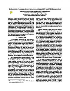
The biggest drawback of prior fault injection approaches is the large number (N×M) of downloads required to emulate a sufficient sample of configuration memory bit faults. To obtain the results shown in Figure 4, a total of 614×6 = 3,684 downloads, fault injections, BIST executions, and results retrievals were required. Additionally, any revision to a BIST configuration requires the complete fault list be run again to ensure that the modified configuration does not jeopardize fault detection capabilities. The total time required for fault injection can be calculated by multiplying the test time for the set of BIST configurations by the number of faults in the fault list. Figure 5 shows the total test time for the set of all CLB BIST configurations using compressed downloads via a 50MHz Boundary Scan interface. Consider the set of CLB BIST configurations for the midsized LX50T, which requires 3,147 ms using the 50 MHz Boundary Scan interface from Figure 5. For the complete list of 698 configuration memory bit faults (which includes SliceM mode configuration bits), the fault injection time is 698×3.147 = 2,197 seconds. The more realistic fault injection time that we experienced, using a 333 kHz PC parallel
100
3000
# Faults Detected
A total of 3,006 collapsed stuck-at faults were found for the SliceL and another 8,462 faults for SliceM, all of which were cumulatively detected in fault simulation. These comprehensive fault lists include all faults affecting the CLB, including configuration memory bit stuck-at faults. Therefore, by using fault injection to emulate a subset of the complete fault list (specifically, those faults affecting the configuration memory bits), both the quality of the BIST configurations and the accuracy of the gate-level fault simulation models can be gauged. Less than 100% fault coverage from fault injection would suggest inaccuracies in the simulation model and potentially lower fault coverage than the fault simulations suggest. Of the 3,006 faults in the SliceL, 614 represent configuration memory bit stuck-at faults. These faults were emulated using the RMW approach previously described, with results shown in Figure 4. Using fault injection, 100% of the configuration memory bit faults affecting the SliceL mode of operation were detected, confirming the simulation results in Figure 3. Furthermore, the similarity of the fault coverage trends in Figures 3 and 4 helps to verify the accuracy of simulation models.
port interface to Boundary Scan, was approximately 150×2,197 = 81,666 seconds, or 91.53 hours. This lengthy application time prompted us to develop the embedded soft core processor based fault injection approach which greatly improves the test time by both increasing the achievable configuration interface frequency and by increasing the configuration interface word size using the ICAP.
Time (ms)
BUT may be assumed to be the overall fault coverage for all BUTs. This assumption greatly reduces the number of faults, M, that need to be emulated to obtain accurate fault coverage. For example, consider Figure 3, which shows the simulated individual and cumulative single stuck-at fault coverage for our BIST configurations for Virtex-5 CLBs in SliceL mode of operation. The simulation results are based on gate-level models of the CLB. The simulation results show that six BIST configurations are required to cumulatively detect 100% of single stuck-at faults in the CLB in SliceL mode of operation. However, as discussed in [14], the SliceL configurations must be applied twice such that every CLB serves both as a BUT and an ORA.
Fig. 5. Total CLB Test Time via Boundary Scan
The ICAP provides access to configuration registers and the configuration memory internally from the FPGA fabric. The ICAP works like the external SelectMAP interface except that it has separate 32-bit write and read buses, as op-
posed to a bidirectional 32-bit bus. The maximum operating frequency of the ICAP is 100 MHz, and it supports 8-bit, 16-bit, and 32-bit word sizes [12][13]. Every device includes two ICAPs; however, both ports can not be used simultaneously. A configuration bit in the configuration interface control register selects between the upper and lower ICAPs. The basic idea of an embedded fault/SEU emulation approach is to embed all of the logic required for frame RMW operations in the FPGA with the BIST or SEU controller configuration, using the ICAP to access the configuration memory. The benefit of embedded fault/SEU emulation approach is a minimum 32 times speed up over the external Boundary Scan configuration interface operating at the same frequency. In addition, configuration frequencies of 100 MHz are achievable within the FPGA fabric. 3.2. Architecture and Operation In our embedded fault/SEU emulation approach, a configuration containing both the BIST and SEU controller architecture and some additional logic is downloaded to the device. A list of fault/SEU sites (configuration memory address and bit indexes) is loaded into the embedded fault/SEU emulation logic in the FPGA either with the download or via an external interface after download. The embedded system proceeds by reading the configuration frame containing the first fault/SEU site. The frame is temporarily stored in the FPGA fabric while the target bit is located and the fault/SEU injected. Next, the frame is written back into the configuration memory and the BIST is allowed to execute as normal. When the BIST has run to completion, a single-bit pass/fail result for the configuration is stored. Normally, using the external interface, the BIST would proceed to the next configuration. However, the embedded logic can correct the previously injected fault, reset the ORAs, and then inject the next fault in the fault list, as can be seen in the flowchart in Figure 6. This approach has been implemented in Virtex-4 and Virtex-5 FPGAs. The implementation is discussed in the remainder of this section. Fault List
Start
IDLE
Read Frame Reset Fault List Pointer
Modify Bit
Write Frame
EOF ?
No Pause? No
Yes
to temporarily store frames during the RMW procedure. To accomplish the RMW, the B port is configured for 32-bit reads/writes and the B port input data bus is connected directly to the ICAP 32-bit data output bus. The B port data output bus is connected to the ICAP inputs via a 32-bit 2-to1 multiplexor. A frame read is initiated at the configuration memory frame address specified by the current fault and as the frame is read it is stored in the first forty-one 32-bit words in the block RAM. Next, the A port, configured for 1-bit read/write operations, is used to locate the target bit in the location specified by the fault list entry. In the case of a stuck-at 1/stuck-at 0 fault, a 1/0 is written at the specified bit. However, for SEU emulation, the contents of the specified bit address are read, inverted, and then written back to the same address. Finally, the modified frame is written back to the same address from which it was read via the 32bit B port output data bus. The fault list is stored in a second dual-port 18-kbit block RAM. The block RAM is configured with independent 512×36-bit read and write ports. The write port is connected to a Boundary Scan user access register with some additional logic for controlling the address bus; namely, a 32-bit shift register and address counter. The read port output bus of the block RAM is connected to the embedded fault/SEU injection logic and state machine. This block RAM structure allows a fault list to be written into the block RAM after the device is configured, and the list is immediately accessible by the fault/SEU injection logic and statemachine. However, the block RAM contents can also be initialized with a fault list in the VHDL model, eliminating the need to shift in the fault list via the Boundary Scan user access register. The block RAM is capable of storing up to 512 faults. The core must be capable of facilitating any length fault list up to the maximum of 512 faults. Therefore, an end-offile delimiter is required. Each 32-bit word in the block RAM has four parity bits which we use to store the file delimiters as well as control bits for stuck-at faults and bitflips (SEU emulation). The ability to inject multiple faults simultaneously is also desirable. This requires the inclusion of a ‘pause’ delimiter in addition to the ‘end-of-file’ delimiter. Our solution is to use the two least significant bits of the parity word to encode the fault type (stuck-at 1, stuck-at 0, or bit-flip) and to use the two most significant parity bits to store delimiters. The encoding scheme for these bits is shown in Table II, and the overall fault list format for the 32-bit data word and 4-bit parity word is shown in Table III.
Yes
Fig. 6. Frame Read-Modify-Write Flowchart
The embedded fault/SEU emulation core is entirely implemented in CLBs and two block RAMs in the FPGA fabric. A central component of the architecture is the dual port 18-kbit block RAM. Block RAMs have two independently configurable read and write ports (A port and B port); only the stored data is shared [12][13]. One block RAM is used
TABLE II. Parity Bit Encoding, where X = Don’t Care Parity[3:2] Description Parity[1:0] Description 00 Continue to next fault 00 Stuck-at zero 01 Pause at fault 01 Stuck-at one 1X End-of-file (EOF) 1X Bit-flip (SEU)
35:34 Delimiters
TABLE III. Embedded Fault List Format 33:32 32:21 20:0 Fault Code Bit Index Frame Address
The other significant component of the architecture is a 40×256-bit ROM implemented in LUTs in the FPGA fabric. This ROM is used to store all 32-bit ICAP instructions required for the frame RMW process. Another eight control bits control the ICAP write and clock enable inputs, and serve as inputs to the state machine logic. Instructions are stored in the ROM in the order in which they are written to the block RAM such that the block RAM may be sequentially addressed to initiate new frame reads and writes. The two block RAMs, instruction ROM, and ICAP are connected by an assortment of glue logic, including the large 32-bit 2-to-1 multiplexor. A block diagram of the overall embedded fault/SEU injection core appears in Figure 7. EOF PAUSED I C A P
VHDL Generic: Device Name GO
BSCAN
FaultList Block RAM
ROM & FSM
injection core block RAMs must be constrained to an area of the device away from the BIST configuration. Furthermore, the fault list must not contain the address of fault sites located in the embedded fault/SEU emulation core’s block RAMs. If any configuration memory frame addresses in the fault list happen to correspond with any of the embedded core’s resources, the core could overwrite a bit controlling the functionality of its own resources, resulting in likely failure. An example of a properly constrained design is shown in Figure 8. In the figure, a partial array of test pattern generators ORAs and CLBs under test is placed in the left half of the device with the embedded fault injection core is constrained to the right half of the device. The embedded fault injection core is loaded with fault addresses residing only in the left half of the array.
Frame RMW Block RAM
Fig. 7. Block Diagram of Fault Injection Core
3.3. Implementation Results The total number of slices used in Virtex-4 and Virtex-5 FPGAs is shown in Table IV. The primary reason for the difference in the number of logic slices is due to the fact that Virtex-5 incorporates four 6-input LUTs and four flip-flops per slice while Virtex-4 slices incorporate only two 4-input LUTs and two flip-flops. As a result, a Virtex-5 slice has twice the logic of a Virtex-4 slice – hence, Virtex-4 requires at least twice the number of slices. The smaller LUTs in Virtex-4 account for the additional slices. TABLE IV. Embedded Fault Injection Core Resources Attribute Virtex-4 Virtex-5 # lines of VHDL ~950 ~950 # block RAMs 2 2 # slices 228 67
The entire embedded fault/SEU emulation core is modeled in VHDL. For VHDL-based designs to be faulted, the fault/SEU emulation core may be instantiated in the top level of the design and synthesized with the intended system function to be faulted. Our BIST configurations are not modeled in VHDL, and in this case the fault injection core is added later in the design flow. Because our BIST configurations are modeled in Xilinx Design Language (XDL), the fault/SEU emulation core is synthesized and converted to XDL. The XDL of the embedded core and the BIST can then be combined and the design flow continued. In either case, it will be necessary to constrain the placement of the design to an area of the FPGA not targeted for fault injection. For example, if the fault injection core is embedded with a block RAM BIST configuration [15], the two fault
Fig. 8. Embedded Fault Inject Core (Right) with Half-Array of CLB BIST (Left) in Virtex-5 LX20T
The component declaration for the embedded fault/SEU injection core is shown in Figure 9. There are two primary inputs and two primary outputs for the model, as well as a generic which specifies the device. It should be noted that the Boundary Scan access to the fault list block RAM is embedded in the VHDL model, so these I/O do not appear in the top level component declaration. While the top level component declaration is identical for Virtex-4 and Virtex5, we maintain separate VHDL models for Virtex-4 and Virtex-5 because of some minor architectural differences between the device families. First, before writing to the configuration memory, a device ID check must be performed by writing the correct device ID to the IDCODE register. (This prevents accidental configuration with a bitstream formatted for another device.) The device IDs are kept in a LUT specific to Virtex-4 or Virtex-5 and are synthesized with the design as a constant; all Virtex-4 and Virtex-5 devices are supported. The generic device in the top level model is used to locate the correct device ID in the VHDL LUT. Second, the frame address register is formatted differently for Virtex-4 and Virtex-5, requiring small changes in the ordering of the fault list block RAM data
output bus. Finally, the input/output ordering for the ICAP in Virtex-5 is byte-swapped, compared to Virtex-4 ICAP. component fltinject is generic(DEVICE : string(1 to 6):="LX110T"); port( GO : in std_logic; CLK : in std_logic; EOF : out std_logic; PAUSED : out std_logic); end component fltinject; Fig. 9. Fault Inject Core Component Declaration TABLE V. Fault/SEU Injection Core I/O Descriptions Name Direction Description CLK Input Clock input up to 100MHz (ICAP max) Digital 1-shot input asserted to start injection of 1 or GO Input more faults separated by ‘pause’ delimiters. Asserted to indicate injection of 1 or more faults PAUSED Output separated by ‘pause’ delimiters is complete. EOF Output End-of-file asserted when end of fault list is reached.
The details of the primary inputs and outputs of the embedded core are summarized in Table V. The normal embedded fault injection process with a free running system clock (up to 100 MHz) is as follows: 1. Download BIST configuration with embedded fault injection core. (Optionally load fault list via Boundary Scan user access register.) 2. Toggle the GO input. Fault injection begins and runs to completion or until a “pause at fault” is encountered. 3. Monitor the PAUSED and EOF outputs. When PAUSED is asserted, execute the BIST configuration and record results. Repeat steps 2 and 3 until both PAUSED and EOF are asserted, then go to step 4. 4. Execute the BIST for a final time and record results. The end of fault file is reached and fault injection is complete. The embedded fault injection core has been verified on Virtex-4 and Virtex-5 devices. The core was initially verified by synthesizing only the core, loading a fault list, and executing the fault injection. To verify the injection of faults and bit-flips, the contents of the configuration memory were read back via the Boundary Scan interface and compared line-by-line to the original configuration download file. The core is capable of injecting stuck-at faults and SEU bit-flips anywhere in the configuration memory except block RAM contents. It is possible, however, to modify the architecture to support injection of faults in block RAM contents. Transient faults can be emulated by back-to-back SEU bit-flips such that the fault exists for a minimum of 3 µs - the minimum RMW time for a single frame. By incorporating two back-to-back bit-flips with a ‘pause’ delimiter, the user can control a transient fault for longer periods. 4. SUMMARY AND CONCLUSIONS We have presented case studies for two embedded processor approaches for SEU and fault injection emulation in FPGA and FPGA cores in reconfigurable SoCs. In the first case, a dedicated hard core processor was used to inject emulated faults in the FPGA core configuration memory via a write-only interface. The lack of read access to the con-
figuration memory increased the development effort and difficulty for use in the evaluation and analysis of BIST configurations for the FPGA. In the second case, a soft core processor was developed which was capable of readmodify-write access to the FPGA configuration memory. This facilitates the emulation of single and multiple stuck-at faults as well as bit-flipping for emulation of single and multiple SEUs. Hence, the embedded SEU/fault emulation processor supports a wide variety of fault types with no download penalty for more efficient and thorough evaluation of BIST and SEU mitigation. It should be noted that the fault injection is used in a fault-free device to analyze SEU detection/correction and BIST development and is not part of the manufacturing or system-level operation or test. REFERENCES [1] C. Stroud, J. Nall, M. Lashinsky and M. Abramovici, “BISTBased Diagnosis of FPGA Interconnect,” Proc. IEEE Int. Test Conf., pp. 618-627, 2002. [2] F. Kastensmidt, L. Carro and R. Reis, Fault-Tolerance Techniques for SRAM-based FPGAs, Springer, 2006. [3] E. Johnson, M. Caffrey, P. Graham, N. Rollins and M. Wirthlin, “Accelerator Validation of an FPGA SEU Simulator,” IEEE Trans. on Nuclear Sci., vol. 50, no. 6, pp. 2147-2157, 2003. [4] P. Ellervee, J. Raik, K. Tammemäe and R. Ubar, “Environment for FPGA-based Fault Emulation,” Proc. Estonian Acad. Sci. Eng., vol. 12, pp. 323–335, 2006. [5] S. Hwang, J. Hong and C. Wu, “Sequential Circuit Fault Simulation Using Logic Emulation,” IEEE Trans. on CAD of ICs and Systems, vol. 17, no. 8, pp. 724-736, 1998. [6] P. Civera, L. Macchiarulo, M. Rebaudengo, M. Reorda and M. Violante, “An FPGA-Based Approach for Speeding-Up Fault Injection Campaigns on Safety-Critical Circuits,” J. of Electronic Testing: Theory and Applications, vol. 18, pp, 261–271, 2002. [7] R. Sedaghat, “Routability estimation of FPGA-based fault injection,” Electronics Letters, vol. 41, no. 14, pp. 790-792, 2005. [8] T. Slaughter, C. Stroud, J. Emmert and B. Skaggs, “Fault Injection Emulation for Field Programmable Gate Arrays,” Proc. Int. Society for Optical Eng., vol. 4525, pp. 1-9, 2001. [9] B. Dutton and C. Stroud, “Single Event Upset Detection and Correction in Virtex-4 and Virtex-5 FPGAs,” Proc. ISCA Int. Conf. on Computers and Their Applications, pp. 57-62, 2009. [10] AT94K Series Field Programmable System Level Integrated Circuit, Datasheet, Atmel Corp., 2001.2 [11] J. Sunwoo and C. Stroud, “Built-In Self-Test of Configurable Cores in SoCs Using Embedded Processor Dynamic Reconfiguration,” Proc. Int. SoC Design Conf., pp. 174-177, 2005. [12] Virtex-4 FPGA Configuration Guide, UG071 (v1.5), Xilinx Inc., 2007.3 [13] Virtex-5 FPGA Configuration User Guide, UG191 (v2.7), Xilinx Inc., 2008.3 [14] B. Dutton and C. Stroud, “Built-In Self-Test of Configurable Logic Blocks in Virtex-5 FPGAs,” Proc. IEEE Southeastern Symp. on System Theory, pp. 235-249, 2009. [15] B. Garrison, D. Milton, and C. Stroud, “Built-In Self-Test for Memory Resources in Virtex-4 FPGAs,” Proc. ISCA Int. Conf. on Computers and Their Applications, pp. 63-68, 2009. 2 3
Available at www.atmel.com Available at www.xilinx.com