This paper presents a new approach to building software for embedded systems, based on the use of components in combination with contracts. The contracts ...
EMBEDDED SOFTWARE DEVELOPMENT: COMPONENTS AND CONTRACTS David URTING, Stefan VAN BAELEN, Tom HOLVOET and Yolande BERBERS {David.Urting, Stefan.VanBaelen, Tom.Holvoet, Yolande.Berbers}@cs.kuleuven.ac.be KULeuven, Department of Computer Science Celestijnenlaan 200A, B-3001 LEUVEN Belgium
ABSTRACT This paper presents a new approach to building software for embedded systems, based on the use of components in combination with contracts. The contracts specify the non-functional (resource) requirements of the different components in the system. This is especially important in embedded systems, since these systems are resourceconstrained. Our approach includes tool support for building embedded software and runtime support using a component system. The tool enables the construction of applications by connecting components and associating contracts to them. The runtime component system is responsible for contract management.
KEY WORDS: CASE Tools, Real-time, Embedded 1. INTRODUCTION When constructing software for embedded systems one has to consider aspects that do not appear in general software development. Embedded software often has to deal with memory constraints, tasks with critical timing demands, robustness demands, … Of course, gradations exist in the requirements of these systems, but in general the ability to deal with limited resources is one of the major challenges of an embedded software developer. As a result, embedded software is often built with these non-functional constraints taken into consideration, but no or little attention is given to code reusability. Also, embedded systems are becoming complex, and as a consequence the ad hoc design of these systems is time consuming and error-prone. Therefore, it is important to reuse software, but this reused software has to adhere to some important criteria. To solve the problem of reusability we use a component-oriented approach. A component can only be used in an embedded system if it does not break the working of the system and its available resources. A component that demands excessive resources cannot be
(re)used in a resource-constrained system, even if it provides the desired functionality. It is essential to know beforehand what the impact will be on a system when reusing a specific component. This can only be achieved if these non-functional aspects are specified as well. When a component has been found satisfactory, it can be inserted in the system. Even then, it is necessary to ensure the correct working of the component in respect to resource requirements imposed on it, either by the system or by other components. To make this possible we use a contract-based approach. A contract specifies an agreement on the resource consumption and has to be adhered to at runtime. The mechanism to monitor these contracts is being implemented in the runtime system (Component System). The method presented in this paper is supported by a tool (Composer Tool). The composer tool enables the construction of component and contract-based applications. The next section describes an example case, used to illustrate our ideas. It is followed by our definition of a component. In section four we describe the modeling of the example case using a component and contract-based approach. Section five discusses related work. Section six discusses the current status of the tool. We conclude in section seven. The work described in this paper is being performed in the scope of the SEESCOA project (Software Engineering for Embedded Systems, using a Component Oriented Approach), funded by the Belgian IWT.
2. SUPPORTING CASE To express our concepts and ideas we use an example application: a car regulator (or cruise control) system. The case has been defined for the SIVOES’2001 ECOOP workshop.
The case consists of a car regulator that applies a specific formula (based on the car’s current speed and the requested speed) to compute a value δC. This δC is fed to the engine unit, that in turn indicates if the car should go faster or slow down. The regulator has three states it can be in: ON, STDY (standby) or OFF. The regulator has also a screen display showing its state. To read the current speed, the car regulator uses a speedometer. The speedometer has a speed display, showing the car speed to the car driver. There are also some (time) constraints: � δC computation is done at 2Hz � speed measurement is done at 2 Hz � speed is displayed at 2Hz � when brakes are hit: regulator in OFF state within 500 ms � when regulator is switched off: regulator in OFF state within 500 ms � when engine is stopped: regulator in OFF state within 100 ms � when speed drops below 30 Mph: regulator in OFF state within 100ms � when the accelerator is hit: regulator in STDY state within 200ms � when the accelerator is released: regulator back to ON state within 250ms In the next sections we use this case to explain our modeling method (the SEESCOA method). But first the definition of a SEESCOA component is given.
3. COMPONENT DEFINITION Different component models are proposed in literature (like in [1]). Besides the advantage of multiple aspects being covered by the different approaches, this results in the disadvantage that terms or “buzz words” are too much overloaded (e.g. the terms “component”, “architecture”, “component system”). In this section we define our view on components.
many ports of this type the component has. Multiplicity is an important factor since a port can only be connected once to a connector. E.g. a multiplicity of “5” indicates that only five connectors can be attached to this port type. Messages are named and can contain parameters. The name and parameter list of a message is the signature of the message. Messages do not have a return value since communication is done asynchronously. Message signatures are only one part of the interface of a port. In fact, a component interface is defined on four levels: � � �
�
Syntactic level Description of the message signatures (name and parameters). Semantic level Description of pre- and postconditions. Synchronization level Description of the sequence of messages, loops and alternative paths. This level is described by means of Timed MSC’s. A Timed MSC is a Message Sequence Chart extended with notations for timing, loops and alternative paths. QoS level Specifies the component’s resource needs and consumption.
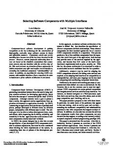
In this paper we focus on the first and third level. The fourth level is shortly elaborated in subsection 3.2. Figure 1 illustrates the definition. It shows two components from the case: a speedometer and a speed display component. The speed display is connected to the speed readout port of the speedometer using its speed reader port. Note the multiplicity of the speed readout port: an unspecified number of components can read the speed measured by the speedometer.
3.1 SEESCOA COMPONENT A (SEESCOA) component is a runtime object offering a coherent behavior. Some other component can access this behavior by sending asynchronously messages to the component. To do so, both components need a port. These ports have to be connected by a connector. Also, these ports have to understand each other: they have to speak the same protocol. The port protocol is described in the type or interface of the port.
3.2 QOS SPECIFICATION
Moreover, ports have a role and multiplicity: the role indicates the role the ports play in communication with other components and the multiplicity indicates how
The interface’s QoS definition level is the most challenging and also the most difficult to specify: it is not straightforward to describe QoS information in a general
Figure 1: component, port and connector
way without knowing the specific environment the component will be used in.
applied to the speed regulator case. We defined two types of models:
There is no single solution to this problem. Nevertheless three approaches can be used to give at least some idea on the QoS: �
�
�
QoS parameters can be measured against a reference setting: one hardware configuration, one OS configuration and one application type are chosen and then the component is tested in this setting. A formal calculation of the QoS can be performed. But for this to work, one has to know the dependencies between hardware, OS, etc. Also, one must be able to model these dependencies to create a function that in turn calculates the QoS parameters. This approach is very difficult and is not investigated in our research. Execution and measuring. This seems to be a valuable and achievable approach. The idea is that a component can be tested on the target platform before it is used. This testing produces measurements that can give an idea of the delivered QoS of the component.
The approach to specify the quality of service of a component is often a mixture of all techniques presented above. We currently use the last approach: execution and measuring.
4. COMPONENT AND BASED MODELING
CONTRACT-
This section shows the SEESCOA modeling method
� �
Instance models Scenario models
Both models use the basic concepts presented in section 3. Scenario models additionally use contracts. A contract specifies a non-functional requirement of the application. Currently, we use contracts to describe timing requirements. In section 4.2, a concrete example of such a timing contract is given.
4.1 INSTANCE MODELS An instance model is a view on a part of the complete application: it shows components and the connectors between them. All components in an instance model have a common goal: they perform one functional part of the complete application. In the regulator case one can define three instance models: the speedometer instance model, the regulator instance model and the integration instance model. The integration instance model integrates the first two models. In this paper only the speedometer and the regulator instance models are discussed.
4.1.1 SPEEDOMETER INSTANCE MODEL Figure 2 shows the speedometer instance model. It consists of a speedometer component (measuring the speed), a clock that pulses at 2 Hz and a speed display
Figure 2: instance model of the speedometer
Figure 3: instance model of the car regulator component. The speedometer component has a speed update multi-port: several other components can use this port to read out speed. The synchronization specification of each port is given using an MSC. The black vertical bar on the MSC indicates an activation: it represents the processing of the message. This enables us to define three time points (or hooks): when the message is sent, when it arrives and after it has been processed.
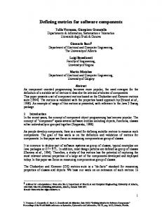
4.1.2 REGULATOR INSTANCE MODEL Figure 3 shows the regulator instance model. It consists of a regulator component (continuously calculating δC), a regulator controller and four monitors. Every monitor has a particular function (e.g. the speed monitor monitors the speed; if it drops below 30 Mph an OFF message is sent to the controller). The regulator controller combines (possible) multiple events from the monitors and sends out ON, STDY or OFF to the regulator using the regulator control port. The synchronization interface of the regulator control port is shown on the left: first the controller has to send an ON message, followed by zero or more STDY messages and finally the sequence is ended by sending an OFF message. This MSC is used in one of the scenario models described next.
4.2 SCENARIO MODELS A scenario model describes a particular non-functional requirement of the application. It shows all components
involved in the requirement and all contracts needed to describe the requirement. A scenario model has a specification purpose: it shows the requirements in a formal way. The scenario model is also used by the model compiler (which is a part of the tool): contracts are compiled to code. As such, these contracts can be monitored and violations can be logged, reported or even caught by the involved components. In this paper the TwoPartyTimingContract (also called a TPTC) and two special subtypes of this TPTC are shown. A TPTC has following attributes: � Start hook: validity of the contract starts when this hook occurs, � End hook: validity of the contract ends when this hook occurs. A TPTC has two specific subtypes: a PeriodTPTC and a DurationTPTC. A PeriodTPTC consists of: � Periodic hook: the hook that should occur periodically, � Period: a value indicating the period length. Finally, a DurationTPTC is specified by: � WCD: the worst-case duration between the occurrence of the end hook and the occurrence of the start hook. As such, these contract types can be used to describe and monitor timing constraints on the interaction between
Figure 4: speed display scenario model components. The two contracts are illustrated in the next two examples: the speed display scenario model and the regulator off actuation scenario model
4.2.1 SPEED DISPLAY SCENARIO In figure 4, two contracts are shown. This scenario model defines the constraint “The speed display has to update at 2 Hz”. This constraint is shown in contract C2: it indicates that when the start message has been sent, the update message has to be processed periodically. This
contract lasts until a stop message is received. Contract C1 can be seen as a “helper” contract: the speedometer component needs to receive ticks at 2 Hz if it wants to ensure contract C2. This is similar to the real world situation where a supplier offering a service depends on other suppliers.
4.2.2 REGULATOR OFF SCENARIO Figure 5 shows the contract C1, which defines the
Figure 5: regulator off scenario model
following constraint: “When the car driver hits the off button, the regulator has to shut down in 500 msec”. C1 is a contract between two implicitly connected components. The contract is hooked on the sending of the OFF message by the regulator on/off component and the end of the activation of the OFF message received by the regulator component.
contracts. These contracts have a specification and a runtime meaning: they are used to annotate timings at design time, and to monitor these timings at runtime. This runtime monitoring of contracts is valuable if one wants to detect non-functional failures at runtime. Of course, this contract-based method does not prove the correctness of the application. This requires the use of static verification methods.
5. RELATED WORK
This paper also gives our definition of an (embedded) component. The interfaces of such a component are specified on four levels. This strict specification is necessary if one wants to safely reuse components. Nevertheless, to make reusable components there is also the need for a good component-based methodology, but this lies outside the scope of the paper.
Some concepts in this paper are inspired by UML for Real-Time, more specifically on ROOM (see [2]). Ports, Connectors, Components, … are also present in the ROOM notation and methodology, although named differently. The contract-based approach is based on work done by Meyer [3]. The use of a four-level interface description is described in [4].
REFERENCES Annotation of MSC’s with timing information is discussed in [5]. Work done in the real-time part of the TAO project [6] also investigates timing specification and runtime support. In contrast, we also consider other embedded software issues (like memory usage, power consumption, and so on). We believe that a contract-based approach is a valuable approach for specifying and monitoring these requirements.
6. STATUS AND FUTURE WORK The concepts presented in this paper are currently being implemented in a tool (SEESCOA Composer tool). This tool enables the construction of compositions by means of instance and scenario models. Currently, we are implementing a code generator and a runtime mechanism for contract monitoring. In the near future, we will investigate the use of more complex timing contracts. Next steps will be the addition of memory contracts and other types of contracts. We will also work on runtime contract creation and negotiation (for now, contract creation is done at composition construction time). This last addition will be important for live updates1.
7. CONCLUSION In this paper we presented a new approach for building embedded software by means of components. It includes explicit constructs for annotating non-functional requirements (like timing). We enable this by using a contract-based method: timing requirements are put into 1
Live updates are updates applied to a running application. This is of particular importance for devices that can not be switched off.
[1] C. Szyperski, Component Software: Beyond objectoriented programming (New York: Addison-Wesley, 1998). [2] B. Selic, G. Gullekson, P.T. Ward, Real-time object oriented modeling (New York: John Wiley & Sons, 1994). [3] B. Meyer, Object oriented software construction 2nd edition, (Englewood Cliffs NJ: Prentice Hall, 1997). [4] A. Beugnard, J.M. Jezequel, N. Plouzeau, D. Watkins, Making components contract aware, Computer IEEE, 32(7), 1999, 38-45. [5] H. Ben-Abdallah, S. Leue, Expressing and analyzing timing constraints in message sequence chart specifications, Technical Report, Department of Electrical and Computer Engineering, University of Waterloo, Ontario, Canada, 1997. [6] D.C. Schmidt, D.L. Levine, S. Mungee, The design and performance of real-time object request brokers, Computer Communications, 21(4), 1998, 294-324.