and operation of the embedded monitor within the software component. ... On the academic side, Allah gave me the best supervisor there could be, who ..... However, we believe that building vulnerability-free software is extremely difficult in.
Embedding Security Monitors in Software Components
by
Muhammad Umair Khan
A thesis submitted to the School of Computing in conformity with the requirements for the degree of Doctor of Philosophy
Queen’s University Kingston, Ontario, Canada September 2014
Copyright © Muhammad Umair Khan, 2014
Abstract Software can be made more secure by stipulating and integrating security specifications in the development process. However, guaranteeing the correct implementation of these specifications is a daunting task. In spite of security testing, vulnerabilities can still be present in the deployed software. Especially, the development practice is in favor of reusing off-the-shelf components in component-based software development. Therefore, a component with security vulnerabilities can affect the security of the entire software system. Hence, the behavior of the deployed software should be monitored and checked against its security specifications to identify vulnerabilities introduced due to incorrect implementations. In this thesis, we first present a secure software development process that links the development phases to the monitoring phase. As part of this process, we identify the activities necessary to develop a software component with an embedded specification-based security monitor. The security specifications are stipulated using UML state machines to bring the software and security engineering domains closer. These state machines are then used to develop the embedded specification-based security monitor, thereby enabling self-monitoring. Moreover, we describe how UML state machines can be employed to represent attack scenarios for a specification-based intrusion detection system. We elaborate upon the design and operation of the embedded monitor within the software component. Finally, we suggest using a hybrid of event and time monitoring techniques to observe different constraints imposed by security specifications. We evaluate our proposed methodology by developing an authentication component and enhancing selected components Filezilla and the Concurrent Versioning System (CVS).
i
The authentication and CVS components are evaluated for the impact on design complexity and performance of the target software systems due to the embedded monitor. The viability of the proposed hybrid monitoring technique is assessed by comparing its effectiveness and performance with event and time monitoring techniques. The hybrid monitoring technique is more effective and efficient when compared with event or time monitoring techniques separately.
ii
Acknowledgements One undeniable truth that became extremely evident to me during and at the end of my PhD is that if Allah, the almighty God, was not looking after me; I would have been lost now. I thank and praise Allah for taking care of me during my whole life and especially my PhD. He helped me in ways I cannot even imagine to put into words. He gave me the best of all things in life. He took care of me financially and emotionally. On the family side, He gave me loving, educated, and determined parents who were always asking me to do my best at what I was doing. He gave me an intelligent and supportive wife who never complained of our simple life style due to finances, who was always pushing me to finish my degree no matter what, and who worked twice as hard as me to let me finish. Allah blessed me with three beautiful daughters, their laughter, mischiefs, and demands, made my PhD a much more pleasant journey than it actually is and made the past eight years look like a breeze. Allah also gave me brothers and sisters who kept asking when I will finish and, after my defence, are so proud that they consider my PhD as their achievement. On the academic side, Allah gave me the best supervisor there could be, who never lost patience with me, who helped me in ways which I will always remember, and if I had to do my degree all over again, I would not choose anyone else in this world and certainly listen to him more. Allah also blessed me with friends who helped me during my journey and whom I will always cherish.
iii
Statement of Originality I hereby certify that all of the work described within this thesis is the original work of the author. Any published (or unpublished) ideas and/or techniques from the work of others are fully acknowledged in accordance with the standard referencing practices.
Muhammad Umair Khan September, 2014
iv
Contents Abstract
i
Acknowledgements
iii
Statement of Originality
iv
Contents
v
List of Figures
viii
List of Tables
x
Chapter 1: Introduction ...................................................................................................... 1 1.1 Motivation .................................................................................................................. 1 1.2 Aims and Approach ................................................................................................... 3 1.3 Contributions.............................................................................................................. 4 1.4 Organization ............................................................................................................... 7 Chapter 2: Background and Related Work ...................................................................... 9 2.1 Terminology ............................................................................................................... 9 2.2 Secure Software Development Processes ................................................................ 13 2.3 Software Specification Languages for Attack Specifications .................................. 18 2.4 Design of Components with Embedded Monitors ................................................... 19 2.5 Security Monitoring Techniques .............................................................................. 21 2.5.1 Techniques to Detect Intrusions ..................................................................... 21 2.5.2 Techniques to Identify Successful Exploitation of Vulnerabilities ................ 22 2.5.3 Techniques for Monitoring Software Behaviors ............................................ 25 2.6 Summary .................................................................................................................. 26 Chapter3: Bringing Software and Security Engineering Together .............................. 28 3.1 A Secure Software Development Process ................................................................ 29 3.1.1 Activity View ................................................................................................. 29 3.1.2 Artifact View .................................................................................................. 34 3.1.3 Quantifying Security ...................................................................................... 37 3.2 Attack Specifications in UML State Machine Diagrams ......................................... 40 3.3 Summary .................................................................................................................. 45 Chapter 4: Monitored Component Development Methodology .................................... 46 4.1 What has to be Monitored ........................................................................................ 47 4.2 Monitoring Events.................................................................................................... 48 4.3 Changes in the Static Structure of the Monitored Component ................................ 48
v
4.4 4.5 4.6 4.7 4.8
Changes in the Dynamic Behavior of the Monitored Component ........................... 49 Handling Constraints in the Monitor ....................................................................... 50 Development Activities to Enhance the Component ............................................... 51 Methodology for Enhancing Existing Components ................................................. 53 Summary .................................................................................................................. 54
Chapter 5: Components with Monitors ........................................................................... 56 5.1 Design of Components with Embedded Monitors ................................................... 56 5.1.1 Event Generation ............................................................................................ 57 5.1.2 Event Monitor ................................................................................................. 57 5.1.3 Time Monitor.................................................................................................. 59 5.1.4 The Monitor Controller .................................................................................. 60 5.2 Implementation of a Component with Embedded Monitors .................................... 61 5.3 Coupling and Cohesion of a Component with Embedded Monitors ....................... 61 5.4 Summary .................................................................................................................. 65 Chapter 6: Hybrid Monitoring Technique ...................................................................... 67 6.1 Event Monitoring Technique ................................................................................... 68 6.1.1 Types of Events .............................................................................................. 68 6.1.2 Event Monitoring Algorithm .......................................................................... 69 6.2 Time Monitoring Technique .................................................................................... 71 6.2.1 Time Monitoring Algorithm ........................................................................... 72 6.2.2 Monitoring Multiple Constraints and their Instantiations .............................. 74 6.3 Necessity of Time Monitoring ................................................................................. 75 6.3.1 Condition is Verified after each Event ........................................................... 75 6.3.2 Condition is Verified Continuously................................................................ 77 6.3.3 Condition is Verified Independently .............................................................. 78 6.4 Summary .................................................................................................................. 79 Chapter 7: Experimental Evaluation ............................................................................... 81 7.1 Applying the Developmental Methodology ............................................................. 81 7.1.1 Authentication Mechanism ............................................................................. 82 7.1.2 Developing an Authentication Component .................................................... 84 7.1.3 Enhancing Filezilla’s Authentication Component .......................................... 95 7.1.4 Enhancing CVS’s Update Component ........................................................... 96 7.2 Evaluating the Impact of the Proposed Design ........................................................ 99 7.2.1 Design Complexity Metrics ............................................................................ 99 7.2.2 Experimental Setup ...................................................................................... 101 7.2.3 Experiment 1: Evaluating the Design Complexity of a Component ............ 102 7.2.4 Experiment 2: Evaluating the Impact of Design on Performance ................ 109 7.3 Evaluating the Hybrid Monitoring Technique ....................................................... 111 7.3.1 Experimental Setup ...................................................................................... 111
vi
7.3.2 Experiment: Performance Impact of Monitoring Techniques ...................... 112 7.4 Summary ................................................................................................................ 113 Chapter 8: Conclusions, Limitations, and Future Work ............................................. 115 8.1 Conclusions ............................................................................................................ 115 8.2 Limitations and Future Work ................................................................................. 118 References ......................................................................................................................... 120
vii
List of Figures Figure 2.1 Architectures of a CBS with a global-level monitor . . . . . . . . . . . . . . . . . . . . . . 13 Figure 3.1 Activity view of development process . . . . . . . . . . . . . . . . . . . . . . . . . . . . . . . . . 32 Figure 3.2 Artifact view of development process: artifact-artifact relationships . . . . . . . . . 36 Figure 3.3 Using attack scenarios specified in UML state machine diagrams . . . . . . . . . . . 42 Figure 3.4 Processtable SSH attack scenario as a UML state machine . . . . . . . . . . . . . 44 Figure 3.5 Casesen attack scenario as a UML state machine . . . . . . . . . . . . . . . . . . . . . . . . 45 Figure 5.1 Structure of a CBS with embedded monitors . . . . . . . . . . . . . . . . . . . . . . . . . . . 58 Figure 5.2 Operation of a component with embedded monitors . . . . . . . . . . . . . . . . . . . . . 60 Figure 6.1 Event monitoring algorithm . . . . . . . . . . . . . . . . . . . . . . . . . . . . . . . . . . . . . . . . . 71 Figure 6.2 Time monitoring algorithm . . . . . . . . . . . . . . . . . . . . . . . . . . . . . . . . . . . . . . . . . 74 Figure 6.3 Session timeout scenario checking condition after each event . . . . . . . . . . . . . . 77 Figure 6.4 Session timeout scenario executing continuously. . . . . . . . . . . . . . . . . . . . . . . . . 78 Figure 6.5 Session timeout scenario executing independently . . . . . . . . . . . . . . . . . . . . . . . 79 Figure 7.1 UML state machine – security specifications 1, 2, 3a, 3b, 3c, and 3d . . . . . . . . 86 Figure 7.2 UML state machine – security specification 4 . . . . . . . .. . . . . . . . . . . . . . . . . . . 86 Figure 7.3 UML state machine – security specification 5 . . . . . . . . . . . . . . . . . . . . . . . . . . . 87 Figure 7.4 UML state machine – security specification 6 . . . . . . . . . . . . . . . . . . . . . . . . . . . 87 Figure 7.5 Enhanced UML state machine – security specifications 1, 2, 3a, 3b, 3c, & 3d . . 91 Figure 7.6 Enhanced UML state machine – security specification 4 . . . . . . . . . . . . . . . . . . 92 Figure 7.7 Enhanced UML state machine – security specification 5 . . . . . . . . . . . . . . . . . 93 Figure 7.8 UML state machine used in the event monitor . . . . . . . . . . . . . . . . . . . . . . . . . . 95 Figure 7.9 UML state machine used in the time monitor . . . . . . . . . . . . . . . . . . . . . . . . . . . 95 Figure 7.10 UML state machine derived from the authentication component of Filezilla . . . 96 Figure 7.11 Enhanced UML state machine for the authentication component of Filezilla . . 97 Figure 7.12 UML state machine derived from the update component of CVS . . . . . . . . .98
viii
Figure 7.13 Enhanced UML state machine for the update component of CVS . . . . . . . . . . 100 Figure 7.14 Authentication component and its external monitor. . . . . . . . . . . . . . . . . . . . . .104
ix
List of Tables Table 2.1 Summary of existing secure software development processes . . . . . . . . . . . . . . .18 Table 3.1 Artifact view of development process: activity-artifact relationship . . . . . . . . . . 37 Table 3.2 Damage and removal cost for vulnerabilities . . . . . . . . . . . . . . . . . . . . . . . . . . . . 40 Table 3.3 Variables and methods used in UML state machine diagrams . . . . . . . . . . . . . . . 43 Table 7.1 Security specifications incorporated in the authentication component . . . . . . . . 84 Table 7.2 Description of monitoring events . . . . . . . . . . . . . . . . . . . . . . . . . . . . . . . . . . . . . 88 Table 7.3 Summary of design complexity metrics for a component . . . . . . . . . . . . . . . . 101 Table 7.4 Variables, methods, and their usage relationships (external monitor) . . . . . . . 104 Table 7.5 Variables, methods, and their usage relationships (embedded monitor) . . . . . . 105 Table 7.6 Design complexity results for the authentication component . . . . . . . . . . . . . . 106 Table 7.7 Calculating cohesion of the authentication component (external monitor) . . . . 108 Table 7.8 Calculating cohesion of the authentication component (embedded monitor) . . .109 Table 7.9 Linearly independent execution paths of the authentication component . . . . . 110 Table 7.10 Impact of design on the performance of the component . . . . . . . . . . . . . . . 112 Table 7.11 Performance results for different versions of the authentication component . . . 114
x
Chapter 1 Introduction The security of software has become one of the most important issues with increasing dependence of society on software-controlled systems. Any software is considered to be secure if it can maintain the confidentiality, integrity, and availability of its data or services from being compromised [7]. However, achieving absolutely secure software has proven to be almost impossible, as vulnerabilities are continuously reported from software once claimed to be secure [8]. Software components are meant to be reusable and flexible by design. Components can also help in reducing time to market and the risk of cost overruns. Moreover, software components can provide a certain degree of confidence with respect to their requirements [9, 10]. As a result, component-based software development seems to be the choice of many software industries and continues attracting software developers to adapt a component into their software. However, software components may also be vulnerable to security problems due to the existence of non-obvious security vulnerabilities. A software component with vulnerabilities may affect the security posture of the developed component-based software (CBS). In this thesis, we propose a systematic approach to build
1
1.1 MOTIVATION
software components with embedded specification-based security monitors to improve the security of the whole CBS.
1.1
Motivation Software components (henceforth also referred to as software or component) are
reused for developing CBS. Usually these components are selected based on their specifications. It is assumed by system developers (component re-users) that components' behaviors conform to their specifications. If a component does not provide its service according to its specifications, then the developed CBS may not deliver certain intended functionalities. However, if a component behaves in an insecure manner, then it may compromise the security of the whole CBS. Therefore, a component’s behavior should strictly adhere to their security specifications when deployed. The use of security specifications during the development process has been reported to avoid or remove vulnerabilities [11-13]. Assurance techniques, such as security testing, are used to verify the behavior of the software against its specifications [8, 14-16]. However, we believe that building vulnerability-free software is extremely difficult in practice. One reason for this is that security specifications required to avoid or remove vulnerabilities may be incorrectly implemented. Unfortunately, this situation may still occur even when such security specifications have been correctly specified in the requirements and design phases. Vulnerabilities resulting due to these incorrect implementations may pass on without being detected during the security assurance phase and may appear when the software is deployed and operational. Thus, the behavior of the software should be continuously monitored against its security specifications when deployed. The vulnerabilities identified through monitoring can then be removed from the deployed and future versions of the software. A number of security monitoring techniques have been proposed [17-34]; however, these approaches have two major drawbacks. The first drawback is related to what existing monitors actually detect. A security monitor may observe (1) attack steps, (2) effects of
1
1.1 MOTIVATION
successful exploitations of vulnerabilities, or (3) deviations of the software’s behavior from specified security specifications. Most of the proposed monitors belong to the first or second categories. These monitors, although able to detect attacks or successful exploitation of vulnerabilities, rarely correlate the underlying causes in the implementation with the exploited vulnerabilities or detected attacks. If a monitor is developed to observe the behavior of a deployed system and detect violations from the security specifications, then the underlying cause of the violation can be identified and rectified. Moreover, such monitors usually fall under the domain of security engineering. Security engineers who develop intrusion detection systems (IDSs) to detect attack steps use specialized specification languages to define them. Developers of monitors that observe successful exploitations concern themselves with low-level operating system information. This creates a gap between software and monitor developers. This gap also contributes to the inability of IDSs and exploitation monitors to observe requirements and design related software behaviors. The second drawback is especially related to the monitors of successful exploitations. Such monitors only focus on vulnerabilities that can be introduced due to insecure implementation practices, such as buffer overflow and format string vulnerabilities resulting from not validating inputs. These monitoring techniques are not always effective for detecting vulnerabilities resulting from incorrect implementation of requirements and design specifications. In component-based software development practice, typically a centralized monitor is designed once the CBS has been developed from individual components (e.g., [36-42]). Such monitors are developed independent of the monitored CBS and are not embedded in the CBS. In this case, one monitor is responsible to observe the behavior of the whole CBS. Monitors designed in this way may not be effective for other CBS due to different components and architectural differences. This scenario results in recurring costs for developing parts of the monitors which are responsible for observing components reused in other CBS and for which monitoring code has already been written. This cost may be immense for some components that are widely utilized, such as Java Beans [43].
2
1.2 AIMS AND APPROACH
A CBS that is being observed by a centralized monitor may have a high design complexity if the CBS has many components. The performance of the monitor would also be affected if the CBS is a distributed system, as data transfer to the centralized monitor may be expensive. Software development artifacts (e.g., requirements and design documents) are also not usually available when the monitor is being designed for already developed software components. Unavailability of these artifacts may hinder the efforts towards comprehensive specification-based security monitoring.
1.2
Aims and Approach In this thesis, we show that it is feasible to improve a component’s security level.
The central concept is to embed security monitors built based on security specifications within each component. When such components are used to develop a CBS, the security of that CBS will also improve. In particular, we have four major aims in this thesis. The first aim is to present a secure software development process that also encompasses the post-deployment activity of monitoring. The primary objective of this process is to connect and bring closer software engineering and security engineering tasks as well as development and monitoring activities. To achieve this aim, we propose a secure software development process which includes activities related to monitoring the deployed software. We also propose an approach to use a software specification language for specifying intrusion scenarios which can then be employed by IDS. The second aim is to provide a development methodology that allows us in developing secure components with embedded security monitors. The ultimate goal is that the developed components can verify, on their own, whether their observed behaviors conform to the expected ones as described by their security specifications at runtime. Along this line, we propose a systematic methodology as part of the secure software development process to build components with embedded specification-based security monitors. The third aim is to evaluate the applicability of the development methodology on case studies of practical relevance. Once a component is developed, by following the
3
1.3 CONTRIBUTIONS
methodology, our eventual objective is to have a coherent relationship among the different monitoring related parts of the component. We identify the operation of different parts in a component with an embedded specification-based security monitor. The viability of the component with the mentioned capability is evaluated in terms of the effect of embedding a monitor on the design complexity of a component. The fourth and final aim is to design a monitoring technique to efficiently and effectively observe a wide range of security specifications. This ultimately will identify the kinds of constraints imposed by security specifications on the behavior of a given component, by identifying security violations based on specifications. Such violations would indicate the existence of vulnerabilities, which have to be removed to make the software more secure. These vulnerabilities may range from buffer overflows and format string bugs to allowing infinite login attempts. All such vulnerabilities are primarily caused by incorrect implementation of security specifications related to the requirements and design phases. If not removed, these vulnerabilities may be exploited to illegally access the data and services of the software. To achieve this goal, we propose a hybrid monitoring technique that uses event monitoring and time monitoring toobserve non-time-critical and time-critical constraints, respectively. We conduct experiments to evaluate the feasibility in terms of the overhead of this technique.
1.3
Contributions The major contributions of this thesis [1-6] are a generic secure software
development process, use of UML state machine diagrams to specify security specifications and attack scenarios, a set of software development activities for building and embedding a specification-based security monitor into a component, design details for components with embedded specification-based security monitors, and a monitoring technique for verifying the observed behavior of a component against its by security specifications. We summarize the aforementioned contributions of this thesis in the following paragraphs.
4
1.3 CONTRIBUTIONS
Secure Software Development Process We first propose a generic secure software development process that also includes the monitoring and rework phases. The process begins from the specification of functional and security requirements and guides software developers up to the rework that has to be performed on currently deployed or future versions of any software. The process can be used in a traditional waterfall manner or in a more modern agile setting. The process includes two distinct views: activity and artifact. The activity view provides guidance about the sequence of the activities that are required to be performed. The artifact view informs developers about different artifacts that will be produced and consumed by each development activity. Bringing Software and Security Engineering Together In an effort to bring software and security engineering closer, we show how a software specification language, namely UML state machine diagrams, can be used to specify security specifications and attack scenarios. By using UML state machine diagrams, we specify the required functional and security behaviors in the same notation. This representation of the dynamic behavior of the software is utilized to develop it along with its specification-based security monitor. The security behavior is then used by the monitor to compare the observed behavior of the software to detect deviations. We also show how to use UML state machine diagrams to specify attack scenarios. These attack scenario representations are then converted into attack rules which are then employed by the IDS Snort. Specifying security specifications and attack scenarios in a software specification language allows software developers to be more involved in the security aspects of a particular software from the requirements and design phases. Component Development Methodology We identify the development activities required to build a software component with an embedded specification-based security monitor. Based on the identified activities, we present a generic methodology as part of a secure software development process for the
5
1.3 CONTRIBUTIONS
development of software components with embedded monitors. The methodology begins once the detailed functional design of the component has been completed and identifies required changes in the structure and behavior of a component. It also suggests steps necessary to develop checks and state machines that will be used by the monitor to verify security specifications. A software component with an embedded (specification-based security) monitor can be designed, or an existing component can be enhanced to include an embedded (specification-based security) monitor by using the proposed methodology. The methodology describes the details of the design of a component with an embedded monitor. The enhanced software component contains a monitor, an event generation part, and a monitor controller. The monitor is further partitioned into event and time monitors. The event generation part consists of monitoring events that invoke the event and time monitors and transfer current state information of the component to the monitor. The monitor controller controls the generation of events depending on the users’ monitoring preferences. Hybrid Monitoring Technique Security specifications impose some constraints on the behavior of the software [13]. These constraints can be broadly categorized as non-time-critical and time-critical. Both types of constraints can either be related to values of variables or sequences of actions. Monitoring can be performed in two ways based on what the monitor observes: event monitors and time monitors (referred to as inline and offline monitors, respectively in [44]). Event monitoring is less resource intensive; however, it is not capable of monitoring time-critical constraints. In contrast, time monitoring can observe time-critical constraints, although it consumes extra resources. Security monitors proposed in the literature use either event monitoring or time monitoring that results in a narrower coverage of security specifications. To fill this gap, we propose a hybrid monitoring technique that uses a combination of event and time monitoring techniques. Time monitoring is used only for time-critical constraints while the non-time-critical constraints are observed through event monitoring. The combined
6
1.4 ORGANIZATION
deployment of event and time monitoring techniques allows us to cover a wider range of security specifications in an efficient manner. Evaluation using Case Studies and Experiments We evaluate the feasibility of the development methodology by designing an authentication component. The resulting component has an embedded specification-based security monitor. We apply the development methodology to enhance the authentication component
of
Filezilla
[45]
and
the
update
component
of
the
Concurrent
Versioning System (CVS) [46], such that they also have embedded specification-based security monitors. We perform two experiments to assess the effects of the proposed design on design complexity and performance. The first experiment evaluates the design complexity of a component with an embedded monitor and compares it with the design complexity of a component with an external monitor. The second experiment measures the performance difference, in terms of monitoring overhead, between a component with an embedded monitor and a component with an external monitor. We also conduct a third experiment to compare the performance of event, time, and hybrid monitoring techniques.
1.4
Organization The remaining part of the thesis is organized as follows. Chapter 2 presents the
background and overview of existing secure software development processes, design of components with embedded monitors, security monitors, and some other monitoring techniques. Chapter 3 discusses a generic secure software development process for building secure software and how attack scenarios can be specified using a software specification language. Chapter 4 elaborates on the development methodology for designing or enhancing a component with an embedded specification-based security monitor. Chapter 5 presents the design and operation of a software component with an embedded monitor. We discuss the hybrid monitoring technique in Chapter 6. Chapter 7 evaluates the proposed
7
1.4 ORGANIZATION
development methodology, component design, and hybrid monitoring technique. Chapter 8 concludes the thesis with the limitations of this work and describes future work.
8
Chapter 2 Background and Related Work Our proposed approach is related to four different topics: (1) development of software components with embedded specification-based security monitors, (2) use of UML to specify attack scenarios, (3) design of software components with embedded monitors, and (4) security monitoring techniques. In the following subsections, we first describe the important terms used in this thesis and then present a detailed synthesis of the existing work.
2.1
Terminology A security vulnerability is a weakness in the software that can be exploited by a user
with malicious intent to compromise the confidentiality, integrity, and availability of the software’s data, code, or service. A security vulnerability results can be traced back to any of the development artifacts i.e., requirements, design, or source code [1-3, 47]. For example, if an authentication mechanism is incorrectly implemented in the source code, then the vulnerability may be in requirements, design, or code. Authentication bypass by primary weakness vulnerability listed as CWE-305 in the common weakness enumeration (CWE) database [48] is an example of such a vulnerability.
9
2.1 TERMINOLOGY
A security specification or security requirement is one of the ways to elicit a control, constraint, safeguard, or countermeasure to avoid or remove security vulnerabilities from requirements, design or code [1-3, 11, 12, 47, 49]. A security specification restricts the manner in which the software may provide its functionality by imposing constraints on its behavior [13]. A security specification may be defined during the requirements, design, or implementation phases. Vulnerabilities can be avoided or removed by specifying multiple security specifications which may provide varying degrees of security. The decision of which security specification should be used is based on the level of security required by the end-user and its cost (such as implementation cost, usability cost, and performance cost). For example, a strong password scheme can be employed to avoid a weak password vulnerability (CWE-521) [48]. A strong password may have many restrictions (such as use of uppercase letters, lowercase letters, numerals, and wildcard/special characters). Passwords with more restrictions are usually considered more secure; however, more restrictions also imply higher cost in terms of inconvenience to the user. In theory, a secure software is one that does not have any security vulnerabilities. This implies that security specifications have been specified and implemented to avoid or remove known security vulnerabilities that might be in the software. However, guaranteeing absolute security for any software is a daunting problem. This is because a security specification may be considered effective (for achieving security) only because an exploit has not been developed for it. A security constraint (levied by security specifications) may impose restrictions on the value(s) of a variable(s) at a given time. For example, the security specification of validating user input may lead to a constraint that “the input variable should not be assigned more data than its capacity” or “the string variable should not contain a certain character”. A security constraint can also dictate the sequence of actions that should be performed by the software. The purpose of defining the correct sequence of actions is to observe multistep behaviors of the software. If an action is not preceded by another action, then this may
10
2.1 TERMINOLOGY
indicate a deviation from the security specifications. Locking out a user after a certain number of incorrect login attempts within a specified time interval is an example of such a behavior. Both of the above constraints (i.e., values of variables and sequences of actions) may be time-critical or non-time-critical in nature. Software monitoring aims to observe the behavior of the software to identify deviations from the functional requirements. Security monitoring may be used to identify the following: 1. Steps of attacks. These are the steps that an attacker undertakes to exploit vulnerabilities in a software. The vulnerability may or may not exist. For example, a brute force attack would try to guess the login name and password to gain access to the system. 2. Results of successful exploitation of vulnerabilities. When a vulnerability is successfully exploited through an attack, some undesirable changes occur in the behavior of the software. For example, when a buffer overflow vulnerability is exploited, the most common repercussion is that the return address of the currently executing function is changed. Some monitors try to detect these changes to identify the existence of vulnerabilities. 3. Correctness of the software’s behavior. Security specifications are stipulated to avoid or remove vulnerabilities for the software; however, if these are not correctly implemented, then the software may have vulnerabilities. Some monitors aim to observe the behavior of the software during execution and compare it against its security specifications to find deviations. These deviations in the behavior of the software can then be used to pinpoint locations in the code that are not consistent with the security specification. Our approach aims to compare the observed behavior of the software with its specified one. Henceforth, we will use security monitoring to refer to this type of monitoring (unless explicitly stated otherwise).
11
2.1 TERMINOLOGY
A software component is a piece of software that can be deployed independently. Components can be composed to develop a larger CBS [10]. Based on this definition, any independently deployed software can be treated as a component. Henceforth, we will use the terms software and software component interchangeably. A self-monitoring software component is one which has monitoring capability built into it. The monitor may be developed along with the actual component or after the component has been built. In either case, the monitor is integrated into the component to make the component self-monitoring. It is possible that the monitor is packaged with the monitored software (e.g., [50]); however, such an arrangement cannot be regarded as selfmonitoring as the monitor is a separate component. In this thesis, we will use the terms “self-monitoring
component”
and
“component
with
an
embedded
monitor”
interchangeably.
> Component 1 > Component 2 > Monitor > Component N
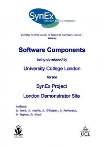
Figure 2.1. Architecture of a CBS with a global-level monitor
According to the existing work, monitoring is usually performed at the global-level where a central monitor observes the whole component-based software (CBS). Figure 2.1 presents the generic architecture of a CBS with a global-level monitor. In this thesis, we propose that each component should have a component-level monitor embedded into the component (not shown in Figure 2.1).
12
2.2 SECURE SOFTWARE DEVELOPMENT PROCESSES
In event monitoring (henceforth referred to as E-monitoring), the monitoring code is executed with the monitored code (target software), and the monitor uses the resources of the target software. Whenever an event is generated, the control is transferred to the monitor which processes the event and returns the control back to the monitored program (also referred to as the inline monitor in [44]). In time monitoring (henceforth referred to as T-monitoring), the monitoring code is executed as a separate process or thread (also referred to as the offline monitor in [44]). Separate execution allows the T-monitor to effectively and independently keep track of time and act whenever necessary without having to wait for the monitored program. This enables the T-monitor to observe and detect violations of time-critical constraints. T-monitors observe the changes in variable values of the monitored program instead of waiting for these values to be passed on to them through events. The traditional approach to develop monitors for any software is to first develop the software itself (or acquire it from a third-party) and then build a monitor. A monitor for a CBS is designed and developed in a similar fashion. An asset can be defined as a resource belonging to the system of which the software is going to be a part. An asset can be information (e.g., data), service (e.g., online service), or any other tangible entity affected by the software.
2.2
Secure Software Development Processes A component with an embedded monitor based on security specifications can be
developed by performing the following three major activities: 1. Developing a secure component. The software component should be developed in a secure manner from the beginning. This requires that the security specifications are stipulated and followed in all the development phases. The dynamic behavior (as represented in the design) of the software component must include all the constraints imposed by these security specifications.
13
2.2 SECURE SOFTWARE DEVELOPMENT PROCESSES
2. Developing a specification-based security monitor. Security specifications stipulated while developing the component should be used to design the monitor. This will enable the monitor to observe the component’s security related behavior and identify any deviations from the one specified to design the component. 3. Embedding the security monitor into the component. The monitor should be developed in a way such that it is a part of the monitored component. Components should also be instrumented to generate monitoring events which will pass information about the current state of the component to the monitor. We require the above activities to be part of a secure software development (SSD) process for developing a secure component with an embedded monitor. Moreover, the activities have to be performed in parallel with the actual development of the software. In the following paragraphs, we assess the SSD processes reported in the literature (e.g., [8, 51-60]) based on these activities. The touch points identified in McGraw’s software development process [8] include eliciting abuse cases [61] and security requirements. McGraw also suggests performing risk analysis in both the requirements and design phases [11]. Microsoft Software Development Lifecycle (MS SDL) [51] specifies security mechanisms during the requirements phase, follows secure design guidelines and secure coding standards, and performs multiple assurance activities. MS SDL also proposes to use threat modeling and risk analysis during the design phase. Among the proposed secure software development processes and methodologies, Comprehensive, Lightweight Application Security Process (CLASP) [54] is the most comprehensive one with respect to stipulating security specifications [1]. CLASP proposes to use misuse cases [62] and identify mitigations (security specifications). It also suggests performing threat modeling and risk analysis in both requirements and design phases [63]. CLASP recommends identifying security specifications for requirements, design, and implementation phases. It proposes annotating class diagrams with security information and suggests that secure design guidelines and secure coding standards be followed [7, 64-67].
14
2.2 SECURE SOFTWARE DEVELOPMENT PROCESSES
In its assurance phase, CLASP suggests to perform inspections, static code analysis, and security testing. In [52], Appropriate and Effective Guidance for Information Security (AEGIS) is proposed. AEGIS focuses on the requirements and design phases and does not specify any secure development activity for other phases. The approach allows for identifying security vulnerabilities and threats. Similarly, the Secure Software Development Model (SSDM) [53] mainly stresses on the requirements phase where the major activity is threat modeling. A security policy is specified based on the identified threats and can be used as a guideline during design. It does not provide any implementation phase activity, and penetration testing [8] is the main assurance activity. The Secure Software Development Process Model (S2D-ProM) [55, 68] proposes multiple, but alternate, development activities. These activities include identifying threats (in the requirements phase), specifying security mechanisms, performing risk analyses in requirements and design phases, and following secure coding standards. The secure development activities in the Team Software Process Secure (TSP-Secure) [60, 69] include identifying risks, stipulating security specifications, constructing a secure design, conducting code reviews, performing static analysis with the help of tools, and security testing. The process proposed by Apvrille et al. [57] models threats, performs risk analysis, and specifies security requirements in the requirements phase. The authors suggest using UMLsec and security patterns in the design phase of software development. They also point out that a secure programming language and already established algorithms should be used. Security Quality Requirements Engineering (SQUARE) methodology [70] initially focused on developing security requirements in the requirements phase. This methodology was then enhanced into SQUARE+R [71] to incorporate risk analysis in all phases of the development to ensure security. SQUARE+R also suggests using static and dynamic code analysis tools for the security assurance phase. The authors also argue that SQUARE+R is more suited for component and agile development.
15
2.2 SECURE SOFTWARE DEVELOPMENT PROCESSES
The Secured Software Development Process (SSDP) [72] separates the development activities into management and technical domains. The main technical development activities include misuse cases, threat modeling and risk analysis of design, and fuzz and penetration testing. They suggest maintaining a database of security vulnerabilities that can be consulted during development. From the various security mechanisms, the authors emphasize more on access control and authentication. Othmane et al. [73] extend the agile software development process with secure development activities. The authors divide these activities in the inception (prerequirements), construction (requirements, design, and coding), and transition (assurance) phases. Activities belonging to the pre-requirements phase are threat modeling, risk analysis, and identification of security goals. During the construction phase, the authors propose to develop user security stories to mitigate any identified threats in an iterative manner. Development of these stories involves eliciting security requirements based on threats, security test scenarios, and security features. The final step in the construction phase is testing the implemented security features based on the already specified test scenarios. The transition (assurance) phase involves generic security testing and analysis techniques. Baca and Carlsson [74] propose an agile process for secure software development which includes only those development activities that various professional developers actually use. A survey was conducted just for this purpose in which the developers were asked to select development activities based on their cost and benefits. Security requirements, abuse cases, countermeasure graphs, design inspections, static code analysis, and secure coding standards were used by many of the interviewed developers. In contrast, risk analysis, threat modeling, UMLSec, and security tools, among others, were not preferred due to their high cost and/or low benefit. An overview of the activities proposed by each of the above mentioned SSD processes is presented in Table 2.1. As it is evident from the discussion of existing processes presented above, most existing secure software development processes endeavor to identify security specifications in the requirements or design phases. After the vulnerabilities have been identified,
16
2.2 SECURE SOFTWARE DEVELOPMENT PROCESSES
appropriate security specifications are stipulated to avoid or remove these vulnerabilities. Among the SSD processes reported in the literature, MS SDL and CLASP provide the most comprehensive guidance for developing secure software. A comparative study of many existing SSD processes is presented in [1].
Table 2.1. Summary of existing secure software development processes
McGraw’s SDL [8]
MS SDL [51]
SSD Activities for the Requirements Phase
SSD Activities for the Design Phase
SSD Activities for the Implementation Phase
Specify abuse cases & security requirements. Risk analysis.
Risk analysis.
None
Identify critical components, Use secure coding Identify of interfaces, security attack surface, design methods, & standards. Code objectives & required security completion criteria. Threat reviews. Use testing & mechanisms. Define exit criteria. modeling. Risk analysis. Define static code analysis secure architecture. tools.
Risk analysis. Threat Modeling. Identify attackers & attack surface. CLASP [54] Specify misuse cases with their mitigations & security features.
Follow design guidelines. Annotate class diagrams with security information. Threat modeling. Risk analysis.
Risk analysis. Identify assets, abuse cases, & security requirements. SSDM [53] Threat modeling. Security policy.
Design decisions based on security requirements. Follow the security policy.
AEGIS [52]
S2D-ProM [55]
Use secure coding standards. None None
Use security standards. Risk Use security modeling language Use secure coding analysis. Identify vulnerabilities. & security patterns. Risk analysis. standards & a secure Specify security features. Design reviews. Model checking. language.
TSP Secure Threat modeling. Specify abuse Design patterns. State machine Use secure coding [60] cases. Risk Analysis. bases design & verification. standards. Apvrille & Identify security objectives. Threat Secure programming Pourzandi modeling. Specify security Use UMLsec & security patterns. language & known [57] requirements. Risk analysis. algorithms. SQUARE+R Security requirements & risk Static & dynamic Risk analysis [71] analysis. analysis. SSDM [72] Othmane et al. [73] Baca & Carlsson [74]
Misuse cases and formal methods. Threat modeling & risk analysis.
Security testing.
Inception Phase: Threat modeling, risk analysis, & security goals. Construction Phase: Security user stories and security features. Transition Phase: Testing and analysis Security requirements & role matrix
Countermeasure graphs, abuse Static code analysis & cases, requirement inspection, & secure coding assumption documentation. standards.
17
2.3 SOFTWARE SPECIFICATION LANGUAGES FOR ATTACK SPECIFICATIONS
None of these processes identify activities related to developing a specificationbased security monitor or embedding such a monitor in the software component. Therefore, we need to identify development activities such that a specification-based security monitor can be developed and embedded in the component. These development activities should describe the changes that need to be made to the static structure and dynamic behavior of the software under monitoring. We also need to define the behavior of the monitor.
2.3
Software Specification Languages for Attack Specifications Hussein et al. [75] propose a UML profile called UMLintr for specifying attack
scenarios. This profile presents how UML stereotypes, tagged values, use case diagrams, package diagrams, class diagrams and state machine diagrams could be used to represent intrusions during different stages of the software development. Tsai and Huang [76] present an attack signature exchange model for different intrusion detection systems (IDSs), including Snort. They propose the static structure for attack signatures using UML classes. The attack signatures are first converted into XML format which are then transformed into the IDS specific signature. Abstract State Machine Language (AsmL) is a textual software specification language and has also been utilized to specify attack scenarios in [77-79]. The attack scenarios specified in AsmL by [77, 78] are converted automatically through an especially developed compiler. These scenarios are then used with the IDS Snort. AsmL attack scenarios in [79] also include context information. This enables the IDS to detect multi-step attacks, as well. Whittle et al. [80] propose to use UML use cases and sequence diagrams to represent attacks on a software and possible mitigations. The UML model is then converted into finite state machines which are then executed on a model checker that verifies whether the suggested mitigation for a particular attack is correct. Morais et al. [81] use UML interfaces to represent the attacker, attack, and victim to make the attack script more usable. Ariss and Xu [82] model attacks with state machine diagrams. Their main objective is to
18
2.4 DESIGN OF COMPONENTS WITH EMBEDDED MONITORS
represent attacks in a manner understandable to both software and security engineers. Ariss and Xu’s [82] work is closer to ours as they also use state machine diagrams with a view for closing the gap between software and security engineering.
2.4
Design of Components with Embedded Monitors Many approaches have been proposed in the literature to develop components with
embedded monitors. We investigate these approaches with respect to the design aspect (interactions) of a monitor and the component to be monitored. According to the approach presented in [38], each component has a service layer which notifies abnormalities detected in the functional behavior. We too advocate that each component should have a security monitor. Bisadi and Sharifi [39] propose that each node (one or more components) in a distributed system have an additional healing layer that monitors the (black box) behavior of component(s) where a number of components can be observed by a single monitor. Instead, we develop separate component-level monitors to detect deviations from the security specifications. Haydarlou et al. [40] suggest an approach to develop self-monitoring autonomic systems. Their work focuses on where monitoring events should be inserted in the use case representation of a software system. We enhance state machine diagrams for incorporating monitoring events. Tan [41] proposes to compose the monitor with the system model to form a self-monitoring model. In our approach, we also enhance the model (UML class and state machine diagrams) to include monitoring related aspects. However, we observe security behavior and have separate monitors for each component. Kuang et al. [42] propose to develop self-monitoring systems that monitor for functional compliance and reliability while we observe security behaviors. Kuang et al. also do not develop a separate monitor for each component. Barnett and Schulte use AsmL to write executable specifications for components [83]. These specifications are executed along with the software to identify deviations in the behavior. Their approach is for already
19
2.4 DESIGN OF COMPONENTS WITH EMBEDDED MONITORS
developed components; moreover, they use component interfaces and do not observe the security behavior. In the event-based tracking model proposed by Gao et al. [36], each component has its own tracker. This tracker only passes tracking events to the tracking agent which is responsible for multiple components. These trackers are not developed along with a component, are not embedded into the component, and do not observe security behaviors. Another closely related work is the monitor-oriented programming (MOP) [83, 84] where properties to be monitored are specified using logical formalisms. These properties are then compiled into checks that are evaluated during runtime. We do not use any logical formalism to specify properties that are to be monitored and propose to use checks based on variables in the UML state machine diagrams. These checks are then implemented as part of the monitor along with the components. A separate state machine is implemented in the monitor that is used to observe security specifications. Lanoix et al. [85] propose to enhance the dependability of a CBS by attaching additional components that facilitate security, safety, and fault-tolerance. These additional components are responsible for the complete system. Mannava and Ramesh [86] suggest a software architecture for self-healing and self-configuring software. There are two layers in their architecture: the first layer is for the server and the second layer is for the distributed system. The monitoring module in these layers is responsible to observe the complete system. Reza and Mazumder [87] suggest an enhanced architecture for the Android operating system to incorporate security measures. These are primarily based on an intrusion detection module within the operating system to identify malicious behaviors of any of the applications running at a given time. The monitor, in this case, is completely independent (part of the operating system) of the target application(s). All of the above mentioned works (except [85] and [87]) compare the observed behavior of the software with its functional specifications. These works consider the software as a black box and perform their analysis based on operating system events, such
20
2.5 SECURITY MONITORING TECHNIQUES
as file access, memory access, and input/output messages. Security vulnerabilities cannot always be monitored by such high-level operating system events only. The software needs to send monitoring related information explicitly only to the monitor for effective security monitoring. Moreover, in these works, a monitor (security or otherwise) is not made part of each individual component. Usually a specification-based monitor is developed after the CBS is built and not in tandem with it.
2.5
Security Monitoring Techniques Many security monitors have also been proposed in the literature [17-26, 75, 88,
89]. These can be broadly categorized into intrusion detection systems (IDSs), monitors that detect the effects of successful exploitation of vulnerabilities, and monitors that identify deviations from the specified behaviors. In the following subsections, we discuss these security monitors from two aspects: (1) the design of the monitor i.e., the interactions of the monitor with the monitored software and (2) the monitoring technique i.e., how the monitoring is performed. 2.5.1 Techniques to Detect Intrusions Among the many proposed IDSs, we only discuss the ones that either use state machines or are developed along with the monitored software [75, 88, 89]. More specifically, in [89] the authors specify the steps of an attack using State Transition Analysis Technique Language (STATL) which is a state-based attack specification language. The behavior of the software is captured by events reported in audit logs of the operating system. These events are employed for transitioning through the attack specifications in the IDSs, USTAT or WinSTAT. In our proposed approach, we observe the behavior of the software under monitoring instead of attack steps. We also perform both event and time monitoring and instrument the software to generate monitoring events that are then used to observe the software component’s behavior (instead of using operating system events).
21
2.5 SECURITY MONITORING TECHNIQUES
An approach to develop software that can identify intrusions or attacks is proposed in [88]. The authors suggest performing E-monitoring and developing the monitor along with the software. Our approach can be used to observe the behavior of the software. In addition, we also perform T-monitoring which is required to effectively observe timecritical constraints. Hussein et al. [75] suggest developing software that can detect intrusions. Their monitor uses operating system events and network traffic to observe the behavior of the software to identify attack steps. Although the software includes a monitor in the form of a separate component, the software is independent of the monitor. Open Web Application Security Project (OWASP) proposes an approach (AppSensor) to embed “sensors” in an application [90, 91]. These sensors collect data about the user’s actions during the execution of the application. A certain number of abnormal actions performed by the user are considered to be an attack and the software takes appropriate measures. 2.5.2 Techniques to Identify Successful Exploitation of Vulnerabilities Many security monitors proposed in the literature observe the behavior of software for indicating that a vulnerability has been successfully exploited. However, these monitors focus on detecting vulnerabilities resulting from the violations of security specifications that are specific to the implementation phase (e.g., [17-25]). Buffer overflow, dangling pointers, format string bugs, SQL injections, cross site scripting, and memory leak are examples of vulnerabilities observed by these monitors. An extensive survey of such monitors has been reported in [92]. In what follows, we discuss only those works that instrument the code (source or object) to generate monitoring events (as our approach is also to instrument source code). Aggarwal and Jalote [17] propose a technique to observe buffer overflow and timeof-check-to-time-of-use vulnerabilities. Their monitor can be utilized for any software whose object code is available. They perform monitoring in a separate process which has a copy of the return address to compare when the function returns. Gupta et al. [18] suggest a
22
2.5 SECURITY MONITORING TECHNIQUES
technique where the object code of each function is instrumented at the beginning and end. The instrumentation is to save the function’s return address in a separate stack. This address is compared with the actual return address when the function is about to return to detect buffer overflows. Li and Chiueh [19] propose to augment the object code, such that a canary word is placed at the end of the list of arguments of format functions. If the canary word is accessed at runtime, then it is an indication that format string attack has happened. Bandhakavi et al. [20] extract the intended parse tree of an SQL query. This tree is compared with the parse tree generated at runtime of the query that has been provided as input. Buehrer et al. [26] suggest a similar approach; however, the comparison is performed before and after the inclusion of user input into the parse tree. Both of these approaches instrument object code, and their only objective is to detect exploitation of SQL injection (SQLI) vulnerabilities. Zheng et al. attempt to monitor heap buffer overflows by intrumenting code [93]. The monitoring is performed in a concurrent manner. To achieve this goal, they introduce a separate thread for monitoring. Multiple works have been reported that modify the compiler to insert the object code for monitoring a specific security vulnerability, such as buffer overflow or SQL injection [27-34]. All these works perform E-monitoring. Moreover, the monitoring code is injected during compile time and not during the development of the target software. The above approaches focus on detecting one or two vulnerabilities, which mainly result from insecure implementation practices. Hence, one would have to use a number of monitors to observe the software behavior, ultimately covering vulnerabilities due to violations of security specifications during the implementation phase. In our approach, we monitor the behavior of the component againt security specifications. Most of the constraints imposed by these security specifications can be represented as checks and state machines. Our approach compares the observed behavior of the component against these checks and state machines enabling us to cover a wide range of vulnerabilities.
23
2.5 SECURITY MONITORING TECHNIQUES
Existing security monitors that claim to detect successful exploitation of vulnerabilities are developed independently from the monitored software system (e.g., [17, 18]). The developers of these monitors usually do not have development artifacts resulting from or used at each development phase (e.g., requirements or design). Sometimes they do not even have access to the source code to be monitored (i.e., implementation phase). We, however, propose to design the monitor while developing the overall software when the development artifacts are available. Developing the monitor in such a manner can enable building a comprehensive monitor for observing security specifications based on the actual requirements and design documents. With respect to instrumentation, mostly object or binary code is instrumented to generate events to transfer information required for monitoring in the absence of source code (e.g., [19]). Understanding the behavior of any reasonably large software through its object code is a heavy reverse engineering task. Moreover, identifying the correct location in the object code to instrument the event generation code is technically difficult. Given that, existing monitors lack completeness in terms of observing the software according to its security specifications. We instrument source code by using requirements and design artifacts in our proposed approach. Some of the existing monitors also observe the state of the monitored software. Their primary objective is to identify any similarities with a state that is consistent with a successful exploitation of a vulnerability. For example, when a buffer overflow vulnerability is successfully exploited, the function return address or other data adjacent to the variable (buffer) that has overflowed its bounds might change. A number of approaches have been proposed to observe these kinds of changes. For example, a monitor proposed by Aggarwal and Jalote [17] checks for the function return address before and after the function returns. If a change is detected, then it would imply that a buffer overflow vulnerability has been exploited. Such approaches have two major drawbacks. First, the vulnerability is detected after it has been successfully exploited. Although the software can be fixed when the vulnerability is found, major consequences could have already been
24
2.5 SECURITY MONITORING TECHNIQUES
inflicted. Another drawback is that the location of the vulnerability cannot be determined by the monitoring results. For example, in the above scenario, the change in the return address is detected when the function returns. Here, the vulnerable code statement could be located anywhere in the function. Hence, although the monitor is able to detect the exploitation, it is unable to locate that vulnerability in the source code so that it may be removed. In our approach, we try to point out any deviations from the specified security behavior. The monitoring event, in our case, can be used to pinpoint the code statements that caused the violation. 2.5.3 Techniques for Monitoring Software Behaviors Wang et al. [94] instrument the source code with assertions to observe the behavior of software. These assertions are checks that are evaluated at runtime to monitor the correct behavior of the software (against the security specifications). In addition to checks, we also observe the sequence of actions performed by the software and compare them with the specified sequences. We represent these sequences by using state machines. Michael and Ghosh [95] use system calls to monitor the behavior of software. However, their monitor is limited only to unauthorized access and elevation of privileges. We try to monitor all those security specifications that can be represented by either checks or state machines (or both). They perform only E-monitoring while we use both event and time monitoring which enables us to monitor time-critical constraints. Their monitor is external to the monitored software observing it at the global-level, while ours is embedded in the monitored software and performs monitoring at the component-level. Ko et al. [96] observe the behavior of software through “audit trails” which are logs of system calls made by the software. The intended behavior of the software specified by the policy is converted into logical expressions which are used to verify the observed behavior. In our approach, we do not depend on system calls and use variable values to verify constraints.
25
2.6 SUMMARY
Vanoverbergehe and Piessens [97] propose an approach to handle exceptional situations that may arise during the execution of a secure software. Their aim is to distinguish between malicious and legitimate violations of a security policy. Their approach is event-based and introduces checks before those segments of code that contain security conditions. When the check foresees a violation of the upcoming security condition, a warning message is displayed. This warning asks the user for permission to proceed after notifying the user about the violation that will occur if the execution of the software proceeds with the current set of inputs. In our approach, we also observe time constraints and use both event and time monitoring techniques. Attestation is a technique that is typically used to verify properties of embedded systems [98-100]. Usually, binary code is verified against a pre-defined set of properties which may also include security. Gu et al. [101] suggest a framework to verify source code too. However, software attestation, although having the same purpose, is different from our proposed work as we try to monitor the behavior of the software while it is executing in the deployment environment.
2.6
Summary The analysis of the aforementioned related works reveals that existing SSD
processes do not use security specifications beyond the testing phase. They do not identify development activities that can be used to design and embed a specification-based security monitor in a component. There is a gap between security and software engineers, especially with regards to specifying security during different phases of software development and monitoring phases. The designs of the self-monitoring components suggested in the literature indicate that the monitor is not part of the component and is a distinct entity (component). Most of the security monitoring work focus on detecting attack steps or the effects of successful exploitation of security vulnerabilities. Moreover, the vulnerabilities whose effects are detected are the results of not following security specifications related to the implementation phase (i.e., insecure implementation practices). Such monitors do not
26
2.6 SUMMARY
observe constraints resulting from security specifications belonging to the requirements or design phases. Research works that compare the observed and specified behavior of software only monitor for valid values of variables and do not observe constraints on sequences of actions or time-critical constraints. In light of the above mentioned issues, it becomes necessary to design a development methodology (as part of a generic SSD process) that can be utilized to enhance a component such that the component has an embedded specification-based security monitor. The structure of such a component and the monitor and their interactions (operation of the monitor) also needs to be developed. Moreover, a security monitoring technique with algorithms has to be designed that can be used to observe different kinds of behaviors. These observed behaviors should then be compared with various types of constraints resulting from requirements and design level security specifications. In the next chapter, we propose a secure software development process for developing more secure software.
27
Chapter 3 Bringing Software and Security Engineering Together We attempt to bring software and security engineering together in two distinct ways. First, we propose a secure software development process that includes a security monitoring phase after deployment. We further expand this process in Chapter 4 to introduce activities specific to building a specification-based security monitor after the design of the software itself is complete. As discussed in Chapter 2, security monitors can look for attack steps too. In this chapter, we propose to model attacks in a software specification language, namely UML state machine diagrams [102]. This representation is then converted into Snort (an intrusion detection system) rules. This link between software specification and intrusion detection would allow the software and security engineering domains to come closer. The rest of this chapter is organized as follows: Section 3.1 elaborates upon the secure software development process. Section 3.2 describes the methodology to first represent attacks in UML state machine diagrams and then convert them into Snort rules. Section 3.3 concludes this chapter with the summary.
28
3.1 A SECURE SOFTWARE DEVELOPMENT PROCESS
3.1
A Secure Software Development Process The primary and essential requirement to develop any secure software, and then
maintain and improve its security posture, is to follow a secure software development process. In this section, we propose a new secure software development process that includes activities essential for achieving a more secure software. This process includes activities necessary for developing and embedding a specification-based security monitor into the software. However, activities related to monitor development are discussed in Chapter 4. The process contains two distinct views of software development: activity view and artifact view. The activity view describes the various development activities while the artifact view identifies the artifacts produced during development. The security posture of each development artifact should also be assessed before it can be used. Therefore, as part of the process, we propose a method to assess the security posture of requirements, design, or code. This section is organized as follows: Section 3.1.1 describes the activity view of the process, while Section 3.1.2 presents the artifact view of the process. Section 3.1.3 elaborates the quantification method to assess the security posture of a development artifact. 3.1.1 Activity View The process addresses requirements engineering, design, implementation, assurance, monitoring, and rework phases. This process can be employed as a sequential (waterfall) or an iterative (spiral) process for development. Moreover, it contains both functional and secure software development activities (e.g., specification of use cases vs. specification of abuse cases). The activity view presents the development activities for each of the phases and the sequence in which they should be performed (Figure 3.1). In the following subsections, we elaborate on these activities.
29
3.1 A SECURE SOFTWARE DEVELOPMENT PROCESS
3.1.1.1
Requirements Engineering Phase It has been estimated that a mistake introduced in the requirements engineering
phase, if not removed immediately, can cost up to 200 times more to correct in later stages of development [50]. It can be assumed that correcting a software security vulnerability will be equally expensive. Hence, this phase must receive special attention and have the following activities to derive complete functional and security requirements. R1.
The behavior and deployment environment of the software should be specified employing use cases, along with detailed functional requirements (diagrams/text).
R2.
Abuse cases should be specified. Information about software assets, attackers, attackers’ interests, attackers’ resources, attack surfaces, and threats to existing software of the same domain must be collected. A threat model ought to be developed in light of the aforementioned information.
R3.
Risk analysis should be performed on the identified threats to identify the potential damage that each of them can cause to different assets. This information ought to be used to prioritize threats.
R4.
Security requirements necessary to mitigate identified threats should be specified.
R5.
Security mechanisms for each security requirement should be selected. It may be possible that more than one security mechanism is able to fulfill a security requirement. Moreover, different security mechanisms may offer varying levels of assurances. The implementation and social cost (e.g., usability) of a security mechanism might also be different. An appropriate security mechanism should be selected by considering the above mentioned issues. This selection procedure should involve all stakeholders.
R6.
Detailed functional requirements of the selected security mechanisms (e.g., strength of the password) must be specified. Note that the functional requirements of a security mechanism should be considered as security requirements themselves.
30
3.1 A SECURE SOFTWARE DEVELOPMENT PROCESS
Phase Requirements Engineering
R1. Specify functional requirements employing use cases R2. Specify abuse cases and model threats R3. Perform risk analysis on threats R4. Specify security requirements to mitigate threats
R5. Select security mechanisms for security requirements R6. Specify functional requirements for selected security mechanisms R7. Assess security index
If the security index is NOT within acceptable range
If the security index is within acceptable range R8. Perform inspections on the completed requirements specifications
Design
D1. Construct detailed design
D2. Perform design inspections D3. Remove security vulnerabilities in the design D4. Assess if another round of design inspections is required
If another round of inspections are required
If another round of inspections is NOT required D5. Design specification-based embedded security monitor
Implementation I1.Selecting a secure programming language I2.Following secure coding standards and guidelines I3.Unit testing
Assurance A1.Code inspections and static analysis A2.Generating test cases A3.Integration, acceptance, and penetration testing
Monitoring and Rework
MR1.Observe software’s behavior for deviations from specifications MR2.Locate underlying vulnerabilities for identified deviations MR3.Perform rework to remove vulnerabilities
Figure 3.1. Activity view of the Process
R7.
A threshold of acceptable security can be defined by using the security index [3] which provides a measure of the current security state of a development artifact.
31
3.1 A SECURE SOFTWARE DEVELOPMENT PROCESS
The security index of the requirement specifications artifact should be within the threshold. If a weak security mechanism is selected to fulfill a security requirement, then its weakness may be treated as a vulnerability while calculating the security index. The method for calculating the security index is elaborated in Section 3.1.3. If the calculated security index is less than the threshold, then stronger security mechanisms should be employed to satisfy corresponding security requirements. Furthermore, security mechanisms for lower-risk threats may also be included to improve the security index. R8.
The completed requirements specification artifact ought to be inspected (multiple times, if required) for identifying and removing vulnerabilities. Security vulnerabilities reported in similar existing software can be used as a checklist for inspections.
3.1.1.2
Design Phase Design is the representation of decisions taken to fulfill requirements. Design
specifies two aspects of the software: static structure and dynamic behavior. The design phase in the process has the following steps: D1.
Detailed functional design (including design of security mechanisms) should be specified by following secure design patterns and secure design guidelines.
D2.
Inspections should be performed on the completed design to identify any vulnerabilities. Security vulnerabilities reported in the design of similar existing software can be used as a checklist.
D3.
Identified vulnerabilities should be removed.
D4.
If a large number of security vulnerabilities are identified in the first round of inspections (Activity D2), then it might be a worthwhile idea to perform another round of inspections. This would entail repetition of Activities D2, D3, and D4.
D5.
When the design is completed, steps should be taken to develop a specificationbased security monitor and embed it into the software. If the software is a
32
3.1 A SECURE SOFTWARE DEVELOPMENT PROCESS
component-based one, then each component should have its own independent security monitor embedded into it. The details of the development activities required to develop such a monitor and then embedding it into the software are discussed in Chapter 4. 3.1.1.3
Implementation Phase Design is translated into code during implementation. Following are the activities
that need to be performed during implementation to achieve secure code: I1.
A secure programming language, while keeping in view the programming requirements of the software under development, should be selected.
I2.
Secure coding standards and guidelines should be followed to avoid source code vulnerabilities.
I3.
Unit testing needs to be performed with security concerns in mind. Security vulnerabilities reported in similar software should be used as a reference.
3.1.1.4
Assurance Phase During the assurance phase, the software is checked to find if it meets the
requirements. The following activities should be performed during this phase: A1.
Code must be inspected (based on the checklists of the previously reported vulnerabilities) to identify software and security vulnerabilities. Static analysis tools should be used to find vulnerabilities. The discovered vulnerabilities must be removed through rework.
A2.
Test cases should be developed based on functional and security requirements.
A3.
Integration and acceptance testing needs to be performed based on the security requirements. Penetration testing should be performed based on the known vulnerabilities and the potential attacks that the software may encounter. Any security vulnerabilities found must be removed.
33
3.1 A SECURE SOFTWARE DEVELOPMENT PROCESS
3.1.1.5
Monitoring and Rework Phase Once the software is deployed in its operational environment, its behavior should be
continuously monitored to identify any deviations from its functional and security requirements. The major activities in this phase are described below: MR1. Observe the behavior of the software through monitoring and verify it against functional and security requirements to identify any deviations. MR2. Locate the vulnerabilities in requirements, design, or code which are the root cause of any identified deviations. MR3. Perform rework to remove vulnerabilities (on the deployed software or on future versions). All these three activities need to be continuously performed for the life of the software. 3.1.2 Artifact View The information contained in the current artifacts is used to develop new artifacts. Moreover, each development activity in the process either results in a new artifact or enhances an already existing one. This artifact evolution can be represented using artifactartifact and activity-artifact relationships. This evolution needs to be explicitly defined to guide software developers. For the artifact-artifact relationship, we use “
” to represent
that the target artifact is produced by taking the source artifact(s) as input(s). Figure 3.2 presents these relationships while Table 3.1 shows the activity-artifact relationships. Initially, in the requirements engineering phase, Information about assets and attackers and Use cases are developed which, in turn, are used to produce the Threat model. Security requirements are identified based on the threat model and Security mechanisms are selected to fulfill these security requirements. The Use cases and selected Security mechanisms are used to develop Detailed functional and security requirements.
34
3.1 A SECURE SOFTWARE DEVELOPMENT PROCESS
Phases Requirements Engineering Assets, attackers, and abuse cases
Use cases
Threat model
Prioritized threats
Security requirements
Selected security mechanisms
Detailed functional and security mechanisms’ requirements
Design
Design
Enhanced design for monitoring
Implementation Code
Assurance
Monitoring and Rework
Checklist of previously reported vulnerabilities
Final code
Test cases
Identified security vulnerabilities
Figure 3.2. Artifact view of the development process: artifact-artifact relationships
35
3.1 A SECURE SOFTWARE DEVELOPMENT PROCESS
Table 3.1. Artifact view of development process: activity-artifact relationship Activities None R1 None R2 R3 R4 R5 R6 R7 R8 D1 D2 D3 D4 D5 I1 I2 I3 A1 A2 A3 ME1 ME2 ME3
Input Artifacts
Output Artifact Use Cases Abuse cases, assets, attackers, and threat model Threat model Prioritized threats Prioritized threats Security requirements Security requirements Selected security mechanisms Use cases and selected security mechanisms Detailed functional and security mechanisms’ requirements Detailed functional and security mechanisms’ requirements None Detailed functional and security mechanisms’ requirements Detailed functional and security mechanisms’ requirements Detailed functional and security mechanisms’ requirements Design Design Design Design Design Design Design Design and any identified security vulnerabilities Enhanced design for monitoring None None Enhanced design for monitoring Code Code Code Code and checklist of previously reported vulnerabilities Final code Detailed functional and security mechanisms’ requirements Test cases and use cases Final code and test cases Final code Final code Identified security vulnerabilities Identified security vulnerabilities, detailed functional and Detailed functional and security security mechanisms’ requirements, enhanced design for mechanisms’ requirements, enhanced monitoring, and final code design for monitoring, and final code Detailed functional and security mechanisms’ Detailed functional and security requirements, enhanced design for monitoring, and final mechanisms’ requirements, enhanced code design for monitoring, and final code
In the design phase, Detailed functional and security requirements from the requirements phase is utilized to develop the Design of the software. This design is then enhanced to include monitoring events and the specification-based security monitor. The enhanced design serves as the foundation for implementing the Code in the next phase of development. In the assurance phase, Test cases are developed based on Use cases and Detailed functional and security mechanisms’ requirements. Moreover, a checklist of previously reported vulnerabilities in similar software is developed and is used for inspections and
36
3.1 A SECURE SOFTWARE DEVELOPMENT PROCESS
static analysis. The corrected code, after removing vulnerabilities found through assurance techniques, results in Final code. In the monitoring and rework phase, the behavior of the deployed software is observed and any security vulnerabilities are identified. The enhanced design (including the monitor) is updated to remove the identified vulnerabilities. 3.1.3 Quantifying Security In this section, we propose a methodology which will enable developers to evaluate the security state of a particular development artifact. We propose to perform this evaluation after requirements have been finalized (Activity R7). However, this evaluation may also be performed in other phases if the software developers feel the need to do so. Security evaluation, once the requirements have been completed, would allow the development of more secure software. Particularly, the evaluation can help in prioritizing security vulnerabilities based on the potential damage they can cause. Quantified information about vulnerabilities is important because if vulnerabilities are not corrected in the early requirement phase, the cost of correcting them might increase tenfold with every additional development phase [103]. The National Institute for Standards and Technology (NIST) suggests the Common
Vulnerability Scoring System (CVSS) to assess the severity of a particular vulnerability [104]. The CVSS calculates two scores: base and temporal. The base score is the product of exploitability and impact of the vulnerability and some constant values. The temporal score is the products of the base score, exploitability, remediation level, and confidence report. The temporal score is meant to be calculated after the vulnerability has been researched and appropriate measures have been developed to avoid it. We, in the following paragraphs, propose another way to calculate the severity of a vulnerability based on asset values that can be exploited. The proposed way allows taking into account the asset values of a particular software system. Vulnerabilities can be denoted as V1, V2, …, Vn (where Vn is the nth vulnerability). Vulnerabilities can occur more than once, and all such occurrences need to be identified.
37
3.1 A SECURE SOFTWARE DEVELOPMENT PROCESS
We can represent vulnerability occurrences as VXO1, VXO2, …, VXOp (where VXOp is the pth occurrence of vulnerability X). The first step in the quantification methodology is to identify all such occurrences of vulnerabilities in an artifact. Suppose that there exist three vulnerability occurrences that can be represented as V1O1, V2O1, and V3O1. To be able to decide effectively about potential damage that can be caused by vulnerabilities, we need to identify assets and their values, the relationships between assets and vulnerabilities, the likelihood of each vulnerability being exploited, the potential damage caused by each vulnerability occurrence to each asset, and the cost to remove a vulnerability occurrence. Assets can be represented as A1, A2, …, Ar (where Ar is the rth asset). For example, a software has customer account information (CAI), online service (OS), and printing facility (PF) as assets. These assets can be represented as ACAI, AOS, and APF, respectively. Assume that V1O1 threatens ACAI and AOS, V2O1 threatens APF, and V3O1 threatens AOS. The threat posed by any vulnerability can range between 0 and 1 (0 meaning no threat and 1 meaning maximum threat). This threat also depends on how difficult it is to carry out a successful attack. The threat posed by a vulnerability VXOY can be represented as TVXOY. The maximum possible damage that can be caused by a vulnerability occurrence to an asset can be represented as DArVXOY (where DArVXOY is the damage caused to the rth asset by the yth occurrence of the xth vulnerability). DArVXOY is the product of the value of an asset and the threat posed by the vulnerability being exploited to cause harm to that asset (based on vulnerability plausibility in [105]). Hence, the values of DACAIV1O1, DAOSV1O1, DAPFV2O1, and DAOSV3O1 would be ACAI * TV1O1, AOS * TV1O1, APF * TV2O1, and AOS * TV3O1, respectively. The cost of removing a vulnerability occurrence can be represented as CVXOY (where CVxOy is the cost to remove the yth occurrence of the xth vulnerability). Table 3.2 presents the damage caused by vulnerabilities V1O1, V2O1, and V3O1 to the assets ACAI, AOS, and APF. The blank cells in the table indicate that a particular asset is not affected by a vulnerability.
38
3.1 A SECURE SOFTWARE DEVELOPMENT PROCESS
Table 3.2. Damage and removal cost for vulnerabilities
ACAI Assets
AOS APF Total Damage (TDVXOY) Removal Cost (CVXOY)
Vulnerability Occurrences V 1 O1 V2O1 Damage: ACAI * TV1O1 Damage: AOS * TV1O1 DACAIV1O1 + DAOSV1O1 CV1O1
V3O1 Damage: AOS * TV3O1
Damage: APF * TV2O1 DAPFV2O1 CV2O1
DAPFV2O1 CV3O1
The total potential damage caused by a vulnerability occurrence can be represented as TDVXOY (where TDVxOy is the total potential damage caused by the yth occurrence of the xth vulnerability) and calculated as shown in Equation 1, where m is the number of assets. The table second last row of the table identifies the total damage caused by a particular vulnerability while the last row gives the removal cost of each vulnerability. Hence, in the case of our example, the values of TDV1O1, TDV2O1, and TDV3O1 will be DACAIV1O1 + DAOSV1O1, DAPFV2O1, and DAPFV2O1, respectively (as shown in Table 3.2). m
TDVXOY =
n 1
DAnVXOY
(1)
Vulnerabilities can be prioritized based on the damage they can cause and the cost of their removal. The priority of a vulnerability VXOY can be represented as PVXOY (where PVxOy is the priority of the yth occurrence of the xth vulnerability) and calculated as follows:
PVXOY = TDVXOY - CVXOY
(2)
If the value of PVXOY is positive for any vulnerability occurrence VXOY, then it is cost-effective to remove it. Moreover, a higher value of PVXOY implies a higher priority for removal. In the case of our example, the priorities will be DACAIV1O1 + DAOSV1O1 - CV1O1, DAPFV2O1 - CV2O1, and DAPFV2O1- CV3O1 for vulnerabilities V1O1, V2O1, and V3O1,
39
3.2 ATTACK SPECIFICATIONS IN UML STATE MACHINE DIAGRAMS
respectively. To remove a vulnerability occurrence, it is not necessary that the cost of removing it should be less than the potential damage. This decision will depend on the level of security needed for that particular software and the availability of resources. It might be the case that a vulnerability is removed even if the cost of removing it is 100 times more than the potential damage. The overall security state of a specific development artifact can be calculated as the damage that could be caused by existing vulnerabilities. As already defined, the total damage that can be caused by one vulnerability occurrence is TDVXOY. The total damage that can be caused by all the occurrences of the vulnerability VX can be represented as TDVX and can be calculated as follows: Y
TDVX =
m 1
TDVXOm
(3)
where Y is the total number of occurrences of vulnerability X. The total damage caused by all the vulnerabilities is the security index of a certain artifact and can be represented as SI and calculated as follows: X
SI =
n 1
TDVn
(4)
where X is the total number of unique vulnerabilities. For our running example, the security index would be DACAIV1O1 + DAOSV1O1.+ DAPFV2O1 + DAPFV2O1.
3.2
Attack Specifications in UML State Machine Diagrams Usually attacks are specified in attack specification languages which are then given
as input to their corresponding intrusion detection systems (IDSs) e.g., STATL and STAT, respectively [89]). However, Graves et al. have used abstract state machine language (AsmL) [106], a software specification language, to specify attacks [79]. They also developed a modified version of the IDS Snort which can consume attacks represented in AsmL. We extend their work by using UML state machine diagrams, a widely employed
40
3.2 ATTACK SPECIFICATIONS IN UML SATTE MACHINE DIAGRAMS
software specification notation, to represent attacks [4]. Attacks in UML state machine diagrams can then be translated to be used by their modified version of Snort. In the following paragraphs, we describe how we can use UML state machine diagrams to achieve similar objectives. Usually, specification-based network IDSs (e.g., Snort) deal with only single-step attacks. Attacks with multiple steps cannot be detected by Snort and other IDSs as information about previous steps is not stored by the IDS. Graves et al. [79], however, have used AsmL to represent multi-step attacks. The additional information (referred to as context information) is then added to the Snort rules. We propose to use UML state machine diagrams in a similar manner to represent multi-step attacks. Figure 3.3 describes how the attacks specified in UML will be utilized to detect attacks.
Translator (to Snort rules)
Attacks as UML state machine diagrams
Network
Snort Rules
Modified Snort Network Packets
Alert Log
Figure 3.3. Using attack scenarios specified in UML state machine diagrams
UML state machine representations of attacks are used to generate Snort rules. These rules are then employed by the modified Snort which applies them to incoming network packets to identify attacks. Identified intrusions or attacks are logged. A Snort rule is of the following form. RuleAction Protocol Source Direction Destination (option1; option2; ...; optionN;)
41
3.2 ATTACK SPECIFICATIONS IN UML SATTE MACHINE DIAGRAMS
The first part, RuleAction, is the action Snort will take when the rule becomes true (e.g., ALERT). The second part of the rule, Protocol, defines the network protocol, such as, TCP. The third part Source defines the source IP address and port number. Similarly, the fifth part Destination defines the destination IP address and port number. We can use any to specify all IP and port numbers. The fourth part, Direction, defines the flow of the packet to look for (i.e., source to destination or destination to source or both). We only use two Snort options in our work as done in the AsmL-based Snort, i.e., msg and content. msg contains the message which is logged when a rule evaluates to true. The option content is used for pattern matching in the network packet.
Table 3.3. Variables and methods used in UML state machine diagrams Variables of Type Integer
Variables of Type String
Variables of Type Boolean
Methods (Actions)
leftIP
rpc
reference_arachnids ack
sameIP
Log()
leftPort
react
session
priority
ftpBounce
Pass()
direction
tos
resp
seq
rawBytes[]
Activate()
rightIP
rag
reference_mcafee
sid
nocase[]
Dynamic()
rightPort
ocode
threshold
icmpID
Drop()
itype
rtl
window
icmpSeq
Reject()
logto
protocol
count
id
Sdrop()
msg
fragBits
pcre[]
rev
Alert()
dsize
classType
flowBits[]
depth[]
flags
fragOffset
uriContent[]
offset[]
asn1
Ipopts
isDataAt[]
distance[]
flow
ipProto
reference_bugtraq[] within[]
byteTest[] reference_cve[] reference_nessus[] content[]
byte_jump[]
reference_url[]
Table 3.3 defines the variables and methods (for rule actions of Snort) that will be needed to define attack scenarios in state machine diagrams. The variable and action names are chosen based on the fields (of rule headers) and keywords (of rule options) used in a Snort rule to have a one-to-one mapping between UML state machine representations and
42
3.2 ATTACK SPECIFICATIONS IN UML SATTE MACHINE DIAGRAMS
Snort rules. They are utilized with the same meaning as defined in the Snort User Manual [107]. An additional variable called count is also defined. The variable count is employed to count the number of single-step attacks in a coordinated multi-step attack and to check the conditions to move on to the next state. Some of the variables are of type array that indicates that those variables can have multiple valid values. This makes it possible to have more detailed and multiple attack options in an attack scenario. If more than one options are used which are also related to each other (e.g., two content and two depth), then the same element number is used in the corresponding variable array to bind them together. The rule actions of the Snort rule are defined as actions (methods) and will be executed when a final state is reached. Transition 1 Transition 2 S0 Where Transition 1 == [protocol == ’tcp’ && leftIP == ’any’ && rightIP == ’any’ && leftPort == ’many’ && rightPort == ’22’ && direction == ’->’ && count ’ && count > 9] / alert(‘Processtable SSH Attack!’)
Figure 3.4. Processtable SSH attack scenario as a UML state machine
To further elaborate how attacks can be represented, Figure 3.4 presents the Processtable SSH attack scenario [108] in UML state machine notation using the variables and methods (actions) specified in Table 3.3. The values of these variables are used as guards of the transitions. Whenever a guard condition becomes true, a transition is fired, and we move on to the next state. Using the values of variables as guards allows us to specify different attack scenarios using one state machine. In a Processtable SSH attack, the attacker sends requests to open a connection to port number 22 of the target system. The target system creates a new thread in response to that connection request. The attacker can send a large number of such requests resulting in the system creating threads which are not
43
3.2 ATTACK SPECIFICATIONS IN UML SATTE MACHINE DIAGRAMS
used, thus denying legitimate users access. We can construct an attack specification that if a certain number of connections are opened, then the IDS should raise an alert. Suppose the maximum number of connections is nine. The variable count is used to keep track of the number of connections already opened. When the value of the variable count exceeds nine, an alert is raised.
Transition 1
S0
Transition 2
S1
Transition 3
S2
Where Transition 1 == [protocol == ’tcp’ && leftIP == ’any’ && rightIP == ’any’ && rightPort == ’21’ && leftPort == ’any’ && direction == ’->’ && content[0] == ’psxss.exe’] And Transition 2 == [protocol == ’tcp’ && leftIP == ’any’ && rightIP == ’any’ && rightPort == ’21’ && leftPort == ’any’ && direction == ’->’ && content[0] == ’editwavs.exe’] And Transition 3 == [protocol == ’tcp’ && leftIP == ’any’ && rightIP == ’any’ && rightPort == ’21’ && leftPort == ’any’ && direction ’->’ && Attack content[0] == ’soundedt.exe’]/ alert (‘Casesen Attack!’) Figure == 7. Casesen Scenario in UML State Chart
Figure 3.5. Casesen attack scenario as a UML state machine
Similarly, Figure 3.5 shows the UML state machine representation of the Casesen attack scenario [108]. In this attack, the attacker tries to create a new user in the target system. This is done by sending three specific executable files to the target system and then executing them. This scenario requires two separate states to store the state information of the system after the first and the second files have been sent and detected. Sending each of these files can be treated as a single-step attack. The state information acts as context information. In this scenario, the second or third element of the content array is not used because it is assumed that the second and third keywords have to be found from the following packets. These representations of attack scenarios in UML state machine diagrams can then be converted and provided as input to the modified version of Snort. We present the UML state machine representation of the Processtable SSH and Casesen attacks as they are among the more common ones. However, UML state machine diagrams can also be used to represent a number of other attacks including UdpStorm, Processtable SMTP, Loadmodule, Perl, Sechole, Dictionary, and Guest [108].
44
3.3 SUMMARY
3.3
Summary The first and foremost task in achieving a secure software is to develop it in a
secure manner. However, software development should not cease at deployment, rather it should continue with observing the actual execution behavior in the deployment environment and correcting any identified violations of the security specifications. This can be accomplished by streamlining software and security engineering activities. In this chapter, we propose a secure software development process that also includes monitoring and intrusion detection activities in addition to the requirements, design, implementation, and assurance phases. The process describes two different views of development. The activity view of the process presents the sequence of development activities that need to be carried out to develop a secure software. The artifact view describes the used-by and produced-by relationships between various development artifacts. The process also links development activities to artifacts. The process also includes a quantification methodology to assess the security state of a particular development artifact. Our proposed process uses this quantification methodology after the detailed functional requirements have been completed. The process also contains activities required to build a specification-based security monitor to observe the behavior of a software with respect to its requirements and design level security specifications. These activities are elaborated in the next chapter (Chapter 4). We also describe how UML state machine diagrams, a software specification notation, can be used to represent attack scenario specifications, especially, for the IDS Snort. These attack scenario representations can then be used with a modified version of the IDS Snort thus bringing the software and security engineering domains closer. In the next chapter, we describe the steps required to develop a software component with an embedded specification-based security monitor.
45
Chapter 4 Monitored Component Development Methodology To enhance the reusability and security posture of software components, we propose a methodology to design components with their own independent component-level security monitors. In this way, each of the components of a component-based software (CBS) will have a monitor embedded into it for improving the overall security of the system via monitoring. Thus, this chapter discusses the approach we propose to design a component with a component-level specification-based security monitor. Certain activities need to be performed to develop a software component with an Embedded Specification-based Security Monitor (ESSM) in addition to the traditional development activities specified in a development process. These additional activities start from the design phase of a software component and make changes in the static structure and dynamic behavior of the component. We assume that the component is being developed and that the static structure and the dynamic behavior of the software component have been specified using UML class (each component is represented as a class) and state machine diagrams, respectively [102]. However, the approach we propose can also be used when the static structure and dynamic behavior of a component are represented in any other
46
4.1 WHAT HAS TO BE MONITORED
specification language. We assume that the component design conforms to the security specifications and incorporates the security constraints imposed by these security specifications. The rest of this chapter is organized as follows: Section 4.1 describes what has to be monitored by an ESSM. Section 4.2 defines monitoring events. Sections 4.3 and 4.4 outline the changes that have to be made in the static and dynamic design of the component, respectively. Section 4.5 discusses the development of the monitor. Section 4.6 identifies the necessary activities to develop a component with an ESSM. Section 4.7 handles the scenario when an already developed component has to be enhanced to include an ESSM. Section 4.8 summarizes this chapter.
4.1
What has to be Monitored Any software performs actions to manipulate variable values during its execution.
Constraints imposed on the behavior of the software by security specifications target these actions and variable values and are of the two following types: 1.
Constraints on values of variables before or after an action.
2.
Constraints on the correct sequences of actions that the software is allowed to perform. An example of the first type of constraint may be that the variable should not
contain more data than its capacity at all times. Another example can be that the login and password entered by the user must be valid to grant the user access to the system. A constraint regarding the valid sequence of actions (second type) can be the following: verify whether the username is valid (action 1), check if the password is correct (action 2), confirm if the user is locked out due to excessive incorrect login attempts (action 3), and authorize/refuse login (action). All of the aforementioned constraints are non-time-critical in nature i.e., they do not depend on the passage of time. A security specification may also impose a time-critical constraint on the behavior of the software. A time-critical constraint depends on the time elapsed since an action and
47
4.2 MONITORING EVENTS
requires that an action is performed as soon as the constraint becomes true (or false). A time-critical constraint may target variable values or sequences of actions. For example, logging out a user after an interval of inactivity is an example of a time-critical constraint on the value of a variable. In this case, the user should be logged out as soon as the time expires, and the variable that stores the login status of a user is the target of this timecritical constraint. Similarly, if this constraint on the value of a variable is part of a larger scenario where multiple actions are involved, then the sequence of actions will also become a time-critical constraint. That is, the action that logs out the user should be performed in a timely manner within the sequence.
4.2
Monitoring Events We make the necessary changes in the design of a software component to generate
monitoring events at certain points during the execution of the software. These events will inform the monitor about the current state of the component. Information passed to the monitor through an event may contain an identifier and/or values of state variables. Identifiers will be utilized by the monitor to recognize the event and help pinpoint the location of the cause of the violation of a security specification during rework. Events will also be employed to observe the sequence of actions (or states) of the monitored software. Event identifiers received by the monitor will be used to identify any deviation in the observed sequence of events from the specified one. The values of variables will be used to evaluate constraints at any given time (as any state of a software component can be represented by the values of a set of variables).
4.3
Changes in the Static Structure of the Monitored Component A component is an architectural element and, within the object-oriented paradigm,
may be represented as a class. A class usually has variables and methods that are used to provide the functionality of the component. We need to add at leat two methods to the class definition that will be utilized to support monitoring. The first method that will be added
48
4.4 CHANGES IN THE DYNAMIC BEHAVIOR
will be responsible for observing all non-time-critical constraints. It is possible that there are multiple constraints which are being monitored. Some constraints may have multiple instances in the component. Moreover, each constraint regarding the sequence of actions may have multiple states. If monitoring is performed at the location where an event is being generated, then it will result in the monitoring code being scattered all over the component. The monitoring part of the component will be very difficult to maintain in this case. Therefore, we propose to encapsulate the code for monitoring all non-time-critical constraints in a single method (e.g., E-monitor). Invocation of this monitoring method will constitute an event. The event identifier and values of variables will be passed as parameters of this method. Time-critical constraints will be monitored separately through a T-monitor (see Chapter 5 for details). All such constraints (and their instantiations) can be monitored by a single T-monitor.
4.4
Changes in the Dynamic Behavior of the Monitored Component We assume that the dynamic design of the component is represented as UML state
machine diagrams. A UML state machine SM is a pair (S, T), where S is the set of states, and T is the set of transitions. A state s
S is a triple (N, X, Y), where N is an ordered set of
entry actions, X is an ordered set of exit actions, and Y is the set of activities to be performed in the state s. An action is atomic in nature, while an activity is a set of one or more actions [102]. A transition t
T is a triple (E, G, A), where E is an event that triggers
the transition, G is a set of guards or conditions that have to be valid for the transition to be enabled, and A is a set of actions. val(v) is a function that returns the value of the variable v. The value of a variable v before a where a {A
N
X
Y} (a may be an action or an
activity) is represented as valbefore a(v). Similarly, value of a variable v after a (where a {A N
X
Y}) may be represented as valafter a(v).
When constraints are incorporated in the dynamic design of the software, they introduce actions or activities in the behavior of the component, in addition to those specified by functional requirements. Each constraint may have one or more actions
49
4.5 HANDLING CONSTRAINTS IN THE MONITOR
associated with it. For each constraint c, the set of related actions can be defined as {
,
, …,
} where n is the total number of related actions. Constraints that dictate
values of variables can be monitored by checking the values of related variable(s). Such constraints should be evaluated immediately after an action or activity that updates these variable(s). Suppose a constraint specifies that a variable z should not contain a specific character. We can monitor this constraint by checking ∀a valbefore a(z) ≠ valafter
a
{A
N
X
Y} whether
(z). In this case, the UML state machine should be enhanced to
include a new monitoring event immediately after the action or activity that updates the variable z. On receiving this event, the monitor will check if the constraint is valid. Constraints regarding valid sequences of actions have to be observed using a monitor based on a state machine. Each constraint c can have multiple valid sequences of actions. The set of related actions for each constraint c, as defined above, will remain the same and contain n members. However, this set of actions will be used to define valid sequences which when imposed by a constraint can be defined as a set of ordered sets of actions. Let the set of sequences of actions of c be C = {{ }, …, {
,
, …,
,
, …,
}, {
,
, …,
}} where q is the total number of valid sequences, and p1, p2,
…, pq are the number of actions in a particular sequence. For all actions of all constraints, a monitoring event has to be added to the UML state machine immediately after the action. Time-critical constraints, whether on variable values or sequences of actions, also require a state machine based monitor to be observed. However, only the first action related to the time-critical constraint is used for monitoring purposes. Therefore, for all actions of all time-critical constraints, if the action is the first one, then a monitoring event has to be added in the state machine.
4.5
Handling Constraints in the Monitor Non-time-critical constraints on values of variables can be implemented in the
monitor without any modifications to the constraints. Whenever an event is received from
50
4.6 DEVELOPMENT ACTIVITIES TO ENHANCE THE COMPONENT
the monitor, its corresponding constraint will be evaluated, and the monitor will act accordingly. The case with non-time-critical constraints regarding sequences of actions is different. These constraints are incorporated in one or more UML state machine diagrams which are then enhanced to generate monitoring events. The component is developed based on these enhanced state machine diagrams. However, we have to design new state machines for the monitor which specify correct sequences of events and are implemented in the monitor. Note that each action related to a constraint dictating sequences of actions has a corresponding monitoring event which was added in Section 4.4. A new state machine also has to be designed for each time-critical constraint (whether on variable values or sequence of actions) which will be used in the monitor. The main task of this state machine will be to periodically verify the time-critical constraint. In all of the above cases, if a component behaves in a manner that violates any of the constraints, then the monitor will raise or log an alert. The alert will also contain the monitoring event identifier. This identifier can enable the developer to pinpoint the location in the code where the violation originated.
4.6
Development Activities to Enhance the Component We assume that the design of the component is complete and all the security
specifications have been incorporated in the dynamic design representation by following the development process proposed in Chapter 3. Additional development activities that need to be performed during the design phase to develop a component with an ESSM are described below (M represents monitoring). These activities will be repeated for each security specification. M1.
Identify what needs to be checked to ensure that the security specifications are correctly implemented.
M2.
Identify all the actions a (where a {A
51
N
X
Y}) that affect the constraint.
4.6 DEVELOPMENT ACTIVITIES TO ENHANCE THE COMPONENT
M3.
Identify how to monitor from the following options: condition or state machine. If a state machine is to be used in the monitor, then the valid sequences of events should also be specified.
M4.
Identify where to check a condition. This activity should only be performed if the constraint to be monitored is about variable values.
M5.
Identify where to generate event(s). This activity should only be performed if the constraint to be monitored is about sequences of actions or is a time-critical constraint.
M6.
Identify the information that needs to be sent to the monitor.
M7.
Identify and add monitoring methods in the component.
M8.
Introduce events in all UML state machine diagrams.
M9.
Derive event sequences from the enhanced UML state machine diagrams for all constraints which dictate valid sequences of actions.
M10.
Define checks for constraints on values of variables.
M11.
Construct UML state machine diagrams that will be used by the monitor to observe sequences of actions or time-critical constraints of the component (henceforth, referred to as monitoring state machines). Event sequences for all constraints that specify correct sequences of actions should be represented in a single UML state machine diagram. Similarly, there should be one monitoring state machine for all time-critical constraints of a component.
M12.
For every monitoring event, add a control (accessible by the user) which will regulate the generation of that event. These controls should be brought together in sets, such that one set controls event generation for one constraint only. These sets of controls will form the monitor controller that will help the user in selecting the specifications that he/she wants to monitor. The above mentioned activities can be categorized into two groups. Activities M1 to
M8 are concerned with enhancing the component design to include monitoring events. Activities M9 to M12 deal with designing the monitor. All of the above activities will be
52
4.7 METHODOLOGY FOR ENHANCING EXISTING COMPONENTS
performed after the detailed design (static structure and dynamic behavior) of the software component has been completed. After Activity M12 is performed, the design enhancement is complete and the enhanced design can be used for the implementation of the component with the embedded specification-based monitor. The result of the implementation phase will be a component that will generate monitoring events for observing constraints. The component will also have two monitoring methods which will observe the behavior of the component.
4.7
Methodology for Enhancing Existing Components Our proposed approach may also be employed to embed monitors in software
components that are already developed. One of the following scenarios can be possible for an existing component while attempting to develop a monitor and embed it into the component. 1. The design document and source code of the component are available. 2. Only the source code of the component is available. In the first case, monitoring related activities identified in Section 4.6 will be carried out on the design of the component. The component design will be enhanced to generate events, and the monitor will be designed (Activity M9 to M12). However, the component does not need to be developed from the beginning based on the enhanced design (Activity M9). Rather, only the event generation code has to be inserted in the already developed code. The monitor (monitoring methods) will have to be implemented as part of the component. In the second case, where security specifications and design are not available, the developer will first have to identify already implemented security specifications by constructing the static and dynamic design of the component through reverse engineering. The monitor will have to be designed based on the commonly used semantic details of the identified security specifications. The reverse engineered design will be enhanced to
53
4.8 SUMMARY
generate monitoring events. The code will also be updated based on the enhanced design. The behavior of the component as represented by the monitoring events will be compared against the specifications. This approach will allow the monitor to identify any incorrectly implemented security specifications.
4.8
Summary A secure software development process should be followed from the beginning to
build secure software components. However, additional development activities are required to develop a software component with an embedded specification-based security monitor. We have identified these development activities in this chapter. These activities begin after the static and dynamic design of the software, including security specifications, has been completed. The development activities enhance the existing design to include the event generation part. These activities also describe how to design a specification-based monitor for different kinds of security constraints and how to develop a monitor controller to regulate the generation of monitoring events. When this enhanced design is used for implementation, the final executable component will have a monitor, an event generation part, and a monitor controller embedded into it. We have also identified the path that should be taken to enhance an already developed component for which requirements and design documents may or may not be available. Constraints imposed by security specifications on the behavior of a software component can be categorized into two kinds: constraints on values of variables and constraints on the sequences of actions performed by the software. Both of these constraints may or may not depend on the passage of time (time-critical or non-time-critical). A security monitor needs to be able to observe all these constraints for better coverage of security specifications. All time-critical constraints will be observed through the time monitor while all non-time-critical constraints will be monitored by the event monitor. This arrangement is necessary for the efficiency and effectiveness of the monitor.
54
4.8 SUMMARY
In the next chapter, we describe the operation of a component with an embedded specification-based security monitor.
55
Chapter 5 Components with Monitors The embedding of a monitor in a component involves changing the component’s structure and behavior. These changes result in additional parts within the component and interactions among those parts. The changes also affect the design complexity of the component. In this chapter, we discuss the design and implementation of a component with embedded monitors. Section 5.1 describes the design (structure and operation) of a component with an embedded monitor. Section 5.2 presents the implementation details of such a component. Section 5.3 discusses the effect of the proposed design on the design complexity of the component and the component-based software (CBS). Section 5.4 summarizes the chapter.
5.1
Design of Components with Embedded Monitors A component developed by following the proposed development methodology has
four monitoring related parts. These parts are (1) event generation, (2) event monitor, (3) time monitor, and (4) a controller that controls the execution of monitoring actions. Figure 5.1 presents the structure of a CBS having components with embedded monitors while the operation of such a component is described in Figure 5.2. In the following subsections, we
56
5.1 DESIGN OF COMPONENTS WITH EMBEDDED MONITORS
> Core part with embedded event generation code
E-monitor
T-monitor Monitor Controller
>
Core part with embedded event generation code
E-monitor
T-monitor Monitor Controller
>
Core part with embedded event generation code
E-monitor
T-monitor Monitor Controller
Figure 5.1. Structure of a CBS with embedded monitors
discuss the design and operation of different parts of the component with an embedded monitor. 5.1.1 Event Generation Event generation is introduced in the behavior of the component by activity M8 explained in Section 4.6. Events carry information, such as event identifiers and current values of variables. Each event invokes the monitor (event or time) and/or sends information to the monitor. An event is placed immediately before or after an activity or action that affects a security specification. Each event has a unique identifier. If the monitor detects a violation of any security specification, the identifier can be used to pinpoint the action or activity that caused the violation. 5.1.2 Event Monitor The event monitor (E-monitor) is responsible for observing all non-time-critical constraints (valid values of variables and sequences of actions). The E-monitor, which is
57
5.1 DESIGN OF COMPONENTS WITH EMBEDDED MONITORS
invoked through events, can perform one or both of the following actions when called by an event. 1. The E-monitor can verify constraints about variable values based on the values of state variables passed on to the monitor via events. The event identifier is utilized to evaluate the appropriate constraint. If a constraint is evaluated to true, then the control is returned to the component without any further action. However, if the constraint evaluates to false, then the monitor can log the result, raise an alert, or halt execution of the component. 2. The E-monitor can use the event identifier to fire the transition between the states of the monitoring state machine (constructed by performing activity M11 in Section 4.6). If the received event is according to one of the valid event sequences specified in the monitoring state machine, then the state machine transitions to the next state (and the control is returned to the component after the transition). However, if the received event is invalid (not according to the specified sequence), then the monitor can log its result, raise an alert, or halt execution of the component. For those constraints that restrict the values of variables, the E-monitor is invoked once for verifying each constraint since only one event is required to observe such a constraint. However, multiple events can be generated for monitoring a constraint specifying sequences of actions (one event for each action) because a new event is required to inform the monitor about the updated state of the component. The monitor keeps on accepting events (one event with each invocation) until the scenario being observed ends or the monitor halts execution of the component. The communication between the component and E-monitor is one-sided i.e., only the component can invoke the monitor and pass information to it. In Figure 5.2, A is a constraint on variable values and is verified by the E-monitor which is invoked by Event 1. Similarly, an E-monitor is used to observe the constraint B which is on the sequence of actions. Constraint B may have a number of states (not all are
58
5.1 DESIGN OF COMPONENTS WITH EMBEDDED MONITORS
Legend Functional code Controls generation Invoke
Generate log Update data > Core part
Event 1 (for Constraint A)
Event 2 (for Constraint B - State 1)
Generate log Access data E-monitor for all nontimecritical constraints
Log
Event 3 (for Constraint B - State 2)
Event 4 (for Constraint C)
Event 5 (for Constraint D)
T-monitor for all timecritical constraints
Monitor controller Next state for Constraint D
Figure 5.2. Operation of a component with embedded monitors
shown in the figure), each of which will have a monitoring event. Each event invokes the E-monitor and returns the control after processing that event. 5.1.3 Time Monitor The time monitor (T-monitor) is designed to observe all time-critical constraints. In contrast to the E-monitor, the T-monitor is only invoked once at the beginning of the first
59
5.1 DESIGN OF COMPONENTS WITH EMBEDDED MONITORS
scenario that requires the T-monitoring. Once invoked, the T-monitor executes independent of the monitored component and is responsible for observing all the time-critical constraints. The T-monitor needs the most recent values of the necessary variables to effectively perform monitoring. The monitored component may update these variables a number of times while it is executing. However, these values are not sent to the monitor as events; instead, the monitor accesses the values directly as they are part of the monitored component. The T-monitor observes the behavior of the component constantly and independently until the scenarios being monitored end or the monitor halts the execution after detecting a violation. The monitor may also raise an alert or log the violation. In Figure 5.2, C and D are time-critical constraints and are monitored by a Tmonitor. Both constraints generate an event at the very beginning i.e., Event 4 and Event 5. However, as soon as any one of these events is generated, the other event is disabled. This will result in the T-monitor being invoked only once independent of the number of individual time-critical constraints. For example, if Event 4 invokes the monitor, then Event 5 is disabled. The Next state for constraint D will update variables, and the monitor will access these variables itself when required. 5.1.4 The Monitor Controller A component might have different monitoring requirements as per the security specifications. Moreover, the component may have other types of embedded monitors (such as a reliability monitor). The monitor controller is that part of a component which is responsible to enable or disable event generation as required by the user. Suppose a user decides to observe only for buffer overflows. He/she can use the monitor controller to generate only buffer overflow related events. As a result, the remaining events are not generated. This control over the monitoring capabilities of the component would allow for greater flexibility for the user and increase the performance of the component. A similar concept has been referred to as trace controllability by Gao et al. [36].
60
5.2 IMPLEMENTATION OF A COMPONENT WITH EMBEDDED MONITORS
5.2
Implementation of a Component with Embedded Monitors A component may be implemented as a class, a group of classes, a file, or a group
of files. For each of these cases, the monitoring related parts can be implemented in the same manner. In the following paragraphs, we discuss how different parts of a component with an embedded monitor are implemented when a component is a class. The E-monitor is implemented as a method and comprises of all the code required for monitoring constraints on values of variables and sequences of actions. The T-monitor is also implemented as a method. Events are implemented as method calls to the event or time monitoring methods. Whenever the E-monitor needs to be informed of the current state of the component, the E-monitoring method is invoked. The values of variables that may be required for monitoring are sent as parameters. The event identifier is also sent to the E-monitor as a parameter of the method. The T-monitor is initially invoked by an event; however, the T-monitor needs to access data that may be required during monitoring once it is invoked. This can be achieved by declaring relevant variables at the class level. As the monitor is a method of the same class as the monitored component, it will be able to access those variables directly. The monitor controller is implemented as a set of checks that are performed immediately before an event is generated. Each check controls the generation of successive events based on the preferences of the user.
5.3
Coupling and Cohesion of a Component with Embedded Monitors Coupling and cohesion are two of the most recognized software design complexity
metrics proposed in the literature (see e.g., [109-117]). Coupling is defined as the degree to which a component uses the services (usually implemented as methods) of other components. Although multiple ways have been proposed in the literature to compute coupling, most of these proposals depend on the number of outgoing interactions of a component with other components. Cohesion, on the other hand, is defined as the degree of
61
5.3 COULING AND COHESION OF A COMPONENT WITH EMBEDDED MONITORS
similarity of different methods (or the functionality provided) within the component. Similar to coupling, cohesion can also be computed in different ways; however, most of the proposed methods to calculate cohesion depend on the number of usage relationships between variables and methods of a component. A usage relationship exists between a method and a variable when the method uses that variable. In the following paragraphs, we discuss the impact on coupling and cohesion of a component which is observed through an embedded and an external monitor. First, consider a component that is being observed by an external monitoring component. This monitoring component should employ both event and time monitoring techniques to observe time-critical and non-time-critical constraints. Within the monitoring component, the E-monitor and T-monitor have to be implemented as separate methods because an E-monitor executes with the monitored component and a T-monitor executes separately. To invoke these monitors, the monitored component will need two separate interactions (one for each monitor) with the monitoring component. This addition of two interactions will increase the number of outgoing interactions of the monitored component, hence affecting its coupling. Moreover, as the monitor is external to the monitored component, the T-monitor will need access to the current values of necessary variables. This access can be implemented in two ways. First, a method may be added in the monitored component that is accessible to the T-monitor which may call this method whenever it needs to evaluate time-critical constraints. This interaction will not increase the coupling of the monitored component; however, it will contribute to an increase in the coupling of the monitoring component. This arrangement to transfer information to the T-monitor can also be implemented in the reverse order i.e., the monitored component may access a special method in the monitoring component to transfer the most current values of necessary variables. This will further increase the coupling of the monitored component; however, the coupling of the monitoring component will be zero (as there will not be any outgoing interactions).
62
5.3 COULING AND COHESION OF A COMPONENT WITH EMBEDDED MONITORS
Regardless of the manner in which the values of variables are transferred to the Tmonitor, when a CBS is built with N components that are being observed by external monitors, the total increase in the number of interactions in the CBS due to monitoring will be at least 3N. We arrive at this number as follows: for each component in the CBS, we need one call to the E-monitor (N for the whole CBS), one call to the T-monitor (N for the whole CBS), and at least one call by the T-monitor or the monitored component to transfer current information to the T-monitor (N for the whole CBS). Hence, the total increase in the number of interactions within a CBS would be 3N. This increase in the number of interactions will increase the coupling of the CBS which is usually calculated by taking the average of the couplings of all the components in the CBS (e.g., [109]). Cohesion of a component being observed by an external monitor will remain the same as the unmonitored component if the method to access variables for the T-monitor is part of the monitoring component. If, however, the method to access current values of variables for the T-monitor is part of the monitored component, then its cohesion may increase or decrease. This change is dependent on the number of usage relationships of the access method to variables. If this method accesses, on average, more variables than other methods, then the component cohesion will increase and vice versa. Cohesion of the global-level (external) monitor itself will be low because it will have at least 2N methods i.e., two for each monitored component of the CBS if the access method is part of the monitored component (3N if the access method is in the monitor). In either case, the set of variables used to monitor any one component will not be used by monitors of other components resulting in a low number of usage relationships. This will lead to low cohesion for the monitoring component and will also affect the cohesion of the global-level monitor of the CBS. This change is dependent on the average cohesion of other components in the CBS. Note that CBS cohesion has been calculated as the average of cohesions of its constituent components [109]. For the second case, we assume that the component has been developed by following the development methodology proposed in the fourth chapter. In this version, the
63
5.3 COULING AND COHESION OF A COMPONENT WITH EMBEDDED MONITORS
component will have two additional methods (one for E-monitor and one for the T-monitor) and two extra variables (one instance variable each for the event and time monitors). When the monitor is embedded in the component, the need to call any methods external to the component for the purpose of monitoring is eliminated. Thus, the number of outgoing or incoming interactions of the component will not increase due to monitoring. Therefore, its coupling will also not be affected when compared with its unmonitored version. As a separate monitoring component will not be added to the CBS built from components with embedded monitors, the overall coupling of the CBS will also remain the same. The usage of variables by methods in a component with embedded monitors will always increase as compared to a component without a monitor. This increase is because the E-monitor and T-monitor will use the already existing variables of the component to observe its behavior. However, this increase may or may not translate into an increase in cohesion of the component. For example, [109] and [115] calculate cohesion as the ratio between actual usage and maximum possible usage of variables in a component. The change in cohesion is dependent on the average usage relationships of other methods in the component. If the E-monitor and T-monitor form usage relationships with a larger number of variables as compared to other components, then the component cohesion will increase. In contrast, if fewer variables are used by the monitoring methods as compared to other methods, then the cohesion will decrease. Therefore, it can be stated that if an embedded monitor is employed to observe a majority of behaviors of a component (thus employing a majority of variables), then its cohesion may increase as compared to an unmonitored version of the same component. If components with embedded monitors (observing a majority of behaviors) are used to develop a CBS, then the overall cohesion of the CBS will also increase as CBS cohesion is computed as the average of cohesions of the constituent components of the CBS [109].
64
5.4 SUMMARY
5.4
Summary In this chapter, we have presented the structure and operation of a component with
embedded monitors. Such a component has four parts in addition to the original functionality providing code. These parts are event generation, E-monitor, T-monitor, and monitor controller. The monitor controller controls the generation of events. Events invoke and pass information to the monitors. The E-monitor is responsible for observing non-timecritical constraints. The T-monitor detects discrepancies in secure behaviors with timecritical constraints. The monitor controller controls the generation of events. This control over event generation can be used to monitor only specifically desired constraints and behaviors. The E-monitor is invoked (through an event) whenever a state change related to a constraint occurs in the component. Information about the new state (current values of relevant variables) is sent to the monitor through parameters of the method call (invocation). The E-monitor processes these events and returns control back to the component. In contrast, the T-monitor is invoked only once by the first event of the first time-critical constraint encountered during component execution. From that point onwards, the T-monitor executes separately and only exits when the monitored component exits or the T-monitor detects a violation and forces the component to halt. The T-monitor checks, on its own, values of relevant variables to verify constraints. This is made possible as the monitor is embedded in the component and has access to all its variables. We have also discussed the impact on coupling and cohesion of the proposed design of a component with an embedded monitor. The coupling of a component with an embedded monitor will be the same as its unmonitored counterpart and will be less than the version which is being observed by an external monitor. The cohesion of a component with an embedded monitor will increase (compared to the unmonitored version) if a majority of the behaviors are observed by the embedded monitor.
65
5.4 SUMMARY
In the next chapter, we describe the hybrid monitoring technique which combines event and time monitoring.
66
Chapter 6 Hybrid Monitoring Technique We have previously identified that constraints imposed by security specifications can be of two kinds: constraints on variable values and on valid sequences of actions. Constraints on variable values can be verified through checks, and constraints on sequences of actions can be substantiated by using state machines in the monitor. Each of these constraints may also involve a time-critical factor. In a time-critical constraint, an action has to be performed as soon as the constraint becomes true (or false). This necessitates that the time-critical constraint is evaluated continuously. Therefore, all time-critical constraints, even if they are on values of variables, have to be monitored through state machines which allows for continuous evaluation. Different monitoring techniques are needed to efficiently and effectively monitor time-critical and non-time-critical constraints. The E-monitoring technique waits for events generated by the monitored component to perform its task. T-monitoring keeps track of time independent of the monitored software component and has to check the values of required variables on its own. Both monitoring techniques have their benefits and shortcomings. E-monitoring consumes fewer resources as it executes with the monitored component; however, it cannot observe time-critical constraints. In contrast, a T-monitor can be used to detect violations of
67
6.1 EVENT MONITORING TECHNIQUE
any type of constraints (including time-critical ones); nevertheless, it consumes more resources than E-monitoring. We propose to use E-monitoring wherever possible and use T-monitoring only when it is necessary. We refer to this technique of ours as hybrid (a combination of event and time) monitoring. Section 6.1 describes how E-monitoring can be employed to observe non-time-critical constraints. Section 6.2 discusses on how T-monitoring can be best used for observing time-critical constraints. Section 6.3 presents the limitations of E-monitoring and the necessity of T-monitoring. Section 6.4 concludes this chapter.
6.1
Event Monitoring Technique The E-monitor observes the behavior of the software by observing events.
Whenever an event is generated, the control is passed to the monitor (in our case, through a function call to the monitor). When the monitor completes its observation based on the current event, it returns control to the monitored software if the observed behavior does not violate any specifications, in which case an alert can be raised or the execution of the software can be halted. 6.1.1 Types of Events All monitoring events generated by the component have one goal: to transfer information regarding the current state of the software to the E-monitor. However, once these events are received by the monitor, they can inform about the occurrence of an action which is related to a constraint regarding 1. valid values of variables. 2. valid sequences of actions. 3. both values of variables and valid sequences of actions. Each of these events is processed differently. When an event that is only related to a constraint about valid values of variables is received, a check is evaluated, and the monitor
68
6.1 EVENT MONITORING TECHNIQUE
returns control. The monitor transitions through the monitoring state machine when the event received is only related to a constraint about valid sequences of actions (second type). The case regarding the third type of event is a combination of the first two cases. When an event of the third type is received, the monitor first evaluates the check(s) related to the event, and then uses this event to transition through the monitoring state machine. It should be noted that the monitor does not receive any values of variables, except the event identifier. The monitor can access the internal variables of the component directly to evaluate checks. 6.1.2 Event Monitoring Algorithm The complete set of monitoring events in a software component can be represented as E. Let there be three subsets of these events, each corresponding to the types of events described in the previous sub-section. These sets can be represented as K1, K2, and K3. Let the set of checks evaluated to verify constraints on variable values be C. The generic Emonitoring algorithm is presented in Figure 6.1. When an event belongs to the set K1, it is used to evaluate the corresponding check(s). If the check evaluates to TRUE, then the control is returned (Line 04) to the monitored component; otherwise, the monitor may raise or log an alert (Line 06). If the event received belongs to K3, then it is used to evaluate corresponding check(s) and transition through the monitoring state machine. If the check(s) evaluates to TRUE, and there is a valid transition in the state machine for the current event, then the control is returned to the component (Line 14). If either of these conditions is not justified, then the monitor may log or raise an alert (Lines 16 or 19). Finally, if the event is a member of the set K2, then it is only used to transition through the monitoring state machine. If a valid transition exists for the current event, then the control is returned (Line 24) to the component; otherwise, either an alert is raised or logged (Line 26).
69
6.1 EVENT MONITORING TECHNIQUE
Input = event e E 01: If e K1 then 02: RESULT = evaluate check c C corresponding to e 03: if RESULT is TRUE 04: RETURN control 05: else 06: log alert and RETURN control, raise alert and RETURN control, or raise alert and stop execution. 07: endif 08: endif 09: If e K3 then 10: RESULT = evaluate check c C corresponding to e 11: if RESULT = TRUE 12: if e is a valid transition in the current state 13: use e to transition through the monitoring state machine 14: RETURN control 15: else if event is invalid 16: log alert and RETURN control, raise alert and RETURN control, or raise alert and stop execution. 17: endif 18: else if RESULT = FALSE 19: log alert and RETURN control, raise alert and RETURN control, or raise alert and stop execution. 20: endif 21: If e K2 then 22: if e is a valid transition in the current state 23: use e to transition through the monitoring state machine 24: RETURN control 25: else if event is invalid 26: log alert and RETURN control, raise alert and RETURN control, or raise alert and stop execution.
27: 28:
endif endif Figure 6.1. Event monitoring algorithm
One important concern during monitoring is that the monitor may not be able to correctly identify the values that should be used for constraint evaluation or state transition. This may be the case when a scenario is instantiated multiple times (with different values).
70
6.2 TIME MONITORING TECHNIQUE
For example, in the case of the authentication component, user1 and user2 may both try to log in and provide incorrect passwords. The monitor may use status value of user1 to monitor user2. This situation can occur, for example, when the variable that stores the status of a user is implemented as an array with the index being the identifier of the user (i.e., status[user]). If the monitor uses a different value for the variable user, then the value of status[user] will not be the intended one. Such a situation will not arise if an E-monitor is used because when the control is passed to the monitor, the observation will be performed based on the current values of the component variables. The E-monitor will use the variables of the component itself to evaluate its checks. Hence, the value of the variable user used by the monitor will be the same as the one being used by the authentication component at that particular point in time. Multiple instantiations of the whole component will also not pose any problem as the monitor is a part of the component; therefore, every new instantiation of the component will have its very own monitor that will be responsible to observe only that specific instance (of the component).
6.2
Time Monitoring Technique T-monitoring is performed independently from the monitored component. The
monitor may be synchronous (execute in tandem with the monitored component) or asynchronous (does not wait for the component) [44]. We implement the T-monitor to execute asynchronously. Therefore, after the monitor is invoked at the beginning, it will not wait for the monitored component and terminate its execution when it either detects a violation or when the monitored component exits. In contrast, a synchronous T-monitor would behave in the same manner as an E-monitor and will not be able to observe timecritical constraints effectively (as it will not be able to raise an alert immediately when a violation occurs).
71
6.2 TIME MONITORING TECHNIQUE
6.2.1 Time Monitoring Algorithm Consider the session timeout security specification: “if a user has been inactive for more than a specific time interval, then he/she should be logged out”. Time-critical constraints resulting from this (and all other security specifications) can be represented as If time-critical-constraint then action(s). The implemented software should make sure that whenever the time-criticalconstraint evaluates to TRUE, the corresponding action is performed immediately. Timecritical-constraint is contingent on two different values. The first value is the time elapsed since the occurrence of a particular event/action. To calculate elapsed time, a variable is required that keeps track of time. For the whole software component, let VTIME = {Vt1, Vt2, …, VtN} be the set of N variables that keep track of time for N different time-criticalconstraints. Elapsed time can be calculated by subtracting Vt1
VTIME from the current time.
We assume that all variables in the set have been initialized to an unrelated value at the start of the component’s execution. lastactivitytime
VTIME is the variable that keeps time
for the session timeout constraint in our example. The second value on which time-critical-constraint depends is the threshold (the maximum time allowed since the occurrence of an event). All members of the set VTIME will have exactly one corresponding predefined threshold value. Let the set of variables that define thresholds be VTHRESHOLD = {T1, T2, …, TN} where, in the case of the session timeout constraint, threshold
VTHRESHOLD. Similar to VTIME, all members of the set VTHRESHOLD also
have predefined (but possibly different) values. Note that both sets, VTIME and VTHRESHOLD, have N members (one-to-one relationship). time-critical-constraint will be evaluated by using elapsed time and threshold. To evaluate this constraint, the component will also require current time (available through the operating system). If the time-critical-constraint evaluates to TRUE, then the software performs one or more actions. Each action will update a single variable. Let the set of variables that are updated corresponding to Vt1
VTIME be {C11, C12, …, C1P1}. Let the set of sets of
72
6.2 TIME MONITORING TECHNIQUE
variables that will be updated be VCHANGE = {{C11, C12, …, C1P1}, {C21, C22, …, C2P2}, …,{CN1, CN2, …, CNPN}}, where P1, P2, …, PN are all greater than zero (i.e., there will be a set of variables in VCHANGE for every Vt constraint, {status}
VTIME). In the case of the session timeout
VCHANGE (one member set).
Monitoring the session timeout constraint requires that the current values of three variables (lastactivitytime, threshold, and status) are available to the monitor. The monitor will verify that if the time-critical-constraint evaluates to TRUE, then the software has updated the variable status. We use the aforementioned three sets of variables to describe the T-monitoring algorithm which is presented in Figure 6.2.
01: while the component is executing 02: for all variables Vt VTIME 03: if (time-critical-constraint corresponding to Vt == TRUE) 04: for all variables C VCHANGE corresponding to Vt VTIME 05: if C has been updated to the appropriate value 06: continue with the next Vt VTIME ` 07: else 08: (log or raise alert) and (stop execution of the monitored component or continue monitoring). 09: endif 10: endfor 11: endif 12: continue with next Vt VTIME 13: endfor 14: endwhile
Figure 6.2. Time monitoring algorithm
The algorithm presented in Figure 6.2 checks the time-critical-constraints for all variables in the set VTIME (Line 02). For all the constraints that evaluate to TRUE (Line 03), the algorithm checks if the corresponding action was correctly performed by verifying the values of appropriate variables in VCHANGE (Line 05). If any variable in VCHANGE is not updated, then the monitor raises or logs an alert (the monitor may continue or stop
73
6.2 TIME MONITORING TECHNIQUE
monitoring afterwards). Once all the variables in the set VTIME and their corresponding time-critical-constraints have been evaluated, the algorithm starts from the beginning again. The monitor repeats this cycle as long as the component is executing or a violation is detected. 6.2.2 Monitoring Multiple Constraints and their Instantiations The T-monitor can encounter scenarios when a single constraint is to be evaluated multiple times with different parameters. For example, multiple users can log in at the same time, and the monitor will be required to observe the behavior of the authentication component and verify it against the session timeout constraint for all the logged in users. One solution to observe multiple instantiations is similar to the one used for the E-monitor (where the monitor is invoked with new values at every instance). This would entail a separate T-monitor for each instantiation which may be very large for widely used systems. This situation can be avoided if all constraints and their instantiations are observed by one T-monitor. For multiple instantiations of a single constraint, we need to add a dimension to all the variables of the three sets (VTIME, VCHANGE, and VTHRESHOLD). This extra dimension will store the instantiation information. For example, in the case of the session timeout specification, the variables in the sets VTIME, VCHANGE, and VTHRESHOLD can be defined as two-dimensional arrays. The extra dimension will store the user identifier information, such as username (each user will have one instantiation). Within the algorithm presented in Figure 6.2, the variable Vt in Lines 02, 03, 04, 06, and 12 will be changed to reflect the information about the extra dimension. In the case of the session timeout constraint, the efficiency of this algorithm can be improved by checking the lastactivitytime of only those users that are currently logged in. It can be further optimized by not checking those logged in users that were logged out in the last pass, indicating that they have just logged in. However, such enhancements will be specific to the behaviors being monitored.
74
6.3 NECESSITY OF TIME MONITORING
6.3
Necessity of Time Monitoring We aim to identify the shortcomings of the E-monitor by observing a session
timeout scenario. Consider a CBS with authentication and session timeout (ST) mechanisms. This CBS can be divided into three functional parts: (1) authentication mechanism, (2) ST mechanism, and (3) the rest of the CBS. Note that the ST mechanism is a monitor in itself, and its task will be to log out a user if he/she has been inactive for a defined period of time. The ST mechanism performs this task by evaluating a timeout condition. We need to observe the operation of the ST mechanism to ensure whether or not the timeout condition was correctly specified. The ST mechanism can be designed to execute in three different manners: (1) the timeout condition is checked after each user generated event, (2) the timeout condition is checked continuously (in regular intervals); however, the checking is halted whenever a user generated event is received, and the received event is processed, and (3) the timeout condition is checked continuously but independent of the execution of the remaining CBS. In the following paragraphs, we discuss how each of these designs can be monitored by an E-monitor or T-monitor. 6.3.1 Condition is Verified after each Event When the session timeout condition is verified after each event, then the resulting behavior will be as follows: when a user attempts to login, the authentication mechanism will execute. After successful login, the control will be transferred to the software system (e.g., a web-based email system). At the same time, the lastactivitytime of the user will be updated. From that point onwards, whenever the user performs an action, such as a mouse move, mouse click, or a keyboard input, an event will be generated. After each event, the ST mechanism will verify the timeout condition. If the timeout threshold is violated, then the user will be logged out. However, if the threshold is not reached, then the user is allowed to continue (after updating lastactivitytime). This scenario is repeated after every
75
6.3 NECESSITY OF TIME MONITORING
event. The behavior of the ST mechanism for this case is represented in the UML state machine in Figure 6.3.
User logged in
event [currentime – lastactivitytime > threshold] / logout
waiting
event [currentime – lastactivitytime < threshold] / update lastactivitytime
Figure 6.3. Session timeout scenario checking condition after each event
The major problem with this design of the ST mechanism is that it does not execute independent of the rest of the software. If a user is not performing any action, the ST mechanism cannot log him/her out due to inactivity because the timeout verification is dependent on events which are not being generated by the user. However, for the sake of discussion, let us assume that the ST mechanism is implemented in this manner. If we observe the ST mechanism through an E-monitor, then the monitor will execute with the mechanism and will be started as soon as the mechanism is initiated. A monitoring event will be introduced immediately after the relevant variable (result of the timeout condition) is updated. According to the state machine in Figure 6.3, the timeout condition will be evaluated whenever an event is generated. Here, the monitoring event depends on an event from the user and the monitor will not receive any monitoring event if the user is inactive. In contrast, if a T-monitor is designed, then this monitor will be invoked when the user logs in. From that point onwards, the monitor, itself, will verify the timeout condition after specific intervals by directly accessing lastactivitytime and will not wait for a user generated event. If the result of the ST mechanism and the monitor do not match, then the monitor will raise or halt the execution of the ST mechanism.
76
6.3 NECESSITY OF TIME MONITORING
6.3.2 Condition is Verified Continuously The ST mechanism can also be designed to continuously run until an event from the user is received. The mechanism will start after the user logs in and will continuously (or after short intervals) verify the timeout condition until an event from the user is received. This behavior of the mechanism is presented as a UML state machine diagram in Figure 6.4. The UML keyword activity within the state is used for continuous evaluation of the timeout condition. When the action(s) related to the received event is completed, the mechanism will again start evaluating the timeout condition. The ST mechanism will log out the user when the user is inactive for more than the threshold interval. However, the ST mechanism will not be able to continue its observation if the action(s) being performed due to the event takes more time than the timeout threshold to complete. The control will not be returned to the ST mechanism, and it will not be able log out the user. Filling out an online form is an example of as such an action.
User logged in
[currentime – lastactivitytime > threshold] / logout
activity / evaluatetimeoutcondition
event x / action x
Figure 6.4. Session timeout scenario executing continuously
The behavior of the ST mechanism can be observed by an E-monitor as follows: monitoring events can be generated whenever the timeout condition is evaluated. The monitor can use these events to verify if the ST mechanism is evaluating the timeout condition correctly. However, if there is a delay in a user action, then the monitoring events will not be generated; and hence, the monitor will not be able to observe the behavior. However, if a T-monitor is implemented to observe the behavior of the ST mechanism, then the monitor will not have to wait for events to evaluate the constraint.
77
6.3 NECESSITY OF TIME MONITORING
6.3.3 Condition is Verified Independently An ST mechanism can be developed to verify the timeout condition independent of the execution of the rest of the software. The mechanism is started when a user logs in. From that point onward, the mechanism accesses the value of lastactivitytime and evaluates the timeout condition at regular intervals. If a user has been inactive for a specific time interval, he/she is logged out by the mechanism. This behavior of the ST mechanism is presented in Figure 6.5.
User logged in
[currentime – lastactivitytime >= threshold] / logout entry / evaluatetimeoutcondition [currentime – lastactivitytime < threshold] / wait interval
Figure 6.5. Session timeout scenario executing independently
If an E-monitor is designed for the ST mechanism, then a monitoring event may be generated after the timeout condition is evaluated. The monitor will re-evaluate the timeout condition to verify whether the ST mechanism is working correctly. However, the Emonitor will run into trouble when the wait interval in the ST mechanism for evaluating the timeout condition is incorrectly implemented so that it is more than the threshold itself. Consider an example when the timeout threshold is five minutes, and the design of the ST mechanism specifies the wait time to be ten seconds. Suppose that the timeout threshold was implemented to be five minutes, but the wait time was implemented to be ten minutes (instead of seconds). The ST mechanism and the monitor will work as intended by the design on the first pass. However, on the next iteration, the timeout threshold will already have been violated by double the specified threshold (ten minutes instead of five minutes). In contrast, if a T-monitor is used, it will not depend on any events or invocation from the ST mechanism except for the initial invocation. Hence, as discussed above, the E-
78
6.4 SUMMARY
monitoring technique is not suitable for observing behaviors with any constraints which need to be verified as soon as they are violated (time-critical constraints).
6.4
Summary Constraints on variable values and sequences of actions may also include a time-
critical factor that dictates that some action(s) be performed as soon as the constraint becomes true (or false). We identify such constraints as time-critical. The monitor needs to keep track of time independently by executing autonomously from the monitored software to be able to evaluate time-critical constraints effectively. Such monitors consume more computing resources as compared to E-monitors which execute along with the monitored software. We have discussed the strengths and weaknesses of event and time monitoring techniques in this chapter. Based on their strengths, we have proposed a hybrid monitoring technique which employs both event and time monitoring techniques. In the hybrid monitoring technique, E-monitors are used to observe non-time-critical constraints resulting in lower monitoring overheads. T-monitoring is used only when it is absolutely necessary, i.e., to observe time-critical constraints. An important point to be noted is that monitoring is different from model checking which often suffers from the state space explosion problem. Model checking relies on checking all the possible execution paths which may be exponentially high. This leads to excessive requirements for computing resources. Similar to model checking, monitoring also tries to verify whether the execution path followed by the software is according to its specifications. However, during monitoring, the software is executing in the real world on a specific set of inputs at any given time. There is only one deterministic path that is being followed (based on those inputs). This arrangement avoids the state space explosion as the monitor is verifying only one execution path at a time. Hence, for software with variables having a large number of allowable values, monitoring is more practical than model checking, in terms of avoiding the state space explosion problem [118].
79
6.4 SUMMARY
In the next chapter, we present the experimental evaluation for the proposed approaches.
80
Chapter 7 Experimental Evaluation The proposed methodology to develop monitored components, the design of a component with an embedded monitor, and the hybrid monitoring technique are evaluated for their feasibility. We first illustrate the proposed development methodology by designing an authentication component and enhancing specific components of Filezilla [45] and CVS [46] in Section 7.1. Section 7.2 presents the experiments performed to evaluate the design complexity of the authentication component resulting from the development methodology. Section 7.3 describes experiment conducted to identify the merits of the proposed hybrid monitoring technique. Section 7.4 describes the lessons learned and concludes this chapter.
7.1
Applying the Developmental Methodology In this section, we first discuss the selected problem domain of authentication
mechanisms. In Section 7.1.2, we build an authentication component to illustrate the development activities described in Section 4.6. This component will be used throughout the rest of this chapter to evaluate the proposed monitored component design and the hybrid monitoring technique. We also enhance the already developed authentication
81
7.1 APPLYING THE DEVELOPMENTAL METHODOLOGY
component of the open source file sharing software Filezilla [45], and the update component of the concurrent versioning system CVS [46] in Sections 7.1.3 and 7.1.4, respectively. 7.1.1 Authentication Mechanism The proposed development methodology, design extension, and the hybrid monitoring technique are generic and can be used for most software domains. However, during the course of this research project, we apply the proposed solutions to authentication mechanisms which are mostly used in situations where a client has to access data or service provided by a server. Such setups are common for networks and most web-based services, such as email servers, e-commerce websites, social networking websites, and so on. Their widespread use also brings with them vulnerabilities that can be exploited to cause harm. For example, a malicious user was able to login into 33 Twitter accounts [119] using a brute force attack. Another famous example is regarding the eBay website [120]. During the final minutes of an auction, one of the bidders could log in as the highest bidder (eBay displays the highest bidder’s user id). Upon three unsuccessful attempts the system locks out the highest bidder, thus enabling the next bidder in line to win. A number of authentication related vulnerabilities have been identified by Common Weakness Enumeration (CWE) [48] and Open Web Application Security Project (OWASP) [121], along with some of their proposed security specifications. These specifications should be followed during the development phase and used for monitoring during the operational phase. CWE and OWASP also list all known vulnerabilities, and their security specifications other than authentication mechanisms. After observing the authentication mechanisms of different online services, such as Yahoo Mail [122], Gmail [123], ebay [124], and Paypal [125], we have identified some of the most commonly used security specifications. These security specifications directly correspond to CWEs 262, 303, 305, 307, 521, and 640 (stated in Table 7.1) and are incorporated in the authentication component. We have selected only these security
82
7.1 APPLYING THE DEVELOPMENTAL METHODOLOGY
Table 7.1. Security specifications incorporated in the authentication component Vulnerablity name in CWE
Specific example of the vulnerability
Security specification to remove the vulnerability
CWE-305: Software only compares the The component should compare the complete Authentication bypass by first letter of the password password string. (SS1) primary weakness. string. CWE-303: Incorrect implementation of authentication algorithm (logic mistake).
Incorrect login attempts are For every incorrect attempt, the component should not recorded. increment the attempts counter by exactly 1. (SS2) Access is granted even Access should be denied if username is incorrect when the user is locked out. (SS3a) or if the user is already locked out (SS3b).
CWE-307: Improper restriction on excessive authentication attempts.
A user can attempt to login without any restriction on the number of incorrect attempts.
Access should be denied if the password is incorrect and the current attempt is first or second. If the current attempt is the third and password is incorrect, then the user should be locked out (SS3c).
CWE 262: Not using password aging.
The password has no age limit.
If the user does not change an old password, then he/she should not be given access. (SS3d)
CWE-521: Weak password requirement.
The user can have a single The password should have a minimum length of six character password. characters and contain a mix of characters. (SS4)
CWE-640: Weak Password recovery mechanism. Session timeout (OWASP)
A user can retrieve the Security questions should be asked to retrieve a password just by providing password. (SS5) the username. If any user has been inactive for a certain time Session never expires. interval, then he/she should be logged out. (SS6)
specifications as they can adequately show the effectiveness of the proposed hybrid monitoring technique (presented in Chapter 6). Table 7.1 provides an overview of these vulnerabilities and their security specifications based on the information provided in the CWE database [48]. We have assigned an identifier to each security specification (e.g., SS1) for easier referencing. The last row in Table 7.1 describes the session timeout vulnerability listed in OWASP [121]. Session timeout is closely related to authentication and is used by many services that require authentication and want to preserve confidentiality; for example, if a user leaves his computer while he/she is logged into the system. Session timeout is also used when availability of limited resources has to be ensured. We will use the session timeout security specification to elaborate the effectiveness of T-monitoring because this
83
7.1 APPLYING THE DEVELOPMENTAL METHODOLOGY
security specification imposes a time-critical constraint on the behavior of software. Note that none of the security specifications belonging to the authentication mechanism impose a time-critical constraint. 7.1.2 Developing an Authentication Component We follow the development activities described in Section 4.6 to enhance an authentication component to elaborate upon the proposed development methodology. All the security specifications listed in Table 7.1 are incorporated in the dynamic behavior of the authentication component which is represented using UML state machine diagrams. There are three behaviors of the authentication component. The first one is initiated when a user tries to log in, as is represented in Figure 7.1. Security specifications 1, 2, 3a, 3b, 3c, and 3d are directly related to this behavior. When a user attempts to log in, the component first verifies his/her username. If the username is incorrect, the component outputs an access denied message and ends its execution. If the username is correct, then the component verifies whether the user is locked out or not. If the user is locked out, then the component displays a message indicating this and ends execution. If the user is not locked out, then the component verifies the password, which if found incorrect, leads to two different scenarios. If the user has previously entered an incorrect password less than three times, then an access denied message is displayed. However, if the current attempt to log in is the third one, then the authentication component locks the user out and displays this status. A correct password also leads to two different scenarios based on the age of the password. If the password entered is older than a predefined threshold, then the user is only given access after he/she updates it. However, if the password is not older than the threshold, then the user is granted access unconditionally. Security specification 4 is also a part of the login behavior; however, it is separately presented in Figure 7.2. According to this state machine, when a user changes his/her password, then the authentication component verifies its length. Only a password which is greater than a specific length is accepted and the user is allowed to proceed.
84
7.1 APPLYING THE DEVELOPMENTAL METHODOLOGY
entry / checkusername username invalid / Print (incorrect username or password)
username valid
Else
entry / checkuserstatus
status == locked / Print (user already locked out)
password correct / update lastactivitytime
password incorrect / attempts++
entry / checkpasswordage
entry / checkattempts attempts < 3 / Print (incorrect username or password)
entry / checkpassword
tempage > age entry / changepassword attempts == 3
tempage = lenght / Print (“Password changed”)
temptlenght < length
Figure 7.2. UML state machine – security specification 4
Security specification 4 is also a part of the login behavior; however, it is separately presented in Figure 7.2. According to this state machine, when a user changes his/her password, then the authentication component verifies its length. Only a password which is greater than a specific length is accepted, and the user is allowed to proceed.
85
7.1 APPLYING THE DEVELOPMENTAL METHODOLOGY
The second behavior of the authentication component is regarding the retrieval of a forgotten password (security specification 5). This behavior is represented in the state machine diagram in Figure 7.3. The component first verifies the username and then asks a security question. If the answer provided by the user is correct, then the password is displayed. The third and last behavior of the authentication component is based on the security specification 6 and deals with session timeout. This behavior is represented in Figure 7.4 and checks, for all users, the time elapsed since an activity was performed by the respective user. If a user has been inactive for a specific time interval, then he/she is logged out. entry / checkusername
username valid
entry / askquestion, getanswer
username invalid / Print (“Incorrect entry”)
answer valid / Print (password)
answer invalid / Print (“Incorrect entry”)
Figure 7.3. UML state machine – security specification 5
entry / getcurrenttime, getuser
currenttime – lastactivitytime entry / logout (username), of username > timeout Print (username logged out due to inactivity)
else
currenttime – lastactivitytime of username > timeout All users checked
entry / getcurrenttime, getuser
Figure 7.4. UML state machine – security specification 6
The static structure of the authentication component can be represented as a class. All the variables and methods in the actual implementation of the component will be part of this class. When the proposed development methodology (Activity M7) is applied to this
86
7.1 APPLYING THE DEVELOPMENTAL METHODOLOGY
class, it is enhanced to include two new methods required for monitoring: E-Monitor() and T-Monitor(). A number of monitoring events are also incorporated in the state machine diagrams as a result of applying the development methodology (Activity M8) on the dynamic design of the component represented in Figures 7.1, 7.2, 7.3, and 7.4. Table 7.2 describes these monitoring events.
Table 7.2. Description of monitoring events Monitoring events
Description
E1
Valid username.
E2
Invalid username.
E3
User not locked.
E4
User is locked out.
E5
Password is checked.
E6
Password is correct.
E7
Password is incorrect and attempt is incremented.
E8
Password age is old (greater than specified)
E9
Password age is not old (less than specified)
E10
“User already locked out” is printed and the component exits.
E11
User status is updated to logged in, message is printed, and the component exits.
E12
Password is changed and last activity time is updated.
E13
Attempt is less than threshold.
E14
Attempt is equal to threshold.
E15
“User name or password is incorrect” is printed, status is unchanged (in the case username was correct, and the component exits.
E16
User status is updated to locked out (due to too many incorrect login attempts), message is printed, and the component exits.
E17
Password is changed, and the component exits.
E18
Username or answer to the security question is incorrect, password is not displayed, and the component exits.
E19
Answer to the security question is correct, password is displayed, and the component exits.
In the following, we describe the details of each step (M1 to M8) performed on security specifications 1 through 6. The symbol “” is used to indicate the sequence of events. The enhanced state machine diagrams are presented in Figures 7.5, 7.6, and 7.7.
87
7.1 APPLYING THE DEVELOPMENTAL METHODOLOGY
Security Specification 1 – Whole password should be compared (Enhanced state machine is presented in Figure 7.5). M1. M2. M3. M4. M6. M7. M8
What needs to be checked – Whether the password was correctly compared. Which actions affect the scenario – Comparison of supplied password to the stored password. How to monitor – Condition. When to check condition – Immediately after password has been checked (E5). Send – Event number to the monitoring method (the result of the password comparison will be accessed by the monitor). Method to be added – E-Monitor(). Monitoring events added – E5.
Security Specification 2 – Attempts should be incremented by 1 when password is incorrect (Enhanced state machine is presented in Figure 7.5). M1. M2. M3. M4.
M6. M7. M8
What needs to be checked – Whether the variable “attempts” was incremented by 1. Which actions affect the scenario – Password is found to be incorrect. How to monitor – Condition. When to check condition – Immediately after the variable “attempts” is incremented (E7). Value of the variable “attempts” has to be stored (at E5) before it is incremented. Send – Event number to the monitoring method (pre and post values of the variable “attempts” will be accessed by the monitor). Method to be added – E-Monitor(). Monitoring events added – E7.
Security Specification 3a – Access should be denied if username is incorrect (Enhanced state machine is presented in Figure 7.5). M1. M2. M3. M5.
M6. M7. M8
What needs to be checked – If the username is incorrect then access should be denied. Which actions affect the scenario – Username is found to be invalid and “Username or password is incorrect” is printed. How to monitor – State machine. Valid sequence of events– E2 E15. Where to generate events – One each immediately after: username is found to be incorrect (E2) and the message “Username or password is incorrect” is printed (E15). Send – Event number to the monitoring method. Variable and method to be added – currentstate and E-Monitor(). Monitoring events added – E2 and E15.
88
7.1 APPLYING THE DEVELOPMENTAL METHODOLOGY
Security Specification 3b – Access should be denied if a user is already locked out (Enhanced state machine is presented in Figure 7.5). M1. M2.
M3. M5.
M6. M7. M8
What needs to be checked – If a user is already locked out then access should be denied. Which actions affect the scenario – Username is found to be correct, the variable “userstatus” evaluates to locked out, and “User is already locked out” message is printed. How to monitor – State machine. Valid sequence of states – E1 E4 E10. Where to generate events – One each immediately after: username is found to be correct (E1), the variable “userstatus” evaluates to locked out (E4), and “User is already locked out” is printed (E10). Send – Event number to the monitoring method. Method to be added – E-Monitor(). Monitoring events added – E1, E4, and E10.
Security Specification 3c – A user should be locked out on excessive incorrect authentication attempts (Enhanced state machine is presented in Figure 7.5). M1.
M2.
M3
M5
M6 M7 M8
What needs to be checked – If the password entered is incorrect, and if it is the first or second login attempt, then access should be denied. However, if the current attempt is the third one, then the user should also be locked out, in addition to denying access. Which actions affect the scenario – This scenario has two branches: (1) username is correct, the user is not already locked out, password is incorrect, variable “attempts” is evaluated to be equal to 3, variable “userstatus” is updated to locked out, and “User is locked out due to too many incorrect login attempts” is printed and (2) username is correct, the user is not already locked out, password is incorrect, variable “attempts” is evaluated to be less than 3, and “Incorrect username or password” is printed. How to monitor – State machine. Valid sequences of states – E1 E3 E7 E14 E16 (user locked) or E1 E3 E7 E13 E15 (access denied). Where to generate events – One event immediately after password is found to be incorrect (E7), two after the variable “attempts” is checked (one for each value of the variable, as both branches of the decision tree need to generate events: E13 and E14), and two immediately after messages are printed (E15 and E16). Note that event E1 has already been added as part of security specification 3b. Send – Event number to the monitoring method. Method to be added – E-Monitor(). Monitoring events added – E3, E7, E13, E14, E15, and E16.
89
7.1 APPLYING THE DEVELOPMENTAL METHODOLOGY
entry / checkusername username invalid / E2, Print (incorrect username or password), E15
username valid
Else entry / E1, checkuserstatus
status == locked / E4, Print (user already locked out), E10
entry / E3, checkpassword, E5
password incorrect / attempts++
entry / E7, checkattempts attempts < 3 / E13, Print (incorrect username or password), E15
password correct / update lastactivitytime
entry / E6, checkpasswordage tempage > age
attempts == 3
entry / E8, changepassword, E12
tempage = 6 / Print (Password changed), E17
entry / checklength
length < 6
Figure 7.6. Enhanced UML state machine – security specification 4 Security Specification 5 – Forgotten password should only be displayed after verification (Enhanced state machine is presented in Figure 7.7). M1
M2 M3 M4 M6 M7 M8
What needs to be checked – The stored password should only be displayed if the user correctly answers the security question. If the answer to the security question is incorrect, then the access should be denied. Which actions affect the scenario – Print password, Print incorrect entry message. How to monitor – Two post conditions (can also be monitored using a state machine). When to check condition – First, when password is displayed (E19), and second one when incorrect entry message is displayed (E18) Send – The result of the comparison of the answer to the security question to the monitoring method. Method to be added – E-Monitor () Monitoring events added – E18, E19.
91
7.1 APPLYING THE DEVELOPMENTAL METHODOLOGY
entry / checkusername
Valid
entry / askquestion
Invalid / Print (Incorrect entry), E18
Valid / Print (password), E19
Invalid / Print (Incorrect entry), E18
Figure 7.7. Enhanced UML state machine – security specification 5 Security Specification 6 – User should be logged out if he/she has been inactive for a specified period. M1 M2 M3
M5
M6
M7 M8
What needs to be checked – If a user is inactive for a predefined interval, then the software should log out the user. Which actions affect the scenario – Print logged in message (E11). The monitor should start as soon as the first user logs on. How to monitor – A T-monitor is required to monitor session timeout (as it will be able to keep time independently). This T-monitor will check session timeout conditions for logged in users. As these conditions have to be checked constantly, the monitor needs a state machine implementation that can execute in a continuous loop until the component is shutdown or all the users have been logged out. Where to generate events – The monitor will start as soon as the first user logs on. We use the monitoring event E11 (from Figure 7.5) to initiate the monitor. From that point onwards, the monitor will constantly observe the component for the session timeout condition. Send – The T-monitor would require the list of currently logged in users and their last activity times. This information is dynamic; if a list is sent at the time of initialization of the monitor, then it may not be accurate later. However, the monitor is allowed to access information from the authentication component when required. Method to be added– T-Monitor(). Monitoring events added – (E11 was added as part of security specification 3d). The state machine diagram in Figure 7.4 (session timeout scenario) will not be
changed as a result of performing activities M1 to M8. This is due to the fact that the event required to invoke the T-monitor has already been specified in Figure 7.5 (event E11). The enhanced class and state machine diagrams in Figures 7.5, 7.6, and 7.7 will be used to implement the component (Activity M9) which will generate events required for monitoring all the security specifications identified in Table 7.2.
92
7.1 APPLYING THE DEVELOPMENTAL METHODOLOGY
After completing Activities M1 through M8 for each security specification and Activity M9 for implementing the component, the next step is to design and develop the specification-based security monitor. For all constraints that concern valid values of variables at certain points, checks will be developed (Activity M10). These checks will verify the current values of concerned variables and will be placed immediately after the target variables have been updated (as discussed in Section 4.4). State machines will be used in the monitor to verify valid sequences of actions and time-critical constraints. First, the valid event sequences have to be derived from the enhanced state machine diagrams in Figures 7.5, 7.6, and 7.7 (Activity M11). Note that some security specifications impose constraints on the sequence of actions performed by the software. We have incorporated monitoring events corresponding to each of these actions (Activity M8). Hence, if the sequence of generated monitoring events is observed, then it will allow us to detect any violations of the valid sequences of actions. We only monitor those events that are generated by the security specifications 3a, 3b, 3c, 3d, and 6 as these have to be monitored using a state machine. The valid event sequences related to the security specification 3a, 3b, 3c, and 3d are as follows: SS3a. E2 E15 SS3b. E1 E4 E10
SS3c. E1 E3 E7 E14 E16 SS3c. E1 E3 E7 E13 E15 SS3d. E1 E3 E6 E9 E11 SS3d. E1 E3 E6 E8 E12 E11 These sequences can be represented as a combined state machine (Figure 7.8). The monitor will verify whether the events received from the component are generated according to one of the sequences specified by this state machine. The monitor may also verify any checks that are part of a particular state (which could be incorporated if
93
7.1 APPLYING THE DEVELOPMENTAL METHODOLOGY
required). At each node, if an event is received that is not valid (not specified in the state machine), then the monitor will raise an alert. Security specification 6 (session timeout) will be monitored using the state machine presented in Figure 7.9. This machine will be started as soon as the T-monitor is invoked by event E11. The action getuser, when called for the first time, returns the first user from the list of logged in users. It returns the next user thereafter. The monitor will exit once a violation of the timeout threshold is detected.
E2
E15 State2
E1 State1
E4
E10
State4
E3 State3
E7
State7
State13
E14
E6
State6
E13
State14 E9
State9
E15
E16
E11
E8 E12 State8
State12
E11
Figure 7.8. UML state machine used in the event monitor for security specifications 3a, 3b, 3c, and 3d
E11
entry / getuser
entry / getcurrenttime
(currenttime – lastactivitytime of user > timeout) and (status != logged out) /raisealert
Else / getuser
Figure 7.9. UML state machine used in the time monitor for security specification 6
94
7.1 APPLYING THE DEVELOPMENTAL METHODOLOGY
7.1.3 Enhancing Filezilla’s Authentication Component Filezilla is an open source file sharing software implemented in C language [45]. The complete requirements and design for Filezilla are not available. We enhance the authentication component of Filezilla to embed a specification-based security monitor to elaborate the development methodology when the design of the component is not available. The partial authentication behavior identified through reverse engineering (executing different scenarios and studying the source code) is presented as a UML state machine diagram in Figure 7.10.
entry/check IP
IP != Banned
IP == Banned / Print (IP Banned)
entry/check username and password
Correct / attempt = 0, status = 1, Print (Logged in)
Incorrect
entry/ attempt++
Attempt < x / Print (Incorrect username or password)
Attempt == x / IP = Banned, Print (Banned for too many incorrect attempts)
Figure 7.10. UML state machine derived from the authentication component of Filezilla The state machine in Figure 7.10 presents the behavior corresponding to the security specifications 2, 3a, 3b, and 3c of the authentication component developed in the previous section. Consider that we want to monitor all of these security specifications in Filezilla’s authentication component. Monitoring events will be inserted immediately after actions that affect any security specifications. We denote monitoring events as F1, F2, …, FN to differentiate from the monitoring events in the previous section. The enhanced state machine diagram is presented in Figure 7.11. In contrast to the authentication component implemented in Section 7.1.2 where username is used to lockout a user, the authentication
95
7.1 APPLYING THE DEVELOPMENTAL METHODOLOGY
entry/check IP
IP != Banned /F1
IP == Banned / F2, Print (IP Banned), F3
entry/check username and password
Incorrect /F5
entry/ attempt++, F8
Attempt < x / F11, Print (Incorrect username or password), F12
Correct / F4, attempt = 0, status = 1, F6, Print (Logged in), F7
Attempt == x / F9, IP = Banned, Print (Banned for too many incorrect attempts), F10
Figure 7.11. Enhanced UML state machine for the authentication component of Filezilla component of Filezilla uses IP addresses for lockout purposes upon repeated incorrect login attempts. The valid event sequences used to design the monitoring state machine (derived from Figure 7.11) are as follows: F2 F3 F1 F4 F6 F7 F1 F5 F8 F9 F10 F1 F5 F8 F11 F12 7.1.4 Enhancing CVS’s Update Component Concurrent Versioning System (CVS) [46] is an open source version control software. Similar to Filezilla, the complete requirements and design for CVS are not available. There are several components whose incorrect behavior may impact the security of the system. One of these is the update component which is used to update the files in the working directory with those in the repository. We select this component for monitoring to identify that a component not related to any security mechanism may also contain behaviors that, if not correctly implemented, may lead to security issues. As with the
96
7.1 APPLYING THE DEVELOPMENTAL METHODOLOGY
authentication component of Filezilla, the behavior of the update component in CVS was reverse engineered through observations and code analysis. The partial derived behavior of this component is represented in Figure 7.12 as a UML state machine diagram.
Different entry: compare versions entry: retrieve working version version number
entry: retrieve repository version
entry: compare versions Update required
Same versions Update not required
entry: merge No conflict
Conflict/ stop merge entry: mark C
Figure 7.12. UML state machine derived from the update component of CVS The state machine in Figure 7.12 describes four important branches that can take place in the update scenario in CVS. These four branches are as follows: 1.
If the version numbers of the working copy and the repository copy are same, then no update is made.
2.
If the version numbers are different, then the working and repository copies are retrieved and compared. If the contents of both versions are same, then there is no need to merge them. However, in this case, the version number of the working copy is updated to that of the repository copy.
3.
If the retrieved versions have different contents, then a merge is initiated. If a conflict is not detected between two copies, then the merge is completed, and both versions are assigned the version number of the repository copy. A conflict occurs
97
7.1 APPLYING THE DEVELOPMENTAL METHODOLOGY
when a line has been changed in the working version and the same line has been changed by someone else and committed to the repository. 4.
In case of a conflict, the merge is performed; however, a file tag is updated with “C”, signifying a conflict. Moreover, the file is augmented with the exact location and nature of the conflict between the two copies. One of the major security repercussions of the update functionality described above
can occur due to incorrect implementation of updating in the presence of a conflict (fourth branch). If a merge is performed in the presence of a conflict, and the file tag is not updated or conflict information is not updated in the file, then it would lead the developers to believe that the update was successful, and there were no conflicts. This would result in corruption of data, especially, if the data from the repository copy is overwritten by the data in the working copy. The corresponding security specification to avoid such a situation will be that the file tag should be updated to signify a conflict and the conflicting lines and text in the file should be identified. Note that this security specification is implemented by CVS, and we have arrived at it by studying the source code. We focus on this security specification for the purpose of our experiment. The UML state machine diagram with monitoring events related to this security specification is presented in Figure 7.13. We denote monitoring events as C1, C2, …, CN to differentiate from the monitoring events in the previous sections. Other CVS behaviors, such as initializing the repository, importing the working directory, checking out the repository version, and locking a file also have been observed and their state machines have been reverse engineered and enhanced for monitoring; however, they are not presented here. The valid event sequence to be used by the monitoring state machine for the aforementioned security specification (derived from Figure 7.13) are as follows: C2 C3 C4 C5 C6 C7 C8
98
7.2 EVALUATING THE IMPACT OF THE PROPOSED DESIGN
Different
versions entry: C2, entry: C3, compare version retrieve working number version Same versions
entry: C4, retrieve repository version
entry: compare versions Update required
Update not required
entry: C5, merge No conflict
Conflict/ C6, stop merge entry: C7, mark C, C8
Figure 7.13. Enhanced UML state machine for the update component of CVS
7.2
Evaluating the Impact of the Proposed Design We evaluate our proposed design of a component with an embedded monitor by
conducting two experiments. In the first experiment, we evaluate the impact of our design approach on the design complexity of the component. In the second experiment, we assess any effect of the design on the performance of the component. The remainder of this section is organized as follows: Design complexity metrics already proposed in the literature that will be used for computing the design complexity of a component are presented in Section 7.2.1. Section 7.2.2 outlines the experimental setup. Sections 7.2.3 and 7.2.4 describe the experiments and their results. 7.2.1 Design Complexity Metrics Different design complexity metrics have been proposed in the literature [118-132] which will be used to evaluate the design complexity of the component. We only focus on those complexity metrics from the existing ones that take into account interactions among components (presented in Table 7.3). The primary reason for this choice is that we need to
99
7.2 EVALUATING THE IMPACT OF THE PROPOSED DESIGN
Table 7.3. Summary of design complexity metrics for a component How to compute the metric
Name of the metric Component Fan-in Factor (a lower value is better) [126] Component Fan-out Factor (a lower value is better) [126] Interface Count (a lower value is better) [126]
Number of calling components (irrespective of the number of times the component is called). Number of called components (irrespective of the number of times). Number of interfaces between two components. 1.
Component Coupling (a lower value is better) [109]
2. 3. 1.
Component Cohesion (a higher value is better) [109]
2. 3. 4. 5.
Actual Interaction Metric (a lower value is better) [109] Coupling Between Objects (CBO) (a lower value is better) [128, 129]
Add the number of variables and methods called by a component (excluding self). Add the number of variables and methods in the component. Dividing 1 by 2 gives the coupling of the component. Total number of pairs of variables and methods where the variable is used in a method of the component. Total number of variables in a component. Total number of methods in a component. Multiply the number of variables by the number of methods (2 and 3). Dividing 1 by 4 gives the cohesion of the component.
Total number of actual interactions divided by the total number of possible interactions. Count of number of other classes to which this class is coupled. 1. 2.
Lack of Cohesion of Methods 3. (LCOM) (a lower value is better) [128, 129] 4.
Derive sets of variables used by each method. For all sets of variables, find the ones whose intersection with other sets of variables is empty. For all sets of variables, find the ones whose intersection with other sets in non-empty. Number of empty sets minus the number of non-empty sets gives LCOM. (If the number of non-empty sets is greater than the number of empty sets then LCOM will be 0).
1. Cohesion (a higher value is better) 2. [114] 3.
Number of methods that bond variables in a component divided by the total number of methods. Calculate average of cohesions of sub-components. Multiplying 1 and 2 will give component cohesion.
measure the difference in complexity when the monitor is embedded in the component and when the monitor is external to the component. When the monitor is embedded in the component, then all the monitoring related interactions will be performed within the component. However, when the monitor is a separate component than the monitored component, each monitoring event will constitute an inter-component interaction.
100
7.2 EVALUATING THE IMPACT OF THE PROPOSED DESIGN
Moreover, in the case of T-monitoring when the monitor executes independently, the monitor would have to access any required data from the monitored component. These monitoring related interactions will have an impact on the complexity of the component and the CBS. When the event generation part and the monitor are embedded in the monitored component, the internal complexity of the component will also be affected. We need to measure this impact. We use McGabe’s cyclomatic complexity [129] which is a widely known and used metric for determining the complexity of software. Cyclomatic complexity is the number of linear control flow paths in a method. The number of linear paths is dependent on the number of decision points. The placement of the decision points also affects the manner in which paths increase. 7.2.2 Experimental Setup In the first experiment, we design two versions of the authentication component. While the first version is observed by an external monitor, the second version is monitored by an embedded monitor. These two versions of the authentication component are used to compare the design complexity using the metrics listed in Table 7.3 and McGabe’s cyclomatic complexity [131]. The purpose of the first experiment is to find whether the design complexity of a component with an embedded monitor is similar to or less than the design complexity of the same component being observed by an external monitor. In the second experiment, we use the two versions of the authentication component developed in the first experiment (external monitor and embedded monitor) to measure the performance difference among them. We also develop two similar versions of CVS for the same purpose. The aim of the second experiment is to find whether the performance of a component with an embedded monitor is better or similar, as compared to an externally monitored component.
101
7.2 EVALUATING THE IMPACT OF THE PROPOSED DESIGN
7.2.3 Experiment 1: Evaluating the Design Complexity of a Component For the first experiment, we design the authentication component, such that the monitor is a separate component (first version). The monitoring component will have four methods: updateTime, updateStatus, E-Monitor, and T-Monitor. The authentication component will interact with the monitoring component through these four monitoring methods. The methods T-Monitor and E-Monitor added as a result of Step M7 from Section 4.6 will be part of the monitoring component instead of the authentication component. The other two methods (updateTime and updateStatus) will be used by the authentication component to update the monitor about the values of the variables lasactivitytime and status. Current values of these two variables are required by the Tmonitor to observe time-critical constraint imposed by security specification 6. These values have to be explicitly and constantly sent to the monitor. The variables lastactivtytime and status can also be sent as parameters when invoking the T-monitor. However, the Tmonitor will only be invoked once (at the beginning) and will need to be constantly updated about the latest values of these variables. If these values are sent as parameters at the time of invocation, then they might have been updated by the time they are used by the monitor. Values of variables required by the E-monitor will be sent as parameters because it does not observe time-critical constraints. None of the monitoring methods will reside inside the authentication component, except for event generation, which is essentially invocation of the above mentioned four methods. This version of the authentication component and its monitor is represented in Figure 7.14. The dependency links (in Figure 7.14) between the two components represent interactions. The total number of monitoring related outgoing interactions for the authentication component is equal to the number of monitoring methods that are called by the component (four in this case). Variables, methods, and their usage relationships (when a method accesses a variable) for the authentication component in the first version are presented in Table 7.4. This information will be used to compute the metrics described in Table 7.3.
102
7.2 EVALUATING THE IMPACT OF THE PROPOSED DESIGN
E-Monitor () > Authentication
> Monitor
T-Monitor() updateTime () updateStatus ()
Figure 7.14. Authentication component and its external monitor Table 7.4. Variables, methods, and their usage relationships (component with an external monitor) Variables nnofusers status username password attempts lastchange lastactivitytime
Methods authenticate X X X X X X
forgotpassword X X
managesession X X
X
X
X
answer
X
timeout
X
age
X
length
X
The first version of the authentication component will have a total of three methods and eleven instance variables (listed in Table 7.4). An instance variable is one that will have different values for every instantiation of a component. There will be other temporary variables; however, they do not play any role in calculating metrics. The second version of the authentication component is developed with an embedded monitor by following the activities identified in Section 4.6. This version will have the methods T-Monitor and E-Monitor as part of the authentication component. The T-monitor is able to access the required variables directly in this version. Hence, methods updateTime() and updateStatus() (from the monitoring component of the first version) are not necessary. In the component with an embedded monitor, the number of monitoring
103
7.2 EVALUATING THE IMPACT OF THE PROPOSED DESIGN
related incoming or outgoing interactions of the authentication component is zero. Variables, methods, and their usage relationships for this version are presented in Table 7.5. Table 7.5. Variables, methods, and their usage relationships (component with an embedded monitor) Variables noofusers status username password attempts lastchange lastactivitytime
authenticate X X X X X X
forgotpassword X X
Methods managesession X X
X
X
answer
E-Monitor X X X X X X
T-Monitor X X
X
X
X X
X
timeout
X
X
age
X
X
length
X
X
Some of the metrics listed in Table 7.3 depend on the incoming and outgoing interactions of a component. We are concerned with the impact on design due to the incorporation of the monitor in the component; therefore, we disregard any interactions that the authentication component may have with other components (because those interactions will remain constant). The computed metrics are presented in Table 7.6. The number of incoming interactions (row 1 in Table 7.6) for both versions of the authentication component is zero. The number of outgoing interactions (row 2) for the version with an external monitor is four, which is a result of the authentication component calling four methods of the monitoring component. The version of the authentication component with an embedded monitor has zero such interactions. Fan-in and Fan-out (rows 3 and 4) are similar to interactions; however, they represent the number of components (caller or being called). Both versions of the authentication component are not called by the monitor; therefore, the Fan-in factor for
104
7.2 EVALUATING THE IMPACT OF THE PROPOSED DESIGN
both versions will be zero (row 3). Note that we are not considering the interactions of the authentication component with any other components. The Fan-out factor for the version with an external monitor will be one (row 4) because the authentication component calls the monitoring component. The Fan-out factor for the version with an embedded monitor will be zero. Coupling between objects (row 5) is calculated in exactly the same manner as component Fan-out factor.
Table 7.6. Design complexity results for the authentication component. Metrics
Version 1 (external monitor) Version 2 (embedded monitor)
Incoming Interactions
0
0
Outgoing Interactions
4
0
Component Fan-in Factor [126]
0
0
Component Fan-out Factor [126]
1
0
Coupling Between Objects [128, 129]
1
0
Interface Count [126]
4
0
4/4 = 1
0
Component Coupling [109]
4/(11+3) = 0.2857
0/(11+5) = 0
Component Cohesion [109]
17/11*3 = 0.5151
31/11*5 = 0.56363
0
0
0.25
0.266
Actual Interaction Metric [109]
Lack of Cohesion of Methods [128, 129] Cohesion [114]
Interface count (row 6) represents the number of methods called by the authentication component, which will be four in the case of the first version and zero for the second version. Actual interaction metric (row 7) is the ratio between actual number of interactions of a component and the maximum possible interactions for that component. The first version of the authentication component can have a maximum of four interactions with the monitoring component. The actual number of interactions is also four. In contrast, the second version of the authentication component does not have any external monitoring component to interact.
105
7.2 EVALUATING THE IMPACT OF THE PROPOSED DESIGN
The first version of the component calls four external methods and has within itself eleven variables and three methods; therefore, its coupling, as calculated based on [109], will be 0.2857 (row 8). In contrast, the coupling for the second version of the component will be zero as it does not call any external methods or variables. Component cohesion is the ratio between the actual usage of variables of a component by methods of that component and the maximum possible usage [109]. In the unmonitored version of the authentication component, three methods use 11 variables to form a total of 17 usage relationships. This number remains unchanged for the first version of the component where the monitor is external. Therefore, the cohesion for this version of the authentication component will be 17/33=0.5151 (row 9). When two monitoring methods are added to the authentication component, they form additional usage relationships with existing variables. In this case, five methods use eleven variables to form 31 usage relationships as shown in Table 7.5. The number of maximum possible usage relationships also increases in the second version (i.e., 55); however, the ratio between the actual and maximum usage is higher than the first version i.e., 0.5151 vs. 0.5636 (row 7). Note that as pointed out in Section 5.3, cohesion may increase when more behaviors of the component are observed by the embedded monitor; hence, forming more usage relationships. The metric Lack of Cohesion of Methods (LCOM) fails to identify the difference in cohesiveness of the two versions of the authentication component (row 10). The primary reason behind this is that LCOM depends on isolating those methods which use variables that are not used by any other methods. In all versions of the authentication component in our experiment (including the unmonitored one), all the methods share at least one or more variables. The version of the authentication component with an embedded monitor is slightly more cohesive (row 11 in Table 7.6) according to the approach proposed by Chae and Kwon [114]. This is because the variables and methods are more connected in the second version. Chae and Kwon represent the methods and variables in a component as nodes of a graph, and the edges of that graph represent the relationships between these methods and
106
7.2 EVALUATING THE IMPACT OF THE PROPOSED DESIGN
variables. A glue method is a method in a component which when removed splits this graph into two or more sub-graphs. The connectivity factor Fc is calculated by dividing the number of glue methods by the total number of methods in a component. The structure factor Fs of a component is the average cohesion of its subcomponents. Cohesion of a component is the product of its structure and connectivity factors. Once a glue method is removed from a graph, each of the newly formed sub-graphs is then treated as a new component, and its cohesion is calculated individually. If a sub-graph has only one variable then its cohesion is 1. If a subgraph has one or more variables and/or methods, such that the graph is completely connected (all variables are used by each method), then its cohesion is also 1 (as it cannot be further split by removing any method). Table 7.7 presents the calculations performed to derive the cohesion of a component with an external monitor according to the method proposed in [114]. Table 7.8 presents the same calculations for a component with an embedded monitor. Table 7.7 – Calculating cohesion of the authentication component with an external monitor Subcomponent
Name of glue method(s) removed
A 1 2 11 12 13 14 15 16 17
forgotPassword authenticate No Method No Method No Method No Method No Method No Method No Method managesession
Fc = Glue methods / Total methods 1/3 ½ 1 1 1 1 1 1 1 1/1
Number of subcomponents
Fs = sum of cohesion of all Cohesion = Fc * subcomponents / No of Fs sub-components
2 7 -
½(1 + 0.5) = 0.75 1/3 * 0.75 = 0.25 1/7 (1+1+1+1+1+1+1) = 1 1/2 * 1 = 0.5 1 1 1 1 1 1 1 1
It can be observed from the results that the cohesion of the component with an embedded monitor is slightly better than the component with an external monitor (0.25 vs. 0.266). To summarize, the results of almost all the metrics presented in Table 7.6 indicate
107
7.2 EVALUATING THE IMPACT OF THE PROPOSED DESIGN
that the authentication component with an embedded monitor has a better design as compared to its counterpart. Table 7.8 – Calculating cohesion of the authentication component with an embedded monitor Subcomponent A 1 2 11 12 13 14 15 16 17
Name of glue method(s) removed
Fc = Glue methods / Total methods forgotPassword and 2/5 E-Monitor Authenticate 1/3 No Method No Method No Method No Method No Method No Method No Method managesession and T-Monitor
Number of subcomponents 2 7
1 1 1 1 1 1 1 2/2
-
Fs = sum of cohesion of all Cohesion = subcomponents / No of Fc * F s sub-components ½ (1+0.33) = 0.665 2/5 * 0.665 = 0.266 1/7 (1+1+1+1+1+1+1) = 1 1/3 * 1 = 0.33 1 1 1 1 1 1 1 1
The cyclomatic complexity of the authentication component can be calculated by determining all the linearly independent execution paths through the component. Each of these paths connects the entry and exit nodes of the control flow graph of the program. Such paths may partially overlap with each other. In our case, the number of linear paths is directly related to the number of monitoring events generated. A monitoring event, itself, will not introduce more paths; however, the monitoring code invoked due to an event will split the current path into two as it has to make a decision regarding the current observed behavior being correct or not. If the observed behavior is incorrect, then an alert will be raised, and the path will end there. If the behavior is correct, then the monitor will return control to the component which will continue its execution. The linear paths can be derived by analyzing the UML state machine diagrams presented in Figures 7.4, 7.5, 7.6, and 7.7 and constructing their control flow graphs. The results of the analysis are presented in Table 7.9.
108
7.2 EVALUATING THE IMPACT OF THE PROPOSED DESIGN
Table 7.9. Linearly independent execution paths of the authentication component Number of linear paths Version 1 (external monitor) Version 2 (embedded monitor) Paths in the component
Additional paths due to monitoring
Paths in the component
Additional paths due to monitoring
SS 1, 2, and 3 (Figure 7.5)
6
17
6
17
SS 4 (Figure 7.6)
2
1
2
1
SS 5 (Figure 7.7)
3
3
3
3
SS 6 (Figure 7.9)
4
2
4
2
Total
15
23
15
23
Authentication component parts
The first three rows of Tables 7.9 represent execution paths related to scenarios with non-time-critical constraints (E-monitoring). The timeout constraint in the unmonitored version has four linear paths as shown in Row 4 of the table. However, as the monitor being used is a T-monitor; therefore, the generated event will result in two additional paths. This is irrespective of the monitor being external or embedded. It can be observed from Table 7.9 that there is no difference regarding the number of linearly independent execution paths (and hence the cyclomatic complexity) of both versions. The reason behind this result is that the actual difference between the two versions of the component is the placement of the monitoring code (both versions contain similar source code). Therefore, execution paths will remain the same for both versions. There will not be any change in the cyclomatic complexity of the component, whether it is monitored by an external or an embedded monitor. 7.2.4 Experiment 2: Evaluating the Impact of Design on Performance We use the two versions of the authentication component developed in the first experiment and two similar versions of the CVS to determine the impact on performance due to the embedding of the monitor in the component. For the authentication component, scenarios related to each security specification were executed multiple times, and the average execution time for each scenario was calculated. Pre-determined user inputs were
109
7.2 EVALUATING THE IMPACT OF THE PROPOSED DESIGN
provided automatically in all cases as manual inputs added unnecessary and non-uniform latency in the execution time. The first five security specifications were monitored by Emonitors (in both external and embedded settings). Security specification 6 was observed by a T-monitor in both versions. The results of the experiment are summarized in Table 7.10. Security specifications 3a, 3b, 5, and 6 are monitored individually. However, security specifications 1 and 2 are combined with 3c to have a larger scenario. Similarly, security specifications 1 and 4 are combined with 3d. The primary reason for this arrangement is that security specifications 1, 2, and 4 are verified by constraints on values of variables, and their execution time alone is less than one millisecond (per single iteration). The results presented in Table 7.10 indicate that the placement of the monitor (external to a component or embedded in it) has an impact on the performance of the monitored component. This impact is always in the favor of the embedded monitor. The differences range from 0.2% to 21%. The execution times for the sixth security specification are more than 2500 milliseconds because the timeout threshold was specified to be 2500 milliseconds. A similar experiment was carried out with two versions of CVS. The first version had an embedded monitor while the second version was observed through an external monitor. Both monitors observe the update component’s scenario related to merging the repository file version into the working file version in the presence of conflicts. The results (last row of Table 7.10) show that there was a slight improvement in the embedded monitor’s performance. However, it should be noted that the performance results for any version of CVS highly depend on the number and size of the files being updated (due to the comparison to find conflicts). For a large number of files and/or large file(s), the time taken by the comparison will overshadow any difference in performance between external and embedded monitors. This case is also true for any other software which consumes a large amount of time (without monitoring) in completing any of its functionality.
110
7.3 EVALUATING THE HYBRID MONITORING TECHNIQUE
Table 7.10. Impact of design on the performance of the component Average execution times (in milliseconds) External monitor Embedded monitor
Security specifications
Percentage difference
Authentication Component SS3a (deny if username is incorrect) SS3b (deny if user is already locked out ) SS1 (complete password check), SS2 (increment check), and SS3c (deny on incorrect password) SS1 (complete password check), SS3d (login on correct password and password change), and SS4 (check password length) SS5 (forgotten password)
2.598 2.722
2.427 2.302
7% 18%
4.602
3.799
21%
4.391
3.921
12%
2.785
2.36
18%
SS6 (session timeout)
2518
2512
0.2%
524
0.7%
Update (merge with conflict)
7.3
CVS Update Component 528
Evaluating the Hybrid Monitoring Technique Our proposed hybrid monitoring technique tries to harness the strengths of both
event and time monitoring in an efficient and effective manner. We conduct an experiment to assess our proposed hybrid monitoring technique. This experiment compares the performance of event, time, and hybrid monitoring techniques. 7.3.1 Experimental Setup In this experiment, we develop four versions of the authentication component. The first version is unmonitored while all constraints are observed through an E-monitor in the second version. A T-monitor is used in the third version to detect violations of all constraints. A hybrid of event and time monitoring is applied in the fourth version of the authentication component. Scenarios related to security specifications are executed in all the versions multiple times, and their performance is compared. Note that we do not use CVS components in this experiment as CVS does not contain any behaviors that would
111
7.3 EVALUATING THE HYBRID MONITORING TECHNIQUE
benefit from the T-monitoring technique. The objective of this experiment is to find the performance difference between event, time, and hybrid monitoring techniques. 7.3.2 Experiment: Performance Impact of Monitoring Techniques In this experiment, we evaluate the performance difference among four versions of the authentication component. The first version is unmonitored and does not contain any monitoring code. However, this version has code for calculating the execution time of all scenarios related to security specifications. This execution time is required to calculate the monitoring overhead of other versions. In the second version, we use an E-monitor to observe the first five security specifications of the authentication mechanism. We do not monitor the sixth specification because it requires T-monitoring. In the third version, all six specifications are monitored using the T-monitor. Finally, the fourth version is implemented using a hybrid of both techniques (event and time), as suggested by our proposed approach. The first five security specifications are observed by the E-monitor, and the sixth specification is monitored by the T-monitor. The performance results calculated after executing all behaviors multiple times on each version are presented in Table 7.11. We use the same combination of scenarios as in the experiment presented in Section 7.2.4 to evaluate the impact of design on performance. The primary reason, as before, is that the combined execution time and monitoring overhead for some constraints is negligible. The times reported in Table 7.11 are the combined time required to execute a behavior with a constraint and monitor it. The only exception is the first version, which is not monitored, and only the execution time is provided. Execution times for the first five scenarios, when monitored by an E-monitor (version 2) or hybrid (version 4) monitor, are the same because the hybrid monitor also uses the E-monitoring technique for observing behaviors without time-critical constraints. Similarly, the execution time for the sixth specification for the third and fourth versions is the same as this specification is monitored using the T-monitoring technique.
112
7.4 SUMMARY
Table 7.11. Performance results for different versions of the authentication component Execution time (in milliseconds) Security specifications SS3a (deny if username is incorrect) SS3b (deny if user is already locked out ) SS1 (complete password check), SS2 (increment check), and SS3c (deny on incorrect password) SS1 (complete password check), SS3d (login on correct password and password change), and SS4 (check password length) SS5 (forgotten password) SS6 (session timeout)
Version 1 (without monitoring)
Version 2 (with E-monitoring)
Version 3 (with T-monitoring)
Version 4 (with hybrid monitoring)
2.16
2.427
5.126
2.427
2.3
2.302
4.142
2.302
3.68
3.799
4.81
3.799
3.70
3.921
5.01
3.921
2.19
2.36
3.01
2.36
2510
N/A
2512
2512
According to the results presented in Table 7.11, event and hybrid monitoring techniques perform better than T-monitoring for the first five security specifications. It should be noted that the T-monitor not only consumes more time but also runs in a separate execution thread, which needs even more computing resources.
7.4
Summary We apply the proposed development methodology by constructing an authentication
component with an embedded monitor. This authentication component incorporates the most commonly used security specifications. We also reverse engineer the design of the authentication component of the file sharing software, Filezilla, and the update component of the concurrent versioning system. We enhance the reverse engineered design of these components, such that it includes an embedded monitor. We use the newly developed authentication component to evaluate the merits of the design of a component with an embedded monitor. The results of the first experiment
113
7.4 SUMMARY
indicate that the design of a component with an embedded monitor is less complex as compared to a component that is observed by an external monitor. The outcome of the second experiment points out that the performance of a component with embedded monitors is better than a component with an external monitor. We also measure the performance impact by experimenting with the update component of CVS. The results are similar to the authentication component. We use the authentication component to conduct an experiment aimed at evaluating the feasibility of the proposed hybrid monitoring technique. The results of this experiment show that while a T-monitor can observe any kind of constraints, it consumes more resources as compared to an E-monitor. Therefore, the hybrid monitoring technique provides the best option by combining the strengths of event and time monitoring techniques.
114
Chapter 8 Conclusions, Limitations, and Future Work 8.1
Conclusions Software components are widely used for developing large software. An insecure
component may compromise the security of the whole software system. Therefore, it is necessary that software components conform to their security specifications. Many security assurance techniques are employed during software development. However, it cannot be guaranteed that a software is completely secure. Hence, it becomes necessary that the behavior of a software component is constantly monitored after its deployment. The observed security behavior can be compared with the specified one to detect violations. Usually a global-level monitor is designed after the Component-Based Software (CBS) is developed. However, such monitors cannot be reused for other CBSs due to different architecture and components. Each time a component is reused to develop a CBS, a security monitor has to be built for the whole system resulting in immense development overhead. To avoid the problem of developing new monitors and to increase the trustworthiness of components, we propose to develop a component with an embedded specification-based security monitor. The resulting component can observe its behavior
115
8.1 CONCLUSIONS
with the embedded monitor. Hence, there is no need to develop a new monitor when the component is reused to build a CBS as the monitor will also be reused with the component. An embedded monitor can access the component’s internal data without any risk of confidentiality violations. The monitor uses this data and generated events to observe and compare the behavior of the component with security specifications. Each embedded component-level monitor can be customized for its corresponding component as it is developed in parallel with it. Moreover, the component developer is responsible to design and develop the embedded monitor, thus removing any monitoring-related burden from the user. The user’s only task is to select the security specifications he/she wants to be observed through the monitor controller. There are four major parts of the proposed approach: (1) a generic secure software development process, (2) a methodology to develop components with an embedded specification-based security monitor, (3) the details of the design and implementation of such a component, and (4) a hybrid monitoring technique to effectively and efficiently observe constraints imposed by security specifications. The software development process can be used to arrive at more secure software. This process attempts to bring software and security engineering closer by creating a link between development phases and the monitoring phase. This is achieved by using security specifications from the development phase to develop a monitor. Moreover, we also propose to develop the monitor along with the component. The process also proposes to use UML state machine diagrams to specify security behaviors to enable software engineers to be more involved in security aspects of the software component. To further the aim of bringing software and security engineering together, we also describe how UML state machine diagrams can be used to specify attack scenarios. These attack scenarios can then be used by an intrusion detection system called Snort. The component development methodology with an embedded monitor is part of this larger process. This methodology identifies where to introduce monitoring events in the dynamic behavior of the component and how to develop a specification-based security
116
8.1 CONCLUSIONS
monitor. The introduced monitoring events (which are generated during execution) are used by the monitor to compare the observed and specified behavior of the component. The third part of the proposed approach discusses how the event generation part will interact with the event and time monitors and how the monitor controller can be used to regulate the monitor according to the user’s requirements. We identified two types of constraints that can be imposed by security specifications: time-critical and non-timecritical constraints. These two types of constraints can be further categorized as those on the values of variables or on the sequences of actions performed by the software. All of these constraints need to be monitored to completely observe security specifications. In the fourth part of the approach, we propose to use a hybrid of event and time monitoring techniques to observe the aforementioned types of constraints. E-monitoring consumes less computing resources than T-monitoring; however, E-monitoring cannot effectively monitor time-critical constraints. The T-monitoring technique can observe both time-critical and not-time-critical constraints. T-monitoring consumes more computing resources as the T-monitor executes independently from the monitored software. Therefore, in our hybrid monitoring technique, we propose that T-monitoring is used only to observe time-critical constraints, while E-monitoring is used for the rest of the constraints. Such a combination of event and time monitoring techniques results in more efficient and effective monitoring. The hybrid monitoring technique is able to observe all those constraints that can be verified through checks on variable values or sequences of actions. We illustrated the proposed development activities to embed a specification-based security monitor in a component by developing an authentication component from the beginning. We also enhanced the design of the authentication component of an open source file sharing software (Filezilla) and the update component of the concurrent versioning system (CVS) to demonstrate how the proposed development methodology can be used for already developed components. We conducted experiments to evaluate the impact of embedding a monitor on a component’s design complexity. The results indicate that a component with an embedded
117
8.2 LIMITATIONS AND FUTURE WORK
monitor is less complex as compared to a component with an external monitor. Another experiment was carried out to assess the impact of embedded design on monitor performance. The results of this experiment show that embedded monitors perform better than external monitors. The performance of the hybrid monitoring technique was evaluated and then compared with the performance of event and time monitoring techniques. The results indicate that the hybrid technique is able to observe constraints on variable values and sequences of actions effectively, and more efficiently, as compared to other monitoring techniques. In light of the results of the experiments, it can be stated that developing components using the proposed approach makes them more usable because of their security posture. Additionally, this approach decreases the design complexity of components and the CBSs developed from such components. Moreover, the developed security monitor can be reused whenever the component is reused. This would decrease the monitor development cost which may be immense for widely used components.
8.2
Limitations and Future Work The experimental evaluation and implementation of the monitor revealed certain
aspects that are worth mentioning. First, a mutual exclusion condition may appear for some security specifications especially for those that impose time-critical constraints. Such a situation demands that variables that are being used by both the monitored software and the monitor concurrently are not accessed/changed at the same time. Another issue is that a monitored may incur some monitoring overhead which may be unavoidable. As for the development overhead, the effort required to build a monitor along with the component would be similar or less compared to the effort needed to design a monitor for an already developed component. As a future work, we need to automate the process of inserting events in the design and development of the monitoring state machines (to observe valid sequences of actions or monitoring events). The automated process should also be able to develop checks for constraints on the values of variables.
118
8.2 LIMITATIONS AND FUTURE WORK
We assume that security specifications are completely and correctly embedded in the design of the software. If an incorrect design is instrumented to generate events, then any violation due to incorrect design cannot be identified. This problem can be solved if already developed and verified state machine diagrams for security specifications are made available to the developers. Security specifications are widely available; however, their dynamic behavior is usually not represented as state machines. As a future work, we propose to develop a repository of state machine diagrams that represents detailed and verified behaviors for different security specifications. This future work should not be confused with design patterns which are at a higher level of abstraction (e.g., [133]). Design patterns do not suggest the details of the dynamic behavior that can be used for implementation. A shortcoming of the embedded design of the monitor is that it cannot observe behaviors that involve more than one component. This issue may be resolved by developing cohesive components. However, behaviors spanning two or more components cannot be completely avoided. A global-level monitor can be designed only for such behaviors. Hence, each component in the resulting CBS will have an embedded monitor, in addition to the global-level monitor. Such an arrangement will immensely decrease the number of interactions between components, thereby reducing overall CBS complexity.
119
References [1]
Khan, M. U. and Zulkernine, M., “On Selecting Appropriate Development Processes and Requirement Engineering Methods for Secure Software,” In Proceedings of the 4th IEEE International Workshop on Security, Trust, and Privacy for Software Applications (STPSA 2009), Seattle, Washington, USA, 2009, IEEE CS Press, volume 2, pages 353-358.
[2]
Khan, M. U. and Zulkernine, M., “Activity and Artifact Views of a Secure Software Development Process,” In Proceedings of the International Workshop on Software Security Process (SSP’09), Vancouver, Canada, 2009, IEEE CS Press, volume 3, pages 399-404.
[3]
Khan, M. U. and Zulkernine, M., “Quantifying Security in Secure Software Development Phases,” In Proceedings of the 2nd IEEE International Workshop on Secure Software Engineering (IWSSE’08), Turku, Finland, 2008, IEEE CS Press, pages 955-960.
[4]
Zulkernine, M., Graves, M. and Khan, M. U., “Integrating Software Specifications into Intrusion Detections,” Intenational Journal of Information Security, Springer, 2006, pages 345-357.
[5]
Khan, M. U. and Zulkernine, M., “Building Components with Embedded Security Monitors," In Proceedings of the 2nd ACM SigSoft International Symposium on Architecting Critical Systems (ISARCS), Boulder, Colorado, USA, 2011, ACM Press, pp. 133-142.
120
REFERENCES
[6]
Khan, M. U. and Zukernine, M., “A Hybrid Monitoring of Software Design-Level Security Specifications,” In Proceedings of the 2014 International Conference on Quality Software (QSIC’14), Dallas, Texas, USA, 2014.
[7]
Bishop, M., Introduction to Computer Security, Addison Wesley, 2004.
[8]
McGraw, G., Software Security: Building Security In, Addison Wesley, 2006.
[9]
Mahmood, S., Lai, R., & Sneddon, I. N., “Survey of Component-Based Software Development,” IET Software, Institution of Engineering and Technology, UK, 2007, volume 1, number 2, pages 57-66.
[10]
Szyperski, C. Component Software: Beyond Object-Oriented Programming, Addison-Wesley, 2002.
[11]
Verdon, D. and McGraw, G., “Risk Analysis in Software Design,” IEEE Security and Privacy, IEEE CS Press, 2004, volume 2, number 4, pages 79-84.
[12]
Kissel, R., “Glossary of Key Information Security Terms,” National Institute of Standards and Technology, NISTIR-7298, 2006.
[13]
Wilander, J., "Policy and Implementation Assurance for Software Security," Doctoral dissertation, Department of Computer and Information Science, Linköping University, Sweden, 2005.
[14]
McGraw, G., “Testing for Security During Development: Why we should Scrap Penetrate-and-Patch,” IEEE Aerospace and Electronic Systems, IEEE CS Press, 1998, volume 13, number 4, pages 13-15.
[15]
Jayaram, K. R., and Mathur, K. R., “Software Engineering for Secure Software – State of the Art: A Survey,” CERIAS Technical report 2005-67, Department of Computer Science, Purdue University, Indiana, USA. 2005.
[16]
Gilliam, D. P., Wolfe, T. L., Sherif, J. S., and Bishop, M., “Software Security Checklist for the Software Life Cycle,” In Proceedings of the 12th IEEE International
Workshops
on
Enabling
Technologies:
Infrastructure
for
Collaborative Enterprises (WETICE’03), Linz, Austria, 2003, IEEE CS Press, pages 243-248.
121
REFERENCES
[17]
Aggarwal, A. and Jalote, P., “Monitoring the Security Health of Software Systems,” In Proceedings of the 17th International Symposium on Software Reliability Engineering (ISSRE’06), Raleigh, North Carolina, USA, 2006, pages 146-158.
[18]
Gupta, S., Pratap, P., Saran, H., and Kumar, A., “Dynamic Code Instrumentation to Detect and Recover from Return Address Corruption,” In Proceedings of the International Workshop on Dynamic Systems Analysis, Shanghai, China, 2006, pages 65-72.
[19]
Li, W. and Chiueh, T., “Automated Format String Attack Prevention for Win32/X86 Binaries,” In Proceedings of the 23rd Annual Computer Security Applications Conference (ACSAC’07), Miami, Florida, USA, Dec 2007, pages 398409.
[20]
Bandhakavi, S., Bisth, P., Madhusudan, P., and Venkatakrishnan, V., “CANDID: Preventing SQL Injection Attacks using Dynamic Candidate Evaluations,” In Proceedings of the 14th ACM Conference on Computer and Communications Security, Alexandria, Virginia, USA, 2007, pages 12-24.
[21]
Han, H., Lu, X., Ren, L., Chen, B., and Yang, N., “AIFD: A Runtime Solution to Buffer Overflow Attack,” International Conference on Machine Learning and Cybernetics, Hong Kong, 2007, pages 3189-3194.
[22]
Boyd, S. and Keromytis, A., “SQLrand: Preventing SQL Injection Attacks,” In Proceedings of the 2nd International Conference on Applied Cryptography and Network Security, Springer, 2004, pages 292–302.
[23]
Iha, G. and Doi, H., “An Implementation of the Binding Mechanism in the Web Browser for Preventing XSS Attacks: Introducing the Bind-Value Headers,” In Proceedings of the International Conference on Availability, Reliability, and Security, Fukuoka, Japan, 2009, pages 966-971.
[24]
Jones, R. and Kelly, P., “Backwards-compatible Bounds Checking for Arrays and Pointers in C Programs,” In Proceedings of the 3rd International Workshop on Automated Debugging, Linkoping, Sweden, 1997, pages 13-26.
122
REFERENCES
[25]
Prasad, M. and Chiueh, T., “A Binary Rewriting Defense against Stack-based Buffer Overflow Attacks,” In Proceedings of USENIX 2003 Annual Technical Conference, San Antonio, Texas, USA, 2003, pages 211-224.
[26]
Buehrer, G., Weide, B., and Sivilotti, P., “Using Parse Tree Validation to Prevent SQL Injection Attacks,” In Proceedings. of the 5th Workshop on Software Engineering and Middleware, Lisbon, Portugal, 2005, pages 106-113.
[27]
Chiueh, T. and Hsu, F., “RAD: A Compile-Time Solution to Buffer Overflow Attacks,” In Proceedings of the 21st International Conference on Distributed Computing Systems, Mesa, Arizona, USA, 2001, pages 409-417.
[28]
Cowan, C., Pu, C., Maier, D., Hinton, H., Walpole, J., Bakke, P., Beattie, S., Grier, A., Wagle, P., and Zhang, Q., “StackGuard: Automatic Adaptive Detection and Prevention of Buffer Overflow Attacks,” In Proceedings of the 7th USENIX Security Conference, San Antonio, Texas, USA, 1998, page 5 (15 pages).
[29]
Madan, B., Phoha, S., and Trivedi, K., “StackOFFence: A Technique for Defending Against Buffer Overflow Attacks,” In Proceedings of the International Conference on Information Technology: Coding and Computing, Las Vegas, Nevada, USA, 2005, pages 656- 661.
[30]
Dhurjati, D. and Adve, V., “Efficiently Detecting all Dangling Pointer Uses in Production Servers,” In Proceedings of the International Conference on Dependable Systems and Networks (DSN’06), Philadelphia, Pennsylvania, USA, 2006, pages 269-280.
[31]
Pyo, C., Bae, B., Kim, T., and Lee, G., “Run-time Detection of Buffer Overflow Attacks without Explicit Sensor Data Objects,” In Proceedings of the International Conference on Information Technology: Coding and Computing, Las Vegas, Nevada, USA, 2004, pages 50-55.
[32]
Rinard, M., Cadar, C., Dumitran, D., Roy, D.M., and Leu, T., “A Dynamic Technique for Eliminating Buffer Overflow Vulnerabilities (and Other Memory
123
REFERENCES
Errors),” In Proceedings of the 20th Annual Computer Security Applications Conference (ACSAC ‘04), Tucson, Arizona, USA, 2004, pages 82-90. [33]
Salamat, B., Gal, A., Jackson, T., Manivannan, K., Wagner, G., and Franz, M., “Multi-variant Program Execution: Using Multi-core Systems to Defuse BufferOverflow Vulnerabilities,” In Proceedings of the 2008 International Conference on Complex, Intelligent and Software Intensive Systems, Barcelona, Spain, 2008, pages 843-848.
[34]
Zhou, P., Liu, W., Fei, L., Lu, S., Qin, F., Zhou, Y., Midkiff, S., and Torrellas, J., “AccMon: Automatically Detecting Memory-related Bugs via Program Counterbased Invariants,”
In
Proceedings of 37th International Symposium on
Microarchitecture (MICRO), Portland, Oregon, USA, 2004, pages 269-280. [35]
Brute force attack, OWASP, https://www.owasp.org/index.php/Brute_force_attack, Last Visited March 2013.
[36]
Gao, J., Zhu, E. Y., Shim, S., & Chang, L., “Monitoring Software Components and Component-Based Software,” In Proceedings of the 24th Computer Software and Applications Conference (COMPSAC’00), Taipei, Taiwan, 2000, pages 403-412.
[37]
Grosclaude, I., “Model-Based Monitoring of Component-based Software Systems,” In Proceedings of the 15th International Workshop on the Principles of Diagnosis (DX’04), Carcassonne, France, 2004, Available at http://conf.laas.fr/DX04/ Proceedings-DX04/Articles/141.pdf, Last visited March 2014.
[38]
Shin, M. E., “Self-Healing Components in Robust Software Architecture for Concurrent and Distributed Systems,” Science of Computer Programming, Elsevier, 2005, volume 57, pages 27-44.
[39]
Bisadi, M. and Sharifi, M., “A Biologically-Inspired Preventive Mechanism for Self-Healing of Distributed Software Components,” In Proceedings of the 2nd International Conference on Advanced Engineering Computing and Applications in Sciences (AECAS’08), Valencia, Spain, 2008, pages 152-157.
124
REFERENCES
[40]
Haydarlou, A. R., Oey, M. A., Overeinder, B. J., and Brazier, F. M. T., “Use Case Driven Approach to Self-Monitoring in Autonomic Systems,” In Proceedings of the 3rd International Conference on Autonomic and Autonomous Systems (ICAS’07), Athens, Greece, 2007, page 50 (8 pages).
[41]
Tan, L., “Model-Based Self-Monitoring Embedded Programs With Temporal Logic Specifications,” In Proceedings of the 20th International Conference on Automated Software Engineering (ASE’05), Long Beach, California, USA, 2005, pages 380383.
[42]
Kuang, H. and Ormandijeva, O., “Self-Monitoring of Non-Functional Requirements in Reactive Autonomic Systems Framework: A Multi-Agent Systems Approach,” In Proceedings of the 3rd International Multi-Conference on Computing in the Global Information Technology (ICCGI’08), Athens, Greece, 2008, pages 186-192.
[43]
JavaBeans, http://www.oracle.com/technetwork/java/javase/tech/index-jsp-138795. html, Last Visited May 2013.
[44]
Delgado, N., Gates, A.Q., and Roach, S., “A Taxonomy and Catalog of Runtime Software-Fault Monitoring,” IEEE Transaction on Software Engineering, IEEE CS Press, 2004, volume12, number 30, pages 859-872.
[45]
Filezilla, https://filezilla-project.org/, Last Visited March 2014.
[46]
Concurrent Versioning System (CVS), http://www.nongnu.org/cvs/, Last Accessed January 2014.
[47]
Krsul, I. V. “Software Vulnerability Analysis,” Doctoral dissertation, Department of Computer Sciences, Purdue University, West Lafayette, Indiana, USA, 1998.
[48]
Common Weakness Enumeration (CWE), http://cwe.mitre.org/, Last visited August 2013.
[49]
Jaquith, A., Security Metrics, Addison Wesley, 2007.
[50]
Boehm, B. W. and Papaccio, P. N., “Understanding and Controlling Software Costs,” IEEE Transactions on Software Engineering, 1988, vol. 14, no. 10, pp. 1462-1477.
125
REFERENCES
[51]
Lipner, S., “The Trustworthy Computing Security Development Lifecycle,” In Proceedings of the 20th Annual Computer Security Applications Conference (ACSAC ‘04), Tucson, Arizona, USA, 2004, IEEE CS Press, pages 2-13.
[52]
Flechais, I., Mascolo, C., and Sasse, M. A., “Integrating Security and Usability into the Requirements and Design Process,” International Journal of Electronic Security and Digital Forensics, Inderscience Publishers, Geneva, Switzerland, 2007, volume 1, number 1, pages 12-26.
[53]
Sodiya, A. S., Onashoga, S. A., and Ajayi, O. B., “Towards Building Secure Software Systems,” Issues in Informing Science and Information Technology, Informing Science Institute, California, USA, 2006, volume 3, pages 635-646.
[54]
OWASP CLASP Project, http://www.owasp.org/index.php/Category:OWASP_ CLASP_Project. Last visited August 2013.
[55]
Essafi, M., Labed, L., and Ghezala, H. B., “S2D-ProM: A Strategy Oriented Process Model for Secure Software Development,” In Proceedings of the 2nd International Conference on Software Engineering Advances (ICSEA’07), Cap Esterel, French Riviera, 2007, page 24 (6 pages).
[56]
Gilliam, D., Powell, J., Haugh, E., and Bishop, M., “Addressing Software Security Risk and Mitigations in the Life Cycle,” In Proceedings of the 28th Annual NASA Goddard Software Engineering Workshop (SEW’03), Greenbelt, Maryland, USA, 2003, pages 201-206.
[57]
Apvrille, A. and Pourzandi, M.,“Secure Software Development by Example,” IEEE Security and Privacy, IEEE CS Press, 2005, volume 3, number 4, pages 10-17.
[58]
Futcher, L. and von Solms, R., “SecSDM: A Model for Integrating Security into the Software Development Life Cycle,” In Proceedings of the 5th World Conference on Information Security Education, 2007, Springer, pages 41-48.
[59]
Hadawi, M. A., “Vulnerability Prevention in Software Development Process,” In Proceedings of the 10th International Conference on Computer & Information Technology (ICCIT’07), Dhaka, Bangladesh, 2007,
126
REFERENCES
[60]
Davis, N., “Secure Software Development Life Cycle Processes: A Technology Scouting Report,” Technical note CMU/SEI-2005-TN-024, Software Engineering Institute, Carnegie Mellon University, Pittsburgh, Pennsylvania, USA, 2005.
[61]
McDermott, J. and Fox, C., “Using Abuse Case Models for Security Requirements Analysis,” In Proceedings of the 15th Computer Security Applications Conference (ACSAC'99), USA, 1999, IEEE CS Press, pages 55-64.
[62]
Sindre, G. and Opdahl, A. L., “Eliciting Security Requirements by Misuse Cases,” In Proceedings of the 37th International Conference on Technology of ObjectOriented Languages and Systems (TOOLS’00), Sydney, Australia, 2000, IEEE CS Press, pages 120-131.
[63]
Myagmar, A., Lee, A. J., and Yurcik, W., “Threat Modeling as a Basis for Security Requirements,” In Proceedings of the Symposium on Requirements Engineering for Information Security, Paris, France, 2005, IEEE CS Press, pages 94-102.
[64]
Peine, H., “Rules of Thumb for Developing Secure Software: Analyzing and Consolidating Two Proposed Sets of Rules,” In Proceedings of the 3rd International Conference on Availability, Reliability and Security (ARES’08), Barcelona, Spain, 2008, IEEE CS Press, pages 1204-1209.
[65]
Saltzer, J. H., and Schroeder, M. D., “The Protection of Information in Computer Systems,” Proceedings of the IEEE, IEEE Press, 1975, volume 63, number 9, pages 1278-1308.
[66]
Viega, J. and McGraw, G., Building Secure Software, Addison Wesley, 2002.
[67]
Howard, M. and LeBlanc, D., Writing Secure Code 2nd Edition, Microsoft Press, 2003.
[68]
Essafi, M., Labed, L., amd Ghazala, H. B., “Addressing Software Application Security Issues,” In Proceedings of the 10th WSEAS International Conference on Computers (CSCC’06), Athens, Greece, 2006, pages 361-366.
[69]
TSP-Secure, http://www.cert.org/secure-coding/secure.html, Last visitied July 2013.
127
REFERENCES
[70]
Mead, N. R., Hough, E., and Stehney, T. “Security Quality Requirements Engineering (SQUARE) Methodology,” Technical Report CMU/SEI-2005-TR-009, Software
Engineering
Institute,
Carnegie
Mellon
University,
Pittsburgh,
Pennsylvania, USA, 2005. [71]
Yu,W. D. and Le, K., “Towards a Secure Software Development Lifecycle with SQUARE+R,” In Proceedings of the 36th International Conference on Computer Sofwtare and Applications Workshops, Izmir, Turkey, 2012, pages 565-570.
[72]
Jain, S.and Ingle, M., “Techno-Management View of Secured Software Development,” In Proceedings of the 6th International Conference on Software Engineering (CONSEG), Indore, India, 2012, pages 1-6.
[73]
Othmane, L. B., Angin, P., Weffers, H., ad Bhargava, B., “Extending the Agile Development Approach to Develop Acceptably Secure Software,” IEEE Transactions on Dependable and Secure Computing, IEEE, 2014, volume xx, number xx, page 1.
[74]
Baca, D. and Carlsson, B., “Agile Development with Security Engineering Activities,” In Proceedings of the International Conference on Software and System Process (ICSSP), Hanololou, Hawaii, USA, 2011, pages 149-158.
[75]
Hussein, M., and Zulkernine, M., “UMLintr: a UML profile for specifying intrusions,” In Proceedings of the 13th IEEE International Conference and Workshop on the Engineering of Computer-Based Systems, Potsdam, Germany, IEEE CS Press, 2006, pages 279–286.
[76]
Tsai, D-R. and Huang, C-N., “A Signature Exchange Model for Heterogeneous Intrusion Detection Systems,” In Proceedings of the 43rd Annual International Carnahan Conference on Security Technology, Zurich, Switzerland, 2009, pages 253-256.
[77]
Raihan, M. and Zulkernine, M., “Detecting Intrusions Specified in a Software Specification Language,” In Proceedings of the 29th Annual International Com-
128
REFERENCES
puter Software and Applications Conference (COMPSAC’05), Edinburgh, Scotland, United Kingdom, 2005, pages 143 – 148. [78]
Raihan, M. and Zulkernine, M., “AsmLsec: An Extension of Abstract State Machine Laguage for Attack scenario Specification,” In Proceedings of the 2nd International Conference on Availability, Reliability, and Security (ARES’07), Vienna, Austria, 2007, pages 775 – 782.
[79]
Graves, M. and Zulkernine, M., “Bridging the Gap: Software Specification Meets Intrusion Detector,” In Proceedings of the 4th Annual Conference on Privacy, Security and Trust (PST), Toronto, Canada, 2006, pages. 265-274.
[80]
Whittle, J., Wijesekera, D., and Hartong, M., “Executable Misuse Cases for Modeling Security Concerns,” In Proceedings of the International Conference on Software Engineering (ICSE’08), Liepzig, Germany, 2008, pages 121-130.
[81]
Morais, A., Cavalli, A., and Martins, E., “A Model-Based Attack Injection Approach for Security Validation,” In Proceedings of the 4th International Conference on Security of Information and Networks (SIN’11), Sydney, Australia, 2011, pages 103-110.
[82]
El Ariss, O. and Xu, D., “Modeling Security Attacks with Statecharts,” In Proceedings of the ACM SIFSOFT Conference on Quality of Software Architectures and Architecting Critical System (QoSA-ISARCS’11), Boulder, Colordo, USA, 2011, pages 124-133.
[83]
Barnett, M. & Schulte, W., “Spying on Components: A Runtine Verification Technique,” In Proceedings of the Workshop on Specification and Verification of Component-Based Systems, Tampa, Florida, USA, 2001, pages 7-13.
[84]
Meredith, P. O., Jin, D., Griffith, D., Chen, F., and Rosu, G., “An Overview of the MOP Runtime Verification Framework,” International Journal on Software Tools for Technology Transfer, Springer, 2012, volume 14, issue 3, pages 249-289.
129
REFERENCES
[85]
Lanoix, A., Hatebur, D., Hiesel, M., and Souquieres, J., “Enhancing Dependability of Component-Based Systems,” In Proceedings of the 12th International Conference on Reliable Software Technologies, Geneva, Switzerland, 2007, pages 41-54.
[86]
Mannava, V. and Ramesh, T., “Multimodal Pattern-Oriented Software Architecture for Self-Configuration and Self-Healing in Autonomic Computing Systems,” In Proceedings of the 2nd International Conference on Computational Science, Engineering and Information Technology(CCSEIT’12), Coimbatore, India, 2012, pages 382-389.
[87]
Reza, H. and Mazumder, N., “A Secure Software Architecture for Mobile Computing,” In Proceedings of the 9th International Conference on Information Technology – New Generations, Las Vegas, Nevada, USA, 2012, pages 566-571.
[88]
Zhu, Z.J. and Zulkernine, M., “A Model-Based Aspect Oriented Framework for Building
Intrusion-Aware
Software
Systems,”
Information
and
Software
Technology, 2009, volume 51, number 5, pages 865-875. [89]
Eckmann, S.T., Vigna, G., and Kemmerer, R.A., “STATL: An Attack Language for State-Based Intrusion Detection,” Journal of Computer Security, IOS Press, Amsterdam, 2002, volume 10, number 1/2, pages 71-104.
[90]
OWASP
AppSensor
Project,
https://www.owasp.org/index.php/OWASP
_AppSensor_Project, Last visited April 2014. [91]
Watson, C., Coates, M., Melton, J., and Groves, D., “Creating Attack-aware Software Applications with real-time Defenses,” CrossTalk Magazine: The Journal of Defence Software Engineering, 2011, volume 24, number 5, pages 14-18. Available at http://www.crosstalkonline.org/storage/issue-archives/2011/201109/ 201109-Watson.pdf, Last visited April 2014.
[92]
Shahriar, H. and Zulkernine, M., “Taxonomy and Classification of Automatic Monitoring of Program Security Vulnerability Exploitations,” Journal of Systems and Software, Elsvier, 2011, volume 84, number 2, pages 250-269.
130
REFERENCES
[93]
Zheng, Q., Wu, D., and Liu, P., “Cruiser: Concurrent Heap Buffer Overflow Monitoring Using Lock-free Data Structures,” In Proceedings of the 32nd ACM SIGPLAN Conference on Programming Language Design and Implementation (PLDI’11), San Jose, California, USA, 2011, pages 367-377.
[94]
Wang, L., Cordy, J. R., and Dean, T. R., "Enhancing Security Using Legality Assertions,” In Proceedings of the IEEE 12th International Working Conference on Reverse Engineering (WCRE’05), Pittsburgh, Pennsylvania, USA, 2005, pages. 3544.
[95]
Michael, C. C. and Ghosh, A., “Simple, State-Based Approaches for Program-Based Anomaly Detection,” ACM Transactions on Information and System Security, 2002, volume 5, number 3, pages 203-237.
[96]
Ko, C., Fink, G, and Levitt, K., “Automated Detection of Vulnerabilities in Privileged Programs by Execution Monitoring,” In Proceedings of the 10th Annual Computer Security Applications Conference, Orlando, Florida, USA, 1994, IEEE CS Press, Pages 134-144.
[97]
Vanoverberghe, D. and Piessens, F., “Supporting Security Monitor Aware Development,” In Proceedings of the 3rd International Workshop on Software Engineering for Secure Systems (SESS’07), Minneapolis, Minnesota, USA, 2007, IEEE CS Press, Page 2 (7 pages).
[98]
Armknecht, F., Sadeghi, A-R.,Schulz, S., and Wachsmann, C., “A Security Framework for the Analysis and Design of Software Attestation,” In Proceedings of the 2013 Conference on Computer and Communications Security (CCS’13), Berlin, Germany, 2013, pages 1-12.
[99]
Castelluccia, C., Francillon, A., Soriente, C., “On the Difficulty of Software_Based Attestation of Embedded Devices,” In Proceedings of the 2009 Conference on Computer and Communications Security (CCS’09), Chicago, Illinois, USA, 2009, pages 400-409
131
REFERENCES
[100] Jakobsson, M. and Johansson, K-A., “Practical and Secure Software-Based Attestation” In Proceedings of the 2011 Workshop on Lightweight Security and Privacy: Devices, Protocols, and Applications, Istunbul, Turkey, 2011, pages 1-9. [101] Gu, L., Guo, Y., Ruan, A., Shen, Q., and Mei, H., “SCOBA: Source Code Based Attestation on Custom Software,” In Proceedings of the 2010 (ACSAC’10), Austin, Texas, USA, 2010, pages 337-346. [102] UML 2.4.1 Superstructure Specifications, http://www.omg.org/spec/UML/2.4.1/, Last visited March 2014. [103] Bosworth, S. and Kabay, M. E., Computer Security Handbook, 4th Edition, Wiley, NY, USA, 2002. [104] Franklin, J., Wergin, C., and Booth, H., “CVSS Implementation Guidance,” National Institute of Standards and Technology, NISTIR-7946, 2014. [105] Masera, M. and Fovino, I. N., “Parameters for Quantitative Security Assessment of Complex Systems,” In Proceedings of the 37th Annual IEEE/IFIP International Conference on Dependable Systems and Networks, Edinbrugh, UK, 2007, . [106] Abstract State Machine Language (AsmL), http://research.microsoft.com/enus/projects/asml/, Last Accessed March 2014. [107] Snort Users Manual, http://snort.org/, Last Accessed January 2014. [108] DARPA
Intrusion
Detection
Evaluation,
Lincoln
Laboratory,
MIT,
http://www.ll.mit.edu/mission/communications/cyber/CSTcorpora/ideval/docs/attac kDB.html, Last Accessed March 2014. [109] Chen, J., Wang, H., Zhou, Y., and Bruda, S. D., “Complexity Metrics for Component-Based Software Systems,” International Journal of Digital Content Technology and its Applications, 2011, volume 5, number 3, pages 235-244. [110] Kharb, L. and Singh, R., “Complexity Metrics for Component-Oriented Software Systems,” ACM SIGSOFT Software Engineering Notes, ACM, 2008, volume 33 number 2, page 1 (3 pages).
132
REFERENCES
[111] Gill, N. S. and Balkishan, “Dependency and Interaction Oriented Complexity Metrics of Component-Based Systems,” ACM SIGSOFT Software Engineering Notes, ACM, 2008, volume 33, number 2, page 1 (5 pages). [112] Kumari, U. and Bhasin, S. “A Composite Complexity Measure for ComponentBsed Systems,” ACM SIGSOFT Software Engineering Notes, ACM, 2011, volume 36 Number 6, page 1 (5 pages). [113] Briand, L. C., Daly, J. W., and Wüst, J. K., “A Unified Framework for Coupling Measurement in Object-Oriented Systems,” IEEE Transaction on Software Engineering, IEEE CS Press, 1999, volume 25, number 1, pages 91 – 121. [114] Chae, H. S. and Kwon, Y. R. “A Cohesion Measure for Classes in Object-Oriented Systems,” In Processding of the th 5th International Software Metrics Symposium, Bethesda, Maryland, USA, 1998, pages 158-166. [115] Husein, S. and Oxley, A., “A Coupling anf Cohesion Metrics Suite for ObjectOriented Software,” In Proceedings of the International Conference on Computer Technology and Development (ICCTD’09), Kota Kinabalu, Malaysia, 2009, IEEE CS Press, pages 421-425. [116] Yu, Y., Li, T., Na, Z., and Dai, F., “An Approach to Measuring the Component Cohesion Based on Structure Entropy,” In Proceedings of the 2nd International Symposium on Intelligent Information Technology Application, Shanghai, China, 2008, IEEE CS Press, pages 697-700. [117] Misic, V. B., “Cohesion is Structural, Coherence is Functional: Different Views, Different Measures,” In Proceedings of the 7th International Software Metrics Symposium (METRICS’01), London, United Kingdom, 2001, IEEE CS Press, pages 135-144. [118] Robinson, W. N., “Monitoring Software Security Requirements Using Instrumented Code,” In Proceedings of the 35th Hawaii International Confernece on System Sciences, Island of Hawaii, Hawaii, USA, 2002, IEEE CS Press, volume 9, page 276b (10 pages).
133
REFERENCES
[119] Twitter accounts hijacked, http://www.wired.com/threatlevel/2009/01/professedtwitt/. Last visited March 2013. [120] Ebay attack, http://www.owasp.org/index.php/Account_lockout_attack. Last visited August 2013. [121] OWASP, https://www.owasp.org/index.php/Main_Page, Last visited April 2014. [122] Yahoo Mail, mail.yahoo.com, Last visited August 2013. [123] Gmail, www.gmail.com, Last visited August 2013. [124] ebay, www.ebay.com, Last visited August 2013. [125] Paypal, www.paypal.com, Last visited August 2013. [126] Sengupta, S., Kanjilal, A., and Bhattacharya, S., “Measuring Complexity of Component-Based Architecture: A Graph Based Approach,” ACM SIGSOFT Software Engineering Notes, ACM Press, 2011, volume 36, number 1, pages 1-10. [127] Subramanyam, R. and Krishnan, M.S., “Empirical Analysis of CK Metrics for Object-Oriented Design Complexity: Implications for Software Defects,” IEEE Transactions on Software Engineering, IEEE CS Press, 2003, volume 29, number 4, pages 297-310. [128] Chidamber, S. R. and Kemerer, C.F., “Towards a Metrics Suite for Object Oriented Design,” In Proceedings of the Conference on Object Oriented Programming Systems, Languages, and Applications (OOPSLA’91), Phoenix, Arizona, USA, 1991, volume 26, number 11, pages 197-211. [129] Chidamber, S. R. and Kemerer, C.F., “A Metrics Suite for Object Oriented Design,” IEEE Transactions on Software Engineering, 1994, voulme 20, number 6, pages 476-493. [130] Alhazbi, S. M., “Measuring the complexity of Component-Based System Architecture,” In Proceedings of the International Conference on Information and Communication Technologies: From Theory to Applications, Damascus, Syria, 2004, pages 593-594.
134
REFERENCES
[131] McGabe, T. J. and Butler, C. W. “Design Complexity Measurement and Testing,” Communications of the ACM, ACM, 1989, volume 32, number 12, pages 1415 – 1425. [132] Card, D. N. and Agresti, W. W., “Measureing Software Design Complexity,” The Journal of Systems and Software, Elsvier Science, 1988, volume 8, pages 185 – 197. [133] Secure Design Patterns, http://www.sei.cmu.edu/reports/09tr010.pdf, Last visited July 2013.
135