Embedding UML Subset into Object-oriented DEVS Modeling Process
Su-Youn Hong* and Tag Gon Kim** Department of EECS, KAIST Taejon, Korea 305-701 Tel: +82-42-869-3454 Fax: +82-42-869-8054
[email protected]*;
[email protected]**
Keywords: Modeling
DEVS
Modeling; UML; Object-oriented
The DEVS formalism supports modeling of discrete event systems in a hierarchical, modular manner based on the object-oriented world view. System modeling requires not only understanding of modeling framework but also domain kno-wledge of the system. Therefore, successful modeling may need a means to represent a system which is understandable to both domain experts and M&S experts. This paper propo-ses an employment of a UML(Unified Modeling Language) subset as such a means at a front end of the DEVS modeling process. Thus, the UML subset specifies behavior of objects in general; DEVS refines such behavior with additional info-rmation which is required for discrete event models. A case study demonstrates effectiveness of the proposed methodol-ogy.. 1. INTRODUCTION The DEVS formalism supports modeling of discrete event systems in a hierarchical modular manner[2]. It is well known that the formalism is compatible with the object-oriented world view. DEVS modeling can be viewed as a process of knowledge representation for a system to be modeled using DEVS semantics. Thus, such modeling requires not only modeling technique within DEVS framework but also domain knowledge of the system. It is ideal that one person can expertise both on domain knowledge and on modeling technique. But in most case, a domain expert differs from a modeling and simulation (M&S) expert. A domain expert provides functional requirement/specification of the target system at an abstract level. However, a M&S expert needs much detailed descriptions of the system behavior for discrete event modeling. Therefore, successful modeling may need a means to represent a system which is understandable to both domain experts and M&S experts. UML(Unified Modeling Language)[1] is a good solution for such a representation/communication means, for both UML and DEVS view a system in an objectoriented manner. Although the modeling views of the two
are the same their objectives are different: UML for general software and DEVS for discrete event simulation models. Thus, there exists a gap between the two in their expressive power and semantics. Therefore, it is impossible that one can replace the other in object-oriented modeling process. Instead, the two are complementary to each other. No previous attempt to employment of both UML and DEVS formalism in OO modeling of discrete event systems has been made. However, approaches to conversion of UML to Petri-nets in discrete event modeling have been proposed[4].[6],[7]. Boccalatte et al. present a method that transforms an activity diagram to a labeled and controlled Petri-nets[5]. But Petri-nets modeling has limitations to representation of objects in hierarchical, modular manner. This paper proposes an employment of a UML(Unified Modeling Language) subset as a front end of the DEVS modeling process. The subset is used for OO modeling of systems based on which domain experts and M&S experts communicate to each other in an early phase of the process. Since UML modeling power is not complete enough to represent discrete event models the rest of process completes the models with additional information using DEVS semantics. More specifically, time advancement of an object and an event occurrence at random time are basic information for discrete event models which can not be expressed in UML. However, requirement of such information within the process can be identified by the DEVS formalism which is applied after UML modeling process. Effectiveness of the proposed modeling process is demonstrated by a case study of modeling and simulation of a Call-Taxi system. This paper is organized as follows. Section 2 describes an object-oriented modeling in general and differences between UML and DEVS modeling in specific. The proposed DEVS modeling process is presented in Section 3. Limitation and possible extension for the methodology is discussed in Section 4. Section 5 presents an application of the methodology as a case study and conclusion is made in Section 6.
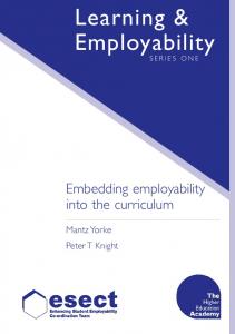
2. OO MODELING: GENERAL SOFTWARE VS DISCRETE EVENT SYSTEM Object-Oriented Modeling (OO Modeling) is technique in which a correspondence between a real-world object and a modeled object is established explicitly in a one-to-one manner. This section describes an overview of OO modeling in conjunction with DEVS formalism and UML methodology. 2.1 Overview of OO Modeling The origin of OO modeling concept is Simular67 developed by Nygaard & Dhal[10]. For the purpose of discrete event systems modeling, Simular67 proposed the concept of an object and an abstract data class. After that, a number of OO Modeling languages have been developed. UML is one such example, which is used not for discrete event modeling but for general software modeling. On the other hand, DEVS formalism supports a sound semantics for OO modeling of discrete event systems. Fig.1 shows difference between two OO modeling methodology. Origin of OO Prog. Lang Simular 67
Software Modeling
DEVS Formalism
UML Method
Math Framework For DES Modeling
OO Spec of Software
Execution of UML Spec
Execution of DEVS Spec
C++
DEVSim++ DEVS Simulation Engine
C++ library for DEVS simulation
Execution of Objects in time order
X : Input event set, finite set; S : State set, finite set; Y : Output event set, finite set; δint : S → S : internal transition ; δext : Q × X → S : external transition ; λ : S → Y : output function ; ta : S → Real where Q = {(s,e) | s∈S, 0≤e≤ta(s)} : total state of M
The first three elements in the 7-tuple are the system’s input, state set, and output, and the next four elements give the constraints among the three. A coupled model is a compound component consisting of atomic models and/or coupled models. The coupled model can itself be employed as a component in a larger coupled model, thereby giving rise to the construction of complex models with hierarchical structures. A coupled model is represented as follows. DN = < X,Y,M,EIC, EOC, IC>
OO Discrete Event Simulation Lang
DES Modeling
Within the formalism, one specifies a discrete event system in two kinds of models: atomic model and coupled model. An atomic model is an unbreakable component of a system, which is represented as follows. M = < X, Y, S, dext, dint, ta, l >
General Purpose Prog. Lang.
Execution of Objects in calling order
DES = Objects with time constraints
Figure 1. OO modeling: DES vs general software 2.2 UML: OO Modeling of General Software The Unified Modeling Language (UML)[3] is one of the most exciting tools in the world of object-oriented system development today. UML enables system builders to create blueprints that capture their visions in a standard, easy-tounderstand way and communicate them to others. Basically, UML models a system in multiple views each of which is represented by a corresponding graphical diagram. As a visual modeling language, UML employs 8 graphical diagrams: use case diagram, class diagram, object diagram, state diagram, activity diagram, sequence diagram, collaboration diagram and component diagram. 2.3 DEVS: OO Modeling of Discrete Event Software DEVS formalism is a framework for modeling of discrete event systems in a hierarchical, modular manner[2].
X : input event set , finite set ; Y : output event set , finite set ; M : internal model set, finite set ; EIC: EIC ⊆ DN.IN × ∪ M.IN : External Input Coupling ; EOC: EOC ⊆ ∪ M.OUT × DN.OUT : External Output Coupling ; IC: IC ⊆ ∪ M.OUT × ∪ M.IN :
Internal Coupling ;
Atomic models and coupled models are consists of the total system model by hierarchical structure. 3. PROPOSED DEVS MODELING PROCESS Section 3 proposes an employment of a UML subset as a means of intermediate representation of modeling objects which is understandable to both domain experts and M&S experts. As such UML plays a role of a front end of the DEVS modeling process. 3.1 OO Modeling Process in DEVS Framework The OO modeling process within the DEVS framework can be summarized in Fig. 2. Step 1: Identity objects as atomic and coupled models Step 2: For each atomic model Identify input, output and state (X, Y, S) Identify four characteristic functions (ta, δint , δext , λ)
Step 3: For each coupled model Identity input, output and components (X, Y, Mi) Identity three coupling relations (EIC, EOC, IC) Identify priority of components (sel)
Step 4: Implement each atomic model Step 5: Implement each coupled model
Figure 2. OO DEVS modeling process
Successful modeling using the process still requires deep knowledge about a system to be modeled as well as understanding of DEVS framework. Therefore, a domain expert provides functional requirement/specification of the modeled system. Domain experts may employ UML subsets for such specification as a preparation for DEVS modeling. 3.2 Embedded UML subset DEVS formalism specifies a system as a collection of objects each of which can be either atomic or coupled model. Each atomic model is a specification of an object with associated attributes and operations defined on them. A coupled model specification includes interactions between models which are components of the coupled model. Therefore it is not necessary to use all UML diagrams from which DEVS models are derived. More specifically, we employ three UML diagrams, namely use case diagram, class diagram and sequence diagram, for modeling of objects in a sense of general software[3]. The UML model is transformed into a DEVS model with additional information which is required for discrete event modeling. 3.2.1 Use Case Diagram A use case is description of system’s behavior from a user’s standpoint in an external view. For system developers, this is a valuable tool: it’s a tried-and-true technique for gathering system requirements from a user’s point of view. That’s important if the goal is to build a system that real people can use. 3.2.2 Class Diagram The class diagram is a central modeling technique that runs through nearly all object-oriented methods. This diagram describes the types of objects in the system and various kinds of static relationships which exist between them. There are three principal kinds of relationships which are important: associations (a customer may rent a number of videos), subtypes (a nurse is a kind of person) and aggregation (an engine is part of an aircraft). 3.2.3 Sequence Diagram A sequence diagrams is one of the five diagrams used in the UML for modeling the dynamic aspects of systems. A sequence diagram shows an interaction, consisting of a set of objects and their relationships. The diagram includes messages that may be dispatched among them with an emphasis on their time orderings. Graphically, a sequence diagram is a table that shows objects arranged along the X axis and messages, ordered in increasing time, along the Y axis. 3.3 Proposed Modeling Process Fig. 3 represents the proposed DEVS modeling process in which UML subsets are embedded at the front end.
UML Subset
Use case
System to be modeled
Domain Expert
Simulated Logic
Domain Expert
class
M&S Expert
DEVS Model
M&S Expert or Software Engineer
DEVS Simulator
sequence
Figure 3. Proposed modeling process The main objective of the front end is a means for common representation of objects and communication between domain experts and DEVS experts using such representation. 3.3.1 System Æ UML subset :Software Modeling Functional requirements of a system to be modeled can be expressed by a use case diagram from simulated logic via system analysis. The diagram can be obtained as the following steps. 1. Define actors from the simulated logic with modeling objectives considered. 2. Define scenarios as operations to be offered to actors. After constructing a use case diagram, system modeling can be divided into two parts: static and dynamic. The former is modeled by a class diagram and the latter by a sequence diagram. A class diagram offered by UML represents the types of objects and their attributes. But in this proposed modeling process, class diagram represents objects, functions, and hierarchical structure of their organization. The diagram can be constructed with the following steps. 1. Define classes with reference to the role of the system. 2. Classify the classes above by characteristic and similarity in the system. 3. Represent a hierarchical structure of the classes A sequence diagram represents interactions among objects in time order to exchange information. The objects are instances of classes in the class diagram. A sequence of the execution is defined by use case diagrams. Each sequence diagram reflects a corresponding use case. The sequence diagram can be constructed with the following steps. 1. Select one of use case diagrams. 2. Choose classes among class diagrams to execute the selected use case. 3. Define a sequence of interchanging messages. 4. If any, confirm time constraints from the simulated logic. 5. Repeat 1-4 to all use cases. 3.3.1 UML subset Æ DEVS models: DES Modeling After constructing sequence diagrams, transformation of UML diagrams into DEVS models completes discrete event modeling. To do so requires mapping of UML diagrams information into definition of atomic models and coupled models. Since sequence diagrams include all information of use case and class diagrams, information of sequence
diagrams is first transformed to the definition of DEVS models. Then, information that is not represented in UML but requires for DEVS models is added. Let us show transformation from UML subsets to DEVS information in the following 8 steps. 1. Identify atomic DEVS models from an instance of sequence diagrams. 2. Define input/output events of the atomic DEVS as shown in Fig. 4. M = < X, Y, S, δext, δint, ta, λ >
B.
Merge the start point of the sequence diagram and the end point of the sequence diagram to the initial state of the DEVS model. Sinital !selection
?Send(amount)
Sc_
!change
Sa‾
Sb_
Sc‾
Sd_
!amount
Register !selection
Send (amount)
[amount=price]
Se_
Select (Soda)
[Change not in Reserve]
Figure 7. Example of 4-B.
[amount>price]
Return amount [Change in Reserve] Return change
C.
[Change in Reserve] Select (Soda)
Translate all message sequence of the sequence diagram to state transition of the atomic models. If any, show the conditions together.
Figure 4. Input/output events extraction
Sinital
3. Define a state set. A state must include information of input/output events in a sequence diagram. As shown in Fig. 5 each state should be associated with both an external and an internal transitions in an atomic DEVS model.
?Send(amount)
Sa‾
Sc_
S_
δint : Q → Q
!output
[amount=price]
Sb_
!amount
[amount>price & Change not in Reserve]
[amount>price & Change in Reserve]
Qint : two state / an output
!selection
!change
Sc‾
Sd_ !selection
S‾
Se_
Figure 8. Example of 4-C.
Qext : two state / an input δext : Q * X Æ Q
S_
?input
S‾
D.
Minimize states if equivalent states exist.
Figure 5. Definition of state set Sinital
4. Define state transition between states obtained in 3. State transition can be obtained from sequence diagrams. All message exchanges on one activation of the sequence diagram can be described into one transition sequence. A. Show message transmission among defined states.
?Send(amount)
Sa‾
Sb_
!amount
Sc_
Sd_ !selection
!change
Se_
Sa_
?Send
Sa‾
Sb_
Sc_
!change
Sc‾
Sd_
!selection
Figure 9. Example of 4-D.
Sb‾
E.
!selection
[amount=price]
[amount>price & Change not in Reserve]
[amount>price & Change in Reserve]
Sinital
Se_
!selection
Se‾
Figure 6. Example of 4-A.
!amount
Sd‾
After the steps A~D, specification of time advance functions in atomic DEVS models are remained. If a special time constraints is defined in the sequence diagrams, show the condition in the confirmed state. If only an input causes the state transition from a state s, it can be describe by a passive state with ta(s)= ∞. If a state s’ describes only output events, then ta(s’)=0.
5. After 4, it is completed to describe an instance of sequence diagrams into an atomic model. Repeat A~E for all instances of sequence diagrams. 6. Repeat 1~5 for all sequence diagrams. 7. After 6, combine the atomic models from the same class, for each class describes a component of system. Requirement/ Specification
Sequence Diagram 1
a11
a12
Sequence Diagram 2
…
a21
a22
…
an1
an1
Concentration point/taxi
…
…
axx
a(12,n1)
4.1 UML Modeling of Requirement/Specification At first, the system is modeled in UML diagrams – use case diagram, class diagram and sequence diagram. Among these diagrams, class/sequence diagrams are shown in Fig.12.
Sequence Diagram n
…
X(12,n1) = X12∪Xn1, Y(12,n1) = Y12∪Yn1
1. Customer orders a taxi by calling a call taxi company. 2. Company contacts concentration points and dispatches a taxi to the customer. 3. The taxi rides the customer to a destination.
Concentration point
taxi
Managing Request Managing Taxi at concentration taxi
Location report
…
a(xx,xx)
Figure 10. Example of 7. 8. After 7, all atomic models are defined. We can draw information of the coupled model from atomic models and class diagram. This is because we represent class diagrams in a hierarchical form. For coupled modeling, we first identify components of a coupled model from class diagrams. Then, we identify external input/output coupling between the coupled model and components. Finally, we identify an internal coupling among atomic models.
Concentration Point
Driving taxi
Control center Customer location Taxi identification
success success
[if not] fail
fail
Customer location choose taxi and start
Add driving taxi success
4. CASE STUDY: CALL TAXI SYSTEM To demonstrate effectiveness of the proposed methodology, modeling and simulation of a concentration point/taxi simulator, a subsystem for a Call-Taxi system simulation as shown in Fig. 11, is exemplified. Customer
Control Center
Situation Monitor
HLA Network
Concentration point/ taxi
Figure 12. Class/Sequence diagram of system 4.2 UML to DEVS Transformation Using the proposed modeling process, UML subsets can be transformed to DEVS models. In the figure shown above, we define a Concentration point and a Driving taxi as atomic models. A state transition diagram of the Concentration point/Driving taxi atomic models from all sequence diagrams is shown in Fig 13 and 14. ?taxi
Control Center
Concentration point
No driving taxi ∞
if no driving taxi
!location !&return driving 1 sec ?location
!response
judgement 0
Figure 13. Atomic model of driving taxi
. Figure 11. Concentration point/taxi system Brief scenario of the system behavior is as follows.
The time advance of the driving state is described at the sequence diagram, but the others are not included in
UML subset. Thus, they must be obtained from functional requirements or otherwise defined at this stage. ?Initial
Initial ∞
Init. Res 0
[If fail]
Error ∞
[if success] ?connection test connection 0
?customer_location !start_response
!reponse
?Info_Taxi count 0
?customer_location &taxi_identification
!total_count
Number confirm 0
Location confirm 0
?request_num !number
?request_location
start 5sec
Location delivery 0
!location Wait. Res. ∞
Control ∞ !response delivery
Response delivery 0
?response
?return return 0
!location
Figure 14. Atomic model of concentration point Likewise, a coupled model can be constructed from class diagrams and sequence diagrams. Concentration point/taxi return From Control center
sequence diagram can specify only deterministic sequences of message between objects. However, discrete event modeling often requires specification of random sequences of message between models. Thus, a sequence diagram can not express an event occurrence at a random time. Future work may extend UML sequence diagram to express such a random sequence of message exchanges.
Taxi start Concentration Point location
taxi
Figure 15. Coupled model of system 4.3. Simulation Result From the above stage, we obtained a DEVS model of a concentration point/taxi system of Fig. 11, consisting of 2 atomic DEVS models. The overall DEVS model has been implemented using the DEVSimHLA environment[11], a HLA compliant simulation environment of DEVS models. We observed that simulation result is logically correct, thus proving the correctness of the proposed methodology.
5. CONCLUSION The paper proposed a DEVS modeling process in which UML subsets were embedded at a front end. An objective of the UML employment was to provide a means for OO modeling of systems understandable to both domain experts and M&S experts. A systematic method for transformation from UML to DEVS models was presented. A case study demonstrated effectiveness of the proposed approach. Our experience in a larger modeling project showed that embedding the UML subsets improved the effectiveness of the DEVS modeling process. The proposed approach has limitations which are inherited by UML expressive power for modeling discrete event systems. For example, a
Reference [1] Kenneth S. Rubin. 1997. Developing Object-Oriented Software – An Experience-Based Approach: Prentice Hall PTR [2] Bernard P. Zeigler; Herbert Praehofer; Tag Gon Kim. 2000. Theory of Modeling and Simulation. ACADEMIC PRESS [3] Joseph Schmuller. 2002. Teach Yourself UML in 24 Hours 2/E. SAMS [4] MuDer Jeng; WeiZhao Lu. 2002. “Extension of UML and Its Conversion to Petri Nets for Semiconductor Manufa-cturing Modeling” in Procs. IEEE International Conf-erence on ICRA’02 Robotics and Automation, Washington, DC USA, 5. pp. 3175-3180 vol.3 [5] A. Bondavalli; I. Majzik; I. Mura. 1999. “Automatic depe-ndability analysis for supporting design decisions in UML”, in Proc. 4th IEEE International Symposium on High-Assurance Systems Engineering, Washington, DC USA, 11. pp. 64-71 [6] A. Boccalatte; D. Giglio; M. Paolucci. 1999 “A Case tool for information system project and development”, in Procs. IEEE SMC ’99, Tokyo Japan, 10. pp.10421047 vol.3 [7] B. Bordbar; L. Giacomini; D.J Holding. 2000. “UML and Petri nets for design and analysis of distributed systems”, in Procs. the 2000 IEEE International on Control Applications, Anchorage, AK USA, 9. pp.610615 [8] H. Watanabe; H. Tokuoka; W. Wu, M. Saeki. 1998. “A technique for analyzing and testing object-oriented software using colored Petri nets”, in Proc. Asia Pacific Soft. Conf. Taipei, Taiwan, 12. pp. 182-190 [9] Hendrik Richter; Lothar Marz. 2000. “Toward a Standard Process: The Use of UML For Designing Simulation Models” in Procs. Simulation Conference, Orlando, FL USA, 12. pp. 394-398 vol. 1 [10] OJ Dahl; K Nygaard. 1966. “Simula - an algol-based simulation language” In Communications of the ACM, New York, NY USA, 9. Pages:671-678 vol 9. [11] Tag Gon Kim, “DEVSimHLA User’s Manual”, http://smslab.kaist.ac.kr/