field-programmable gate array (FPGA) whose basic cell is a multiplexer with ... D. Mange, E. Sanchez, A. Stauffer, and G. Tempesti are with the Logic. Systems Laboratory, Swiss .... allows a relatively simple manual computation [8], [9]. Beyond.
IEEE TRANSACTIONS ON VERY LARGE SCALE INTEGRATION (VLSI) SYSTEMS, VOL. 6, NO. 3, SEPTEMBER 1998
387
Embryonics: A New Methodology for Designing Field-Programmable Gate Arrays with Self-Repair and Self-Replicating Properties Daniel Mange, Member, IEEE, Eduardo Sanchez, Member, IEEE, Andr´e Stauffer, Member, IEEE, Gianluca Tempesti, Member, IEEE, Pierre Marchal, Member, IEEE, and Christian Piguet Abstract— The growth and the operation of all living beings are directed through the interpretation, in each of their cells, of a chemical program, the DNA string or genome. This process is the source of inspiration for the Embryonics (embryonic electronics) project, whose final objective is the conception of very large scale integrated circuits endowed with properties usually associated with the living world: self-repair (cicatrization) and self-replication. We will begin by showing that any logic system can be represented by an ordered binary decision diagram (OBDD), and then embedded into a fine-grained field-programmable gate array (FPGA) whose basic cell is a multiplexer with programmable connections. The cellular array thus obtained is perfectly homogeneous: the function of each cell is defined by a configuration (or gene) and all the genes in the array, each associated with a pair of coordinates, make up the blueprint (or genome) of the artificial organism. In the second part of the project, we add to the basic cell a memory and an interpreter to, respectively, store and decode the complete genome. The interpreter extracts from the genome the gene of a particular cell as a function of its position in the array (its coordinates) and thus determines the exact configuration of the relative multiplexer. The considerable redundancy introduced by the presence of a genome in each cell has significant advantages: self-replication (the automatic production of one or more copies of the original organism) and self-repair (the automatic repair of one or more faulty cells) become relatively simple operations. The multiplexer-based FPGA cell and the interpreter are finally embedded into an electronic module; an array of such modules make it possible to demonstrate self-repair and self-replication. Index Terms—Embryonic electronics, field-programmable gate arrays (FPGA’s), multiplexer-based FPGA’s, ordered binary decision diagrams, self-repairing FPGA’s, self-replicating FPGA’s.
I. INTRODUCTION A. Toward Embryonics HUMAN being consists of approximately 60 trillion 1012 ) cells. At each instant, in each of these 60 (60 trillion cells, the genome, a ribbon of 2 billion characters,
A
Manuscript received October 18, 1995; revised May 18, 1998. This work was supported by the Swiss National Science Foundation under Grants 2136’200.92 and 20-39’391.93. D. Mange, E. Sanchez, A. Stauffer, and G. Tempesti are with the Logic Systems Laboratory, Swiss Federal Institute of Technolgy, Lausanne CH 1015 Switzerland. P. Marchal and C. Piguet are with the Centre suisse d’´electronique et de microtechnique SA, Neuchˆatel CH 2007 Switzerland. Publisher Item Identifier S 1063-8210(98)05984-8.
is decoded to produce the proteins needed for the survival of the organism. This genome contains the ensemble of the genetic inheritance of the individual and, at the same time, the instructions for both the construction and the operation of the organism. The parallel execution of 60 trillion genomes in as many cells occurs ceaselessly from the conception to the death of the individual. Faults are rare and, in the majority of cases, successfully detected and repaired. This process is remarkable for its complexity and its precision. Moreover, it relies on completely discrete processes: the chemical structure of DNA (the chemical substrate of the genome) is a sequence of four bases, usually designated with the letters A (adenine), C (cytosine), G (guanine), and T (thymine). Our research is inspired by the basic processes of molecular biology [16]. By adopting certain features of cellular organization, and by transposing them to the two-dimensional (2-D) world of integrated circuits on silicon, we will show that properties unique to the living world, such as selfreplication and self-repair, can also be applied to artificial objects (integrated circuits). B. Objectives and Strategy Our final objective is the development of very large scale integrated (VLSI) circuits capable of self-repair and selfreplication. These two properties seem particularly desirable for complex artificial systems meant for hostile (nuclear plants) or inaccessible (space) environments. Self-replication allows the complete reconstruction of the original device in case of a major fault, while self-repair allows a partial reconstruction in case of a minor fault. Section II introduces the fundamental features of the Embryonics project (for embryonic electronics), which is based on a general hypothesis, defining the silicon environment in which the quasi-biological development occurs, and on three features, which roughly mimic the process of cellular development: multicellular organization, cellular differentiation, and cellular division. To represent and implement a given digital system on a FPGA we select, in Section III, an efficient and universal representation: the ordered binary decision diagram (OBDD). We will show that the use of such a representation greatly simplifies the realization of a new family of FPGA’s, based
1063–8210/98$10.00 1998 IEEE
388
IEEE TRANSACTIONS ON VERY LARGE SCALE INTEGRATION (VLSI) SYSTEMS, VOL. 6, NO. 3, SEPTEMBER 1998
on a fine-grained cell. This cell, called MUXTREE, contains essentially a multiplexer with one control variable and a nontrivial programmable connection network. Section IV describes in detail the MUXTREE cell, which in fact constitutes the application layer of the FPGA, and its 20 configuration bits. According to our biological approach, these 20 bits are the gene of the cell and all the genes of a given digital system are its genome. Section V introduces the two configuration layers which will perform the computation of the gene of each cell. The first layer computes the coordinates of a given cell from the coordinates of its neighbors. The second layer determines, from the complete genome and from the local coordinates of the cell, its gene. This is the equivalent of the process of cellular differentiation, and is implemented through the use a very simple binary decision machine, which we call NANOPASCALINE, charged with the execution of the GENOME program. Finally, Section VI briefly describes the realization of the cellular division process, that is, the duplication of the genome of a mother cell into one or two neighboring daughter cells. The final cell, made up of an application layer (MUXTREE) and two configuration layers (NANOPASCALINE), is finally embedded into a demonstration module: the BIODULE. Section VII shows that any given digital system implemented by an array of BIODULES is endowed with the properties of self-repair and self-replication. Section VIII illustrates the limitations of the current project and outlines the ongoing research, aimed at the development of an integrated circuit endowed with quasi-biological properties.
(a)
(b)
A. The General Hypothesis about the Environment
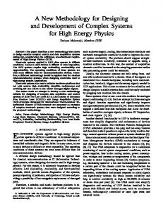
Fig. 1. The three features of embryonics applied to the example of an up–down counter. (a) Multicellular organization with a nine-gene genome. (b) Cellular differentiation with the complete genome in every cell and cellular division copying the genome of the mother cell into daughter cells (t1 1 1 1 t4: clock periods).
The general hypothesis describes the environment in which the quasi-biological development occurs. In the framework of electronics, it consists of a finite (but as large as desired) 2-D space of silicon, divided into rows and columns. The intersection of a row and a column defines a cell, and all cells have an identical structure, i.e., an identical network of connections and an identical set of logic operators. The physical space or cellular array is therefore homogeneous, that is, made up of absolutely identical cells: only the state of a cell can differentiate it from its neighbors.
its position (its coordinates ). Fig. 1(a) then shows the genome of the up–down counter, with the corresponding and vertical coordinates. Let then each horizontal cell contain the entire genome [Fig. 1(b)]: depending on its position in the array, each cell interprets the genome and extracts the gene which configures it. In summary, storing the whole genome in each cell makes this cell universal: it can realize any gene of the genome, given the proper coordinates.
B. First Feature: Multicellular Organization
D. Third Feature: Cellular Division
The first feature is that of multicellular organization: the artificial organism is divided into a finite number of cells [Fig. 1(a)], where each cell realizes a unique function, determined by a number called the gene of the cell. Fig. 1(a) illustrates the example of a simple artificial organism, an up–down counter, realized with nine cells, each cell being defined by a different gene (a five-digit hexadecimal number). The calculation of these genes will be analyzed in detail later.
At startup, the mother cell [Fig. 1(b)], arbitrarily defined as , holds the one and only copy having coordinates of the genome. At time , the genome of the mother cell is copied into the two neighboring (daughter) cells to the north and to the east. The process then continues until the 2-D space is completely programmed. In our example, the furthest cell is programmed at time .
II. THE FOUNDATIONS
OF
EMBRYONICS
C. Second Feature: Cellular Differentiation Let us call genome the set of all the genes of an artificial organism, where each gene is characterized by its value and
III. SYNTHESIS OF ORDERED BINARY DECISION DIAGRAMS (OBDD) To fit our demands, we needed to find a method capable of generating, starting from a set of specifications, the configu-
MANGE et al.: EMBRYIONICS: A NEW METHODOLOGY FOR DESIGNING FPGA’S
389
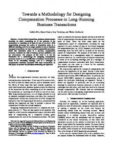
ration for a homogeneous network of cells, where each cell is defined by an identical architecture and a usually distinct function (gene). To meet our requirements, we have selected a particular representation: the ordered binary decision diagram (OBDD). This representation, with its well-known intrinsic properties such as canonicity [2], [4], was chosen for two main reasons [see, for example, Fig. 2(c)]: on one hand, it is a graphical representation which exploits well the 2-D space and immediately suggests a physical realization on silicon; on the other hand, its structure leads us to a natural decomposition into cells realizing a logic test (a diamond), easily implemented by a multiplexer. We will illustrate the handling of ordered binary decision diagrams through a simple example, an up–down counter. Our choice will lead us to define our new FPGA as a homogenous array where each cell contains a programmable multiplexer with one control variable, implementing precisely a logic test. Such an FPGA is said to be fine-grained.
(a)
A. Example of a Modulo-4 Up–Down Counter As an example, let us consider the realization of the abovementioned modulo-4 up–down counter, defined by the following sequences:
(b)
for (counting up); for (counting down)
(1)
This definition is equivalent to the two state tables of Fig. 2(a), and . defining the future states B. Ordered Binary Decision Trees and Diagrams We define a complete (or canonical) binary decision tree as branches corresponding to the a tree for variables having possible input states; for the tree of Fig. 2(b), representing , we have and . Each test element of the tree is represented by a diamond and defined by a test variable: it has a single input, a “true” output (test variable equal to “1”) and a “complemented” output (test variable equal to “0”), identified by a small circle. The leaf elements, represented as squares, define the output value of the given function ( in our example). In our case, the use of Karnaugh maps for simplifying is possible trees [8], [9] shows that no simplification of (Fig. 2(a): there is no block, i.e., no pattern formed by adjacent “0”’s or “1”’s). On the other hand, the Karnaugh map [Fig. 2(a)] reveals one block of four “0”’s and one for block of four “1”’s, which gives us to the minimal simplified and containing only two tree of Fig. 2(b), representing branches. A more detailed analysis of the Karnaugh maps of Fig. 2(a) reveals two types of blocks of blocks (ST0 and ST1), rep[Fig. 2(b)]. It can be resenting subtrees of the tree of is equal to the observed, moreover, that the function . subtree
(c)
(d) Fig. 2. Modulo-4 up–down counter. (a) State table (Karnaugh map). (b) Canonic ( 1+) and minimal ( 0+) binary decision trees. (c) Ordered binary decision diagrams for 1+ and 0+. (d) Multiplexer implementation of the OBDD’s.
Q
Q
Q Q
The sharing of identical subtrees implies the convergence of branches of the tree and its transformation into a new representation: the binary decision diagram (BDD). Finally,
390
IEEE TRANSACTIONS ON VERY LARGE SCALE INTEGRATION (VLSI) SYSTEMS, VOL. 6, NO. 3, SEPTEMBER 1998
the sharing of a subtree (ST0) belonging to the two functions and and the permutation of the “0” and “1” outputs of certain diamonds lead us to the final diagram of Fig. 2(c), which represents a forest of binary decision diagrams. In the above discussion, we have implied that the binary decision diagrams and trees were ordered, that is, characterized at the lower by a fixed position for the test variables: at the middle level, and at the upper level. Using level, Bryant’s notation [4], we will write (2) It can be observed that all logic systems, combinational or sequential, of variables will require a cellular network of rows. On the other hand, the minimal number of columns will depend on the simplification method adopted to obtain the ordered binary decision diagrams from the original specifications. For problems of up to six variables, the Karnaugh map allows a relatively simple manual computation [8], [9]. Beyond six variables, more complex analytical methods require the use of a computer [4], [5]. C. Hardware Implementation Our design decision has been to implement directly the ordered binary decision diagrams on silicon, and to build our fine-grained basic cell around a test element (a diamond). Such an implementation is possible if one replaces each test element with a 2-to-1 multiplexer, keeps the same interconnection diagram, and assigns the values of the leaf elements to the corresponding multiplexer inputs [8]. Fig. 2(d) shows the direct multiplexer implementation of the up–down counter. and are available at The two state functions the outputs of the top multiplexers: the ordered diagrams of Fig. 2(c) are read bottom-up in Fig. 2(d). IV. A NEW FIELD-PROGRAMMABLE GATE ARRAY BASED ON A MULTIPLEXER CELL A. General Remarks A simple examination of Fig. 2(d) allows us to identify the main features of the programmable cell, henceforth referred to as MUXTREE (for multiplexer tree). • Each of the two inputs of the multiplexer (labeled “0” and “1”) will be programmable. The input will be either a logic constant (“0” or “1”) or the output of the multiplexer of one of the neighboring cells to the south, southeast, or southwest. • The output of the multiplexer will be, therefore, connected to the inputs of the multiplexers in the neighboring cells to the north, northeast, and northwest. • The realization of sequential systems requires the presence, in each cell, of a synchronous memory element, a -type flip-flop, which will allow, in our example, to and (instead of obtain directly the values and ) needed for the display and for the retroaction of the secondary variables. • Long-distance connections are necessary to connect a cell to any other cell in the array. In our example, the
variable (itself obtained at the output of the mentioned flip-flop) must be brought back to the inputs of the multiplexers of the middle row of cells. This type of connection demands a system of universal buses, running through the entire array. In brief, the heart of the cell remains the 2-to-1 multiplexer, optionally followed by a flip-flop. Inputs and outputs are programmable and can be connected either to immediate neighbors, according to a topology proper to binary decision diagrams (where information flows from the bottom to the top), or to faraway cells through a network of perfectly symmetric universal buses. To facilitate the detailed description of the MUXTREE cell, we will separate it into two levels: the logic level, that is, the basic multiplexer and its immediate connections, and the connection level, that is, the bus network for faraway connections. B. Description of the Logic Level The MUXTREE cell (Fig. 3) is based on a 2-to-1 multiplexer (in the lower part of the test block TB) and a -type flip-flop (in the memory block MB) for clocked sequential behavior. Connections to the inputs of the main multiplexer are defined using the 8-to-1 multiplexers of the connection block CB. The 6 bits LEFT2:0 and RIGHT2:0 select one out of eight inputs for the left and right branches of the main multiplexer. The second 2-to-1 multiplexer of TB selects one of the east buses (EOBUS, EIBUS) to control the main multiplexer. The 2-to-1 multiplexer of the output block OB allows the connection of the output of the main multiplexer or the output of the flip-flop to the north output (NOUT). A switch block SB, described in Section IV-C, provides interconnections between the input buses (NIBUS, EIBUS, SIBUS, WIBUS), as well as the output NOUT, and the output buses (NOBUS, EOBUS, SOBUS, WOBUS). Finally, the field-program bit REG (Fig. 3) controls the combinational or sequential behavior of the cell, while the field-program bit PRESET determines if an action on the INIT signal implies an asynchronous set or reset of the flip-flop. C. Description of the Bus Level and Global Representation In order to implement long connections, the bus network includes one switch block SB per cell. Fig. 4(a) symbolizes the interconnection possibilities between the four input and four output oriented buses. All connections are possible, with the exception only of “U-turns.” Fig. 4(b) shows the internal realization of the block. This realization, which also allows the north output (NOUT) to be connected to the four output buses, is realized using four 4-to-1 multiplexers. Each multiplexer is controlled by two field-program bits selecting one of the four possible inputs (the other directions input buses and the north output NOUT). Fig. 11(b) summarizes the input and output signals of the MUXTREE cell. In order to facilitate the hexadecimal representation of its gene, the 17 field-program bits of the cell are organized as a 20-bit data GENE19:0 (Fig. 3).
MANGE et al.: EMBRYIONICS: A NEW METHODOLOGY FOR DESIGNING FPGA’S
391
(a)
(b) Fig. 3. MUXTREE cell. (a) Detailed architecture (the switch block SB is described in Fig. 4). (b) The 20-bit data GENE19:0 with P R REG, and EB EBUS.
=
=
D. Application: Modulo-4 Up–Down Counter It can be immediately seen that the counter described by the ordered decision diagrams of Fig. 2(c) can be realized using an array of three lines and three columns (that is, by a total of nine MUXTREE cells). Fig. 2(c) is modified and leads to the final diagram [Fig. 5(a)] where we have the following: • the use of two -type flip-flops, symbolized with a square around the corresponding diamonds, generates the and in place of and ; variables • a cell is completely unused, while another cell is used ). exclusively as a direct connection (transmission of Using the bus level notation defined in a detailed description of the MUXTREE cell [11], we can then draw the connection layout of the counter [Fig. 5(b)]. Combining the information of Fig. 5(a) and (b) allows us to compute manually the 17 control bits of each gene, according to the format defined in Fig. 3, and finally produces
=
PRESET,
the genome of Fig. 1(a). For all indifferent conditions ( conditions), the corresponding bits were set to “0.”
E. Conclusion Thanks to the conception of the new family of fieldprogrammable gate arrays (FPGA’s) MUXTREE, we are currently able to realize any given logic system using a completely homogeneous cellular network. This realization is simplified by the direct mapping of the ordered binary decision diagrams onto the array. Thus, we have satisfied the general hypothesis on the environment described in Section II-A, as well as the first feature of the Embryonics project, that is, multicellular organization [Section II-B and Fig. 1(a)]. The manual computation of the genes can be very awkward. Two software tools (running on an Apple Macintosh) have been devised to overcome this problem. The first is a graphical editor, capable of determining the individual 20-bit genes for the MUXTREE implementation of any given function
392
IEEE TRANSACTIONS ON VERY LARGE SCALE INTEGRATION (VLSI) SYSTEMS, VOL. 6, NO. 3, SEPTEMBER 1998
(a)
Fig. 6. Hierarchical overview of the three layers and the corresponding block schemes of the final embryonic cell.
(b) Fig. 4. The switch block SB. (a) Interconnection possibilities. (b) Detailed architecture.
represented by an OBDD. The second is a numerical simulator, allowing the functional verification of the implementation. To this date, two physical realizations of arrays of MUXTREE cells have been implemented. The first consists of 20 programmable ACTEL 1020A circuits, realizing a homogecells. The second, neous surface of realized in collaboration with the CMP-Grenoble (Circuits multi projets, Prof. B. Courtois), is an integrated circuit cells. The chip was MUXCHIP consisting of fabricated at an SGS-Thomson Microelectronics facility [6]. V. CELLULAR DIFFERENTIATION: GENOME INTERPRETATION A. A Hierarchical Overview
(a)
(b) Fig. 5. Nine-cell implementation of the up–down counter. (a) Logic level and (b) bus level.
Rather than describing our final cell as a whole, we will, for the sake of simplicity, decompose it in three components or layers (Fig. 6) and describe each of these layers separately. The top layer is used to compute the local coordinates of the cell, usually by adding 1 to the coordinate of the of the southern western neighbor and to the coordinate neighbor. The middle layer contains a random access memory (RAM) and is used to store the entire genome: the memory stores a single gene per address, i.e., per pair of coordinates . Finally, the selected gene controls the bottom layer, which contains the functional cell (i.e., the MUXTREE cell defined in the preceding section). During normal operation, the top (address computation) and middle (genome) layers are fixed and the values they compute coordinates, gene GENE19:0) are constant. We ( and will say that these two layers, which are in fact configuration layers, are idle during operation. Modifications can only be effected at initialization (programming of the FPGA) or during the self-repair and self-replication processes. On the other hand, the bottom layer is the operational part or application layer. Its values usually change with time.
MANGE et al.: EMBRYIONICS: A NEW METHODOLOGY FOR DESIGNING FPGA’S
393
(a)
(b)
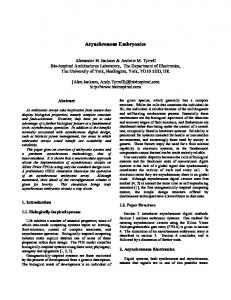
(c) Fig. 7. Computation and genome representation. (a) Gene computation, (b)
B. Microprogrammed Realization In all living beings, the genome is executed sequentially by a chemical processor, the ribosome. Drawing inspiration from this biological process, we will use a microprogram to compute the local coordinates and and to extract from our artificial genome, as a function of the coordinates, the gene GENE19:0. The artificial genome [for our example, that of the up–down counter of Fig. 1(a)] can be considered as a truth table (or look-up table) whose input states are the coordinates or and , and whose output states are the genes addresses GENE19:0. If we express the values of the coordinates and in pure binary code, using the logic variables and , we may apply the traditional simplification methods for binary decision trees [8], [9], and we finally obtain the
X coordinate computation, and (c) up–down counter genome. structured subprogram GENE of Fig. 7(a), represented symbolically in the program of Fig. 7(c). Assuming that the mother cell has coordinates we observe the following (Fig. 6): as a • each cell computes its horizontal coordinate of its western function of the horizontal coordinate neighbor; • each cell computes its vertical coordinate as a function of its southern neighbor; of the vertical coordinate is incremented • the sequence of horizontal coordinates by the and limited to a cycle width of the cellular array; • the sequence of vertical coordinates is incremented and by the height limited to a cycle of the cellular array.
394
IEEE TRANSACTIONS ON VERY LARGE SCALE INTEGRATION (VLSI) SYSTEMS, VOL. 6, NO. 3, SEPTEMBER 1998
We can then write two subprograms realizing the expressions mod mod
(3) (4)
in the example of the up–down counter where [Fig. 1(a)]. in pure If we express the coordinates and and , binary code, using the logic variables the simplification of the binary decision tree generates the structured subprogram of Fig. 7(b). An identical computation coordinate described can be performed on the by (4). [Fig. 7(a)] and the Merging the subprogram GENE as two subprograms which implement the increment of as in (4) generates the final structured in (3) and of microprogram or genome for the example of the up–down counter [Fig. 7(c)].
(a)
C. NANOPASCAL: A High-Level Language for Structured Microprogramming We will now define a programming language particularly well suited for the description, the interpretation and the duplication of the genome. This language, called NANOPASCAL for historical reasons, consists in fact of an absolutely minimal subset of the MODULA-2 language [15]. The NANOPASCAL language is described by the syntactic diagram of Fig. 8(a), where we can count seven distinct terminal symbols (ovals), which make up the instructions of the language (5) The pseudo-instruction begin is in fact never executed, and simply indicates the start of the program. The instruction end forces an unconditional jump to address “0” (this is in fact the only jump implemented by the language). The NOP (No operation) instruction represents the execution of a neutral realizes the synchronous operation. The assignment do OUT of a constant OUT in a register REG transfer REG of address . Since no jumps are allowed by the language, all of the instructions making up the conditional construct if then else (where is a test variable and and are or depends assignments) are read, and the execution of on the value of a signal EXEC (for EXECUTE) which, in turn, depends on the preceding values of the test variable . As an example, Fig. 8(b) shows the shape of the mnemonic program GENOME, realizing choosen parts of the final microprogram [Fig. 7(a) and (b)] in the syntax of the NANOPASCAL language. Writing the microprogram for a relatively large genome can be a bothersome endeavor. Therefore, we have developed two software tools which successively allow the following: • the compilation, starting from the truth table of the genome (Fig. 1(a), for example), of the complete NANOPASCAL mnemonic program, including the and addresses [Fig. 8(b)]; computation of the
(b) Fig. 8. NANOPASCAL language. (a) Syntactic diagram and (b) microprogram GENOME.
• the translation of the above-mentioned mnemonic program into a binary program directly executable by the interpreter (Section V-D).
D. NANOPASCALINE: An Interpreter for the NANOPASCAL Language Fig. 9(a) suggests a possible format and operating code (OPC) for the six types of executable instructions of the NANOPASCAL language defined in (5). These six types of instruction are executed by a binary decision machine or interpreter of the NANOPASCAL language (NANOPASCALINE). It consists mainly of the following elements [Fig. 9(a)]. • A program memory RAM of 256 words of 8 bits. • An address counter (CNT), whose output is the memory address ADR; ADR is incremented at each clock period (there are no jumps, with the exception of the instruction
MANGE et al.: EMBRYIONICS: A NEW METHODOLOGY FOR DESIGNING FPGA’S
395
(a)
(b) Fig. 9. NANOPASCALINE: NANOPASCAL interpreter. (a) Detailed architecture with format and operation code (OPC) for the six instructions of the language. (b) Stack operation table.
end which assures the jump to the address ADR 0 1). through the signal SYNCLR : • Eight assignment registers of 4 bits each ( : coordinates ; : display). GENE19:0; The selection of one register out of eight is made by a demultiplexer DMUX and will only be effective if both the following two conditions are met: 1) an instruction
do (signal DO=1) is being decoded and 2) the order of execution EXEC=1 is set. This last signal is crucial, and its value depends on the sequence of values of the test variable : the computation of the value of EXEC is performed by the stack STK described below. • A stack STK of eight levels of 1 bit for the computation of the signal EXEC. If we call STK[1] the variable of the
396
IEEE TRANSACTIONS ON VERY LARGE SCALE INTEGRATION (VLSI) SYSTEMS, VOL. 6, NO. 3, SEPTEMBER 1998
top level of the stack, and STK[2, ,8] the values of the levels below, then the table of Fig. 9(b) describes the global operation of the stack. The logic product EXEC
STK STK
STK STK
STK STK
STK
STK (6)
which controls the execution of the assignment instrucOUT depends therefore on the succestions do REG sion of values of the test variable . • A multiplexer MUX which selects one out of 16 test variable . • A decoder DEC, controlled by the five bits of the operating code OPC4:0, which will generate the signals controlling the address counter CNT (signal END), the demultiplexer DMUX (signal DO) and the STK (signals IF, ELSE, and ENDIF). In conclusion, our NANOPASCALINE is limited to the computation of artificial organisms composed of at most MUXTREE cells.
(a)
E. Conclusion Our choice for the execution of the NANOPASCAL language is thus the following: the interpreter executes linearly all the instructions of the microprogram by incrementing the address ADR of the memory. The synchronous assignments OUT are executed only if the signal EXEC, generated REG by the stack, is one. This choice provides two main advantages: • the time of execution of the microprogram GENOME is constant and the same for all the cells; • the duplication of the microprogram of a mother cell into an daughter cell can be executed in parallel with its interpretation (cellular division). The time of execution of such a program is obviously greater than that of an equivalent program with jumps. This drawback is less important in our case, since the GENOME microprogram is active only during the configuration of the FPGA, and not during its operation.
VI. CELLULAR DIVISION: DUPLICATION OF THE GENOME The duplication of the GENOME microprogram is accomplished automatically, in parallel with its interpretation. A register, controlled by the configuration clock CCK, is associated with the RAM in the NANOPASCALINE interpreter of each cell. At each rising edge of CCK, an instruction of the GENOME microprogram is copied into the cell through one of the SDATA or WDATA inputs selected by a physical jumper, manually set before start-up [Fig. 11(b)]. The copy of the instruction is then available on both of the NDATA and EDATA outputs. The GENOME microprogram is thus duplicated in permanence, resulting in a great simplicity of wiring and an excellent reliability, since an eventual transient fault (copy error) during a cycle will be corrected in the next cycle.
(b) Fig. 10. Properties of the up–down counter. (a) Self-replication and (b) self-repair.
In the symbol of the NANOPASCALINE interpreter 1 characterizes a faulty cell. [Fig. 11(b)], KO VII. SELF-REPLICATION
AND
SELF-REPAIR PROPERTIES
A. Self-Replication The self-replication of an artificial organism, for example the up–down counter of Fig. 1(a), rests on two hypotheses: 1) there exists a sufficient number of spare cells (unused cells at the right hand side of the array, at least three columns of three cells for our example) and 2) the calculation of the coordinates in Fig. 7(b)]. produces a cycle [ As the same pattern of coordinates produces the same pattern of genes, self-replication can be easily accomplished if the microprogram GENOME, associated to the homogeneous network of cells, produces several occurrences of the basic and/or pattern of coordinates [ in Fig. 1(a)]. In our example, the repetition of the horizontal coordinate pattern, i.e., the production of the pattern [Fig. 10(a)], produces one copy, the daughter automaton, of the original or mother automaton. Given a sufficiently large space, the self-replication process can be repeated for any number of specimens, both
MANGE et al.: EMBRYIONICS: A NEW METHODOLOGY FOR DESIGNING FPGA’S
397
B. Self-Repair
(a)
Even if our long-term objective is the development of very large scale integrated circuits, we have started by realizing a demonstration system, based on artificial digital cells called BIODULES [Fig. 11(a)]. In this context, the existence of a fault is decided by the human user by pressing the KILL button of a cell. Therefore, fault detection and fault location, two features which will be indispensable in the final system, where they will be implemented using BIST (builtin self-test) techniques [1], [11]–[13], are not present in the BIODULES. To implement self-repair, we have chosen, favoring simplicity, the following process [Figs. 10(b) and 11(a)]: • pressing the KILL button identifies the faulty cell; • the entire column to which the faulty cell belongs is considered faulty, and is deactivated (column in Fig. 10(b) in the example of the up–down counter); • all the functions of the application layer (MUXTREE) and of the configuration layers (NANOPASCALINE) of the column are shifted by one column to the right. Obviously, this process requires as many spare columns, to the right of the array, as there are columns to repair [one spare column in the example of Fig. 10(b)]. It also implies some modifications to the application and configuration layers, so as to add the capability of jumping the faulty column and shifting to the right all or part of the original cellular array [Fig. 11(b)]. Finally, it should be mentioned that the final BIODULE [Fig. 11(a)] also realizes the series-parallel conversion of the at the input, and data (DATA) and of the coordinates the opposite conversion at the output. This conversion minimizes the number of connections between each BIODULE. VIII. CONCLUSION A. Results
(b) Fig. 11. BIODULE: demonstration artificial digital cell. (a) The front panel and (b) detailed architecture.
in the and the axes. For a given cell, the dimensions of the artificial organism are limited in the first place by the and , that is, coordinate space ( at most 256 cells in our implementation), and then by the dimensions of the RAM which will contain the GENOME microprogram (256 words of 8 bits in our case).
The first result of our research is the development of a new family of FPGA’s called MUXTREE and based on a fine-grained cell containing a multiplexer with one control variable. The original features of this FPGA are essentially the following: • a completely homogenous organization of the cellular array; • an integration of the routing into each cell, both for the short- and long-distance (bus) connections; • a cell architecture allowing the direct mapping of binary decision diagrams onto the array. The FPGA satisfies both the general hypothesis (Section IIA) and the first feature of the Embryonics project, that of multicellular organization (Section II-B). Two physical implementations have been realized: a prototype array of 240 cells, itself implemented using FPGA’s of the ACTEL family, and a complementary metal–oxide–semiconductor (CMOS) integrated circuit containing 64 cells. The second result is the realization of a quasi-biological cell based on an application layer (the MUXTREE cell) and two configuration layers computing, as a function of the local
398
IEEE TRANSACTIONS ON VERY LARGE SCALE INTEGRATION (VLSI) SYSTEMS, VOL. 6, NO. 3, SEPTEMBER 1998
coordinates and of the genome, the specific gene controlling the application layer MUXTREE. The configuration layers are realized using a binary decision machine called NANOPASCALINE, which interprets the GENOME microprogram. The three layers of application and of configuration are finally embedded into a complete cell, implemented using an FPGA and a RAM, and then built as a demonstration module called BIODULE. We then show that an array of BIODULES satisfies the second and third features of the Embryonics project (Sections II-C and -D: cellular differentiation and division) and that it is endowed with the properties of self-replication and self-repair. The interest of self-repair is immediately obvious, as this property allows the repair of isolated faults, for example, the fault of a single cell. The importance of self-replication is less evident, and can be justified by the following: • the complete reconstruction of a device, in case of massive faults; • the automatic realization of homogeneous 2-D cellular automata, by repetition of the same basic cell; • the simplicity of moving a device in the cellular array by the simple alteration of the coordinates of the mother cell. B. Future Perspectives The main drawback of the BIODULE cell is the lack of balance between the application layer (MUXTREE), which realizes the universal function with a single variable, and the configuration layers (NANOPASCALINE), which store and interpret a rather complex microprogram. The development of a new coarse-grained FPGA cell will aim at correcting this imbalance [11]. The second drawback of the BIODULE, which is primarily a demonstration system, is the absence of a system for the detection and location of faults. While such a system could be implemented using relatively wellknown techniques, we are trying to exploit the peculiar features of FPGA’s (homogeneous cellular organization, possibility of reconfiguration) to obtain a BIST realization capable of being embodied into the integrated circuit which will finally have to possess all the computational power of an array of BIODULES [1], [11]–[13]. C. Historical and Theoretical Perspectives The early history of the theory of self-replicating machines is basically the history of John von Neumann’s thinking on the matter [7], [14]. Von Neumann’s automaton is in accord with the general hypothesis outlined in Section II-A, as each of its elements is a finite state machine with 29 states. In his historic work [14], von Neumann successively showed that a possible configuration (a set of elements in a given state) of his automaton can implement a universal constructor endowed with the three following properties: constructional universality, self-replication of the universal constructor and self-replication of a universal calculator. In biology, the cell is the smallest part of a living being containing the complete blueprint of the being, the genome. On the basis of this definition, it can be shown that von Neumann’s automaton is a unicellular organism, since it contains a single copy of
the genome, i.e., the description of the universal constructor and computer [11]. Each element of the automaton is thus a part of the cell, or, in biological terms, a molecule. Von Neumann’s automaton, therefore, is a molecular automaton, and universal construction and self-replication are complex processes, as they are caused by the interaction of thousands of elements, the molecules, each one realized by a finite state machine with 29 states. Arbib [3] was the first to suggest a truly “cellular” automaton, in which every cell contains a complete copy of the genome, and a hierarchical organization, where each cell is itself decomposed into smaller and regular parts, the “molecules.” Following this concept, the automaton we propose is a multicellular organism, as each of its elements contains a copy of the genome [nine copies in the case of the up–down counter of Fig. 1(a)]. Each element of our automaton is thus a cell in the biological sense, and our automaton is truly a multicellular automaton. Self-replication and self-repair are straightforward processes, as the BIODULE cell has been conceived especially to carry out globally the operations of cellular differentiation and division. The property of universal computation, that is, the possibility of realizing, repairing, and replicating a universal Turing machine, can theoretically be verified with the BIODULE cell. But the implementation of such a machine will be strongly simplified by the creation of a second generation of cells, coarse-grained [10]. The property of universal construction poses problems of a different nature, since it requires (always according to von Neumann) that BIODULE cells be able to implement artificial organisms of any dimension. The finite dimensions of our cells (memories, registers, etc.) are, for the moment, preventing us from meeting this requirement, a challenge which remains one of our main concerns and which could be solved, according to Arbib’s suggestion, by decomposing a cell into molecules. REFERENCES [1] M. Abramovici and C. Stroud, “No-overhead BIST for FPGA’s,” in Proc. 1st IEEE Int. On-Line Testing Workshop, July 1995, pp. 90–92. [2] S. B. Akers, “Binary decision diagrams,” IEEE Trans. Comput., vol. C-27, pp. 509–516, June 1978. [3] M. A. Arbib, Theories of Abstract Automata. Englewood Cliffs, NJ: Prentice Hall, 1969. [4] R. E. Bryant, “Symbolic boolean manipulation with ordered binarydecision diagrams,” ACM Computing Surveys, vol. 24, no. 3, pp. 293–318, 1992. [5] M. Davio, J.-P. Deschamps, and A. Thayse, Digital Systems with Algorithm Implementation. New York: Wiley, 1983. [6] S. Durand, “Muxchip,” Logic Syst. Lab., Swiss Federal Inst. Technol., Lausanne, Switzerland, Tech. Rep., Oct. 1994. [7] R. A. Freitas and W. P. Gilbreath, Eds., “Advanced automation for space missions,” in Proc. Nasa Conf., no. 2255, 1982. [8] D. Mange, Microprogrammed Systems: An Introduction to Firmware Theory. London, U.K.: Chapman and Hall, 1992. [9] D. Mange, “Teaching firmware as a bridge between hardware and software,” IEEE Trans. Educ., vol. 36, pp. 152–157, Mar. 1993. [10] D. Mange, D. Madon, A. Stauffer, and G. Tempesti, “Von Neumann revisited: A turing machine with self-repair and self-replication properties,” Robot. Autonomous Syst., vol. 22, no. 1, pp. 35–58, 1997. [11] D. Mange and M. Tomassini, Eds., Bio-Inspired Computing Machines. Lausanne, Switzerland: Polytechniques et Universitaires Romandes Press, 1998. [12] E. J. McCluskey, Logic Design Principles with Emphasis on Testable Semicustom Circuits. Englewood Cliffs, NJ: Prentice Hall, 1986.
MANGE et al.: EMBRYIONICS: A NEW METHODOLOGY FOR DESIGNING FPGA’S
[13] G. Tempesti, D. Mange, and A. Stauffer, “A robust multiplexer-based FPGA inspired by biological systems,” J. Syst. Architecture, vol. 43, no. 10, pp. 719–733, 1997. [14] J. von Neumann, Theory of Self-Reproducing Automata. Urbana, IL: University of Illinois Press, 1966. [15] N. Wirth, Programming in MODULA-2, 2nd ed. Berlin, Germany: Springer-Verlag, 1983. [16] L. Wolpert, The Triumph of the Embryo. New York: Oxford University Press, 1991.
Daniel Mange (M’94) received the M.S. and Ph.D. degrees from the Swiss Federal Institute of Technology, Lausanne, Switzerland. Since 1969, he has been a Professor at the Swiss Federal Institute of Technology. He held a position as Visiting Professor at the Center for Reliable Computing, Stanford University, Stanford, CA, in 1987. He is currently Director of the Logic Systems Laboratory, Swiss Federal Institute of Technology, and his chief interests include firmware theory (equivalence and transformation between hardwired systems and programs), cellular automata, artificial life, and embryonics (embryonic electronics).
Eduardo Sanchez (M’84) received the Diploma in electrical engineering from the Universidad del Valle, Cali, Colombia, and the Ph.D. degree from the Swiss Federal Institute of Technology, Lausanne, Switzerland. He is Professor of Computer Science in the Logic Systems Laboratory, Swiss Federal Institute of Technology, where he is engaged in teaching and research. His chief interests include computer architecture, VLIW processors, reconfigurable logic, and evolvable hardware.
Andr´e Stauffer (S’68–M’69) received the Diploma in electrical engineering and the Ph.D. degree from the Swiss Federal Institute of Technology, Lausanne, Switzerland. He spent one year as a Visiting Scientist at the IBM T. J. Watson Research Center, Yorktown Heights, NY, in 1986. He is a Senior Lecturer in the Department of Computer Science at the Swiss Federal Institute of Technology. In addition to digital design, his research interests include circuit reconfiguration and bio-inspired systems.
399
Gianluca Tempesti (M’95) received the B.S.E. degree in computer engineering from Princeton University, Princeton, NJ, in 1991 and the M.S.E. degree from the University of Michigan, Ann Arbor, in 1993. Since 1994, he has been working as a Teaching and Research Assistant at the Logic Systems Laboratory in the Department of Computer Science, Swiss Federal Institute of Technology, Lausanne, Switzerland. His research interests include self-test and self-repair, programmable logic circuits, processor design, and parallel computer architecture.
Pierre Marchal (M’94) received the M.S. degree in computer science from the University of Grenoble, France, in 1980 and the Ph.D. degree in computer science from the Institut National Polytechnique, Grenoble, France, in 1983. He joined the Microcomputing Laboratory of the Swiss Federal Institute of Technology, Lausanne, Switzerland, in 1987 and the Advanced Microelectronics Division of the CSEM Centre Suisse d’Electronique et de Microtechnique S.A., Neuchˆatel, Switzerland, in 1991. He is presently involved in the design of low-power circuits, reconfigurable architectures, self-structuring circuits, and on-line arithmetics.
Christian Piguet received the M.S. and Ph.D. degrees in electrical engineering from the Swiss Federal Institute of Technology, Lausanne, Switzerland. He is Head of the Ultra-Low-Power Sector at the CSEM Centre Suisse d’Electronique et de Microtechnique S.A., Neuchˆatel, Switzerland. His main interests include the design of very low-power microprocessors, low-power standard cell libraries, gated-clock and low-power techniques, as well as asynchronous design.