Min Li, Joe Nuebel, James L. Drewniak, Member, IEEE, Todd H. Hubing, Senior ... Richard E. DuBroff, Senior Member, IEEE, and Thomas P. Van Doren, Senior ...
IEEE TRANSACTIONS ON ELECTROMAGNETIC COMPATIBILITY, VOL. 42, NO. 2, MAY 2000
135
EMI Reduction from Airflow Aperture Arrays Using Dual-Perforated Screens and Loss Min Li, Joe Nuebel, James L. Drewniak, Member, IEEE, Todd H. Hubing, Senior Member, IEEE, Richard E. DuBroff, Senior Member, IEEE, and Thomas P. Van Doren, Senior Member, IEEE
Abstract—Airflow perforations in shielding enclosures can act as apertures facilitating the coupling from internal sources to external electromagnetic interference (EMI). This EMI radiation for single- and dual-screen configurations was studied herein experimentally and with finite-difference time-domain (FDTD) modeling. A general EMI reduction of more than 20 dB was achieved for dual-perforated screens spaced 1 cm apart when compared to EMI for a single perforated screen. However, in the dual-screen case, the space between the screens can act as a thin cavity, which, in turn, can lead to significant radiation at distinct angles. Damping the resonances by loading the space between the screens with lossy material mitigates this problem and achieves more than 20-dB reduction over a single screen. Index Terms—Aperture, FDTD, shielding enclosure.
I. INTRODUCTION
T
HE integrity of shielding enclosures is compromised by slots, seams, and apertures for heat dissipation. Radiation from unintended slots and apertures can usually be minimized with gasketing, however, it is more difficult to mitigate the radiation from intended apertures such as those designed for heat dissipation and airflow. Enclosures for high-speed digital designs use aperture arrays or perforated screens instead of large apertures for airflow and heat dissipation to minimize electromagnetic interference (EMI), while allowing for adequate air flow. Due to the total open area required for heat dissipation, as well as structural and manufacturing reasons, there is a lower bound on the minimum size of the apertures of the perforated screen. Considerable work has been done in the study of EMI coupling from perforated aperture arrays [1]–[6]. The radiation from a perforated screen with a large number of apertures and reasonable aperture size may result in EMI problems at high frequencies, i.e., above the fundamental cavity resonance, even though the aperture size might be electrically small. One approach to minimize this risk is to utilize a honeycomb configuration instead of a perforated screen. The honeycomb configuration works well but adds considerable cost to the design over a perforated screen. A dual-perforated screen was tested here as a means of further reducing EMI over a single perforated screen. Manuscript received January 8, 1998; revised January 18, 2000. This work was supported by the University of Missouri-Rolla EMC Consortium. M. Li was with the University of Missouri-Rolla, Rolla, MO 65409–02499 USA. She is now with Lucent Technologies, Engineering Research Center, Princeton, NJ 08542 USA. J. Nuebel is with Sun Microsystems, Palo Alto, CA 94303 USA. J. L. Drewniak, T. H. Hubing, R. E. DuBroff, and T. P. Van Doren are with the Department of Electrical Engineering, University of Missouri-Rolla, Rolla, MO 65409–02499 USA. Publisher Item Identifier S 0018-9375(00)04681-0.
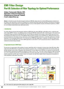
Fig. 1. The geometry of the test enclosure with dual-perforated screens.
The finite-difference time-domain (FDTD) method has been widely applied in solving many types of electromagnetic problems. It possesses the advantages of simple implementation for relatively complex problems and high accuracy. A rectangular test enclosure with faces accommodating perforated screens was investigated experimentally and with FDTD modeling. The measurements and modeling results for dual-perforated screens were compared. Undesirable peaks in the EMI spectrum due to the high- resonances of the small cavity between the dual screens were observed and investigated. Those resonances could be predicted and eliminated through the utilization of a perforated lossy material. The perforation pattern of the lossy material was chosen to avoid impeding airflow between the dual perforated screens. The EMI reduction as a function of spacing between the dual-perforated screens was also studied with FDTD modeling. II. MEASUREMENTS AND FDTD MODELING A shielding enclosure mimicking an actual product enclosure for a file server is shown in Fig. 1. The interior dimensions of the enclosure were 40 cm 20 cm 50 cm. One-inch copper tape with a conductive adhesive was used as an electromagnetic seal along the seams in the interior. The enclosure was constructed of five pieces of 0.635-cm-thick aluminum and one plate of 0.165-cm-thick aluminum for the face containing the perforated cm cm screens. A terminated feed probe at
0018–9375/00$10.00 © 2000 IEEE
136
IEEE TRANSACTIONS ON ELECTROMAGNETIC COMPATIBILITY, VOL. 42, NO. 2, MAY 2000
in the anechoic chamber. The far-zone electric field provides a quantitative measurement of the levels of EMI and is related to the -parameters by [9]
(1)
Fig. 2. The positions of the virtual surfaces against the PML and enclosure.
was employed as an exciting source driven through a typebulkhead connector. The center conductor of the connector was soldered to a 0.16-cm diameter wire spanning the width of the cavity and terminating on the opposite cavity wall with a 1206 package size surface-mount (SMT) nominal 47- resistor soldered to a 1.5 in 1.5 in square of conductive adhesive copper lossy material (Milliken Contec®) tape. A layer of with a thickness of approximately 1 cm was placed against the cm wall to reduce the artificially high of the enclosure. This loss has previously been shown to approximate that associated with a populated printed circuit board (PCB) [7]. An alternative source, consisting of a patch structure was also used to mimic a driven heatsink within a computer server enclosure [8]. The center of a 5-cm 9-cm copper patch was connected to a 3-cm long wire extending from the center conductor of the bulkhead connector. For the case of a patch source excitation, a populated motherboard instead of a sheet of lossy material was used to load the test enclosure. Due to the limited availability of test sites, some of the following measurements were performed in a 3-m anechoic chamber, while the others were made in a shielded room loaded was with absorbing cones. Nevertheless, in all cases, measured with a Wiltron 37 247A network analyzer. Port 1 was connected to the interior source in the enclosure under test and Port 2 was connected to a log-periodic dipole-array receiving antenna. The network analyzer was placed outside the anechoic . Calibration was chamber or shielded room to measure performed to the type- connector on the test enclosure and the antenna connector. Far-zone electric field measurements were made with a separation of 3 m between the enclosure and the receiving antenna
is the antenna factor of the receiving antenna, and where is the incident voltage at Port 1, which is 0.5 mV for the scaled 1-mV source with 50- source impedance. A scaled 1-mV source is used for the purpose of comparison with FDTD modeling, and radiated EMI levels. The FDTD method was employed to model the test enclosure excited by a terminated feed probe. A cell size of 0.5 cm 0.5 cm 1.0 cm was employed in the FDTD modeling. Aluminum plates were modeled as perfect electric conductor (PEC) surfaces by setting the tangential electric field to zero on the cavity walls. The wire feed probe was modeled with a thin-wire algorithm [10]. The source was modeled by a simple voltage source mV, with a 50- resistance incorporated into a single cell at the feed point. The magnetic fields circling the source were modeled in the same fashion as a thin wire thereby giving the cross section of the source a specified physical dimension [11]. The SMT resistor was modeled as a lumped element using a subcellular algorithm [12]. The width of the SMT resistor is approximately that of the feed-wire diameter and the physical cross-section dimensions were modeled with the same diameter as that of the feed wire by modifying the magnetic field components circling the SMT in the same fashion as for the source. The lossy material was modeled by a one-cell layer of conS/cm. For the ducting material with conductivity electric field components inside the conducting layer, the conS/cm ( was the thickness of the ductivity material) was employed, while the conductivity S/cm was employed for the components on the interface of the conducting layer and free-space [10]. Perfectly matched layer (PML) absorbing boundary conditions were employed for the three-dimensional FDTD modeling [13]. The PML absorbing layers surrounding the enclosure were six cells away from the conducting planes without the apertures and eight cells away from the conducting plane containing the apertures. A time history of 10 000 time steps was recorded in all the FDTD modeling. Prony’s method was then used to extrapolate an additional 80 000 time steps [14]. The number of modeled time steps was chosen to satisfy general criteria on a sampling window [15]. The accuracy of the extrapolation was checked by running one FDTD simulation out to 40 000 time steps. The relative deviation between the extrapolation and the FDTD result was less than 2%. The computational time required on a workstation was then reduced from approximately 160 to 20 h. The far-zone field was obtained by applying equivalence principles to the FDTD modeling results. The FDTD method was used to calculate the electric and magnetic fields on a virtual surface completely surrounding the FDTD model of the enclosure. From the calculated values of the electric and magnetic fields on this surface, equivalent magnetic and electric surface current distributions were determined [16],[17], and the fields at 3 m (far field) were extracted. The average of the magnetic field
LI et al.: EMI REDUCTION FROM AIRFLOW APERTURE ARRAYS
(a)
(b)
(c) Fig. 3. The radiation from single- and dual-perforated screens from (a) FDTD modeling; (b) measurements; and (c) comparison between the measurements and FDTD modeling on the single and dual screens.
offset by one-half cell from the electric field was used to compensate for the phase difference between the magnetic field and
137
electric field components. The positions of the virtual surfaces were three cells away from the enclosure surfaces, as shown in Fig. 2. The spacing between the virtual surface and PML was varied from two to six cells and the change of the corresponding far fields was within 1 dB. Thus, the above four-cell spacing between the PML and enclosure surface was adequate for the FDTD modeling. A considerable number of cells is required in order to accurately model an aperture using FDTD [18]. The FDTD modeling results from the above discretization of 0.5 cm 0.5 cm 1 cm may result in significant inaccuracy of the absolute EMI level for the apertures investigated. Since the size of the present computational problem including PML’s was 500 000 cells, further modeling refinement in the apertures was not possible due to limitations of computational resources. Consequently, the 1-cm 1-cm apertures were modeled using only four cells. Since only relative radiation is of concern, the conclusions for the comparison between the dual- and single-perforated screens are still reliable. However, in order to compare these numerical modeling results with experimental measurements an additive correction is found to be necessary [18]. The effect on the measurements of the aluminum plate thickness of the aperture array panel was considered as well, using (dB) ( is the the empirical estimate of attenuation of diameter of the circle equivalent to the square) [1]. The attenuation factor was 4.7 dB for the single-perforated screen, and 9.4 dB for the dual-perforated screen. These factors were applied to the measurements to facilitate comparison with the zero-thickness case used in the modeling. FDTD modeling results are shown in Fig. 3(a) for the EMI level for three cases. The first case results from EMI coupling through a single screen configuration with the observation point located 3 m away from the screen in the perpendicular (broadside) direction. In the second case, the single screen configuration was replaced with a dual-screen configuration, while maintaining the same observation point location. In the third case, the observation point is located 3 m from the center of the front screen in the direction parallel (end fire) to the plane of the outer screen. The high- EMI peaks observed at 0.83 and 1.04 GHz in the “end-fire” case correspond to the two lowest calculated resonances [19]—0.84 and 1.06 GHz for the small (1-cm-thick) cavity between the two perforated screens. More significantly, these peaks indicate that the relative EMI advantage of the dualscreen configuration, approximately 20 dB in the broadside direction, is offset by the two peaks observed in the end-fire direction. Measured results for the same three cases are shown in Fig. 3(b). In addition, a fourth case consisted of placing two pieces of ) in the small cavity be5-cm 15-cm lossy material ( tween the two perforated screens. In this fourth case, included in Fig. 3(b), the high- resonances associated with the small cavity have disappeared, and a general EMI reduction of approximately 20 dB was achieved even though the amount of lossy material was insufficient to completely fill the region between the two screens. The broadside radiation was used in the single-screen configuration to compare the effect of single and dual screens since both measurements and modeling indicated
138
IEEE TRANSACTIONS ON ELECTROMAGNETIC COMPATIBILITY, VOL. 42, NO. 2, MAY 2000
Fig. 4. The design of the lossy material pattern utilized between the dual-perforated screens to eliminate the unwanted highbetween them.
that the EMI from a single screen was maximum at the broadside observation point. Finally, Fig. 3(c) shows a comparison of the measured and modeled single and double-screen EMI levels in the broadside direction. As previously noted, the FDTD modeling results have been raised by 10 dB to compensate for the inadequate number of computational cells in each aperture. All of the measurements and modeling results cited above were performed for a feed-probe excitation source with the measurements being made in an anechoic chamber. Additional measurements were subsequently made for a test enclosure excited with a patch source. The enclosure was loaded with a populated motherboard from a production system. These measurements were made in a shielded room loaded with absorbing cones along the walls. Only relative measurements were of concern. No attempt was made to compare the measurements and FDTD modeling because of the limitation in the measurement environment. Specifically, the shielded room measurements had a higher noise floor and also had several spurious EMI peaks associated with room resonances. Further, the room was too small for 3-m measurements. A lossy material pattern was designed to accommodate four apertures in the conducting screens for each aperture in the lossy material, as shown in Fig. 4. A Milliken polyester nonwoven material with a surface conductivity of was used. In contrast with the previous lossy material, the Milliken material was sufficiently stiff to allow for the cutting of apertures. As indicated above, only a partial filling of the small cavity was required. It was not necessary to have a one-to-one correspondence of the metal aperture and lossy material aperture. The measured frequency band was from 0.5 to 2.1 GHz. The measured results for the observation point broadside to the aperture array face are shown in Fig.
Q resonances due to the small cavity
5. The measured curves were not as smooth as those in the anechoic chamber due to the resonance effects of the shielded room. The EMI peaks due to the small cavity introduced by the dual perforated screens without the lossy material pattern in between resulted at approximately 1.04, 1.52, 1.64, 1.84, 2.02, and 2.08 GHz. These undesirable resonances and EMI peaks were significantly reduced, as shown in Fig. 5, with the addition of the perforated lossy material between the screens. An overall EMI reduction of more than 20 dB resulted. A similar set of measured results for end-fire observations is shown in Fig. 6. The broadside single-screen measurement is provided as a reference. The dual-screen end-fire results in this figure contain a number of resonant peaks. Many of these peaks line up closely with the calculated resonant frequencies of the small cavity between the screens. A few peaks seem to correspond to room resonances—for example, the peak at around 0.85 GHz was probably associated with a room resonance since it was absent from the anechoic chamber data shown in Fig. 3. Nevertheless, the incorporation of lossy material between the two perforated screens can be seen to significantly reduce many of the dominant EMI peaks in the end-fire direction. Finally, the effect of spacing between the dual-perforated screens was investigated with FDTD modeling only since the modeling results suggested that the measured results for larger spacing (1 cm) would fall below the noise floor of the measurements. Spacings of 2 and 4 cm were modeled, and the results are shown in Fig. 7. For the spacing of 1, 2, and 4 cm, EMI reductions of 20, 30, and 45 dB, respectively, resulted. Here the observation point was broadside to the array panels in front of the perforated screens. The undesirable resonances were not observable at this point. They can be eliminated with
LI et al.: EMI REDUCTION FROM AIRFLOW APERTURE ARRAYS
Fig. 5.
Measured results in broadside direction for patch source excitation.
Fig. 6.
Measured results in end-fire direction for patch source excitation.
the utilization of a lossy material between the dual-perforated screens. In practice, however, large spacings between the perforated screens may not be acceptable because they could impede the airflow by introducing turbulence between the screens. However, for close spacings such as 1 cm, this thickness can be filled with a perforated lossy material pattern to reduce EMI without disturbing the airflow.
139
III. SUMMARY AND CONCLUSION Measurements and numerical modeling were utilized to study EMI reduction utilizing dual-perforated screens for airflow arrays in a shielding enclosure. The results show that a dual-perforated screen with an interstitial lossy material pattern can significantly reduce the EMI from shielding enclosures as compared
140
IEEE TRANSACTIONS ON ELECTROMAGNETIC COMPATIBILITY, VOL. 42, NO. 2, MAY 2000
[15] X. Luo, M. Li, and J. L. Drewniak, “Time history extrapolation for FDTD modeling of shielding enclosure designs and EMI antenna geometries,” in Proc. IEEE Electromagn. Compat. Symp., Denver, CO, Aug. 1998, pp. 1172–1177. [16] R. J. Luebbers, K. S. Kunz, M. Schneider, and F. Hunsberger, “A finite-difference time-domain near zone to far zone transformation,” IEEE Trans. Antennas Propagat., vol. 39, pp. 429–433, Apr. 1991. [17] M. Li, J. Nuebel, J. L. Drewniak, R. E. DuBroff, T. H. Hubing, and T. P. VanDoren, “EMI from cavity modes of shielding enclosures—FDTD modeling and measurements,” IEEE Trans. Electromagn. Compat., to be published. [18] M. Li, J. Nuebel, J. L. Drewniak, T. H. Hubing, R. E. DuBroff, and T. P. VanDoren, “EMI from airflow aperture arrays in shielding enclosures—Experiments, FDTD, and MoM modeling,” IEEE Trans. Electromagn. Compat., to be published. [19] C. A. Balanis, Advanced Engineering Electromagnetics. New York: Wiley, 1989.
Fig. 7. The FDTD modeled EMI reduction for different spacings between the dual-perforated screens.
to a single perforated screen. This design may offer a cost-effective alternative to waveguide air vents for airflow in shielding enclosures.
Min Li was born in China in 1968. She received the B.S. (honors) and M.S. (honors) degrees in physics from Fudan University, Shanghai, China, in 1990 and 1993, respectively, and the M.S. and Ph.D. degrees in electrical engineering from the University of Missouri-Rolla, in 1996 and 1999, respectively. Since 1995, she has studied and worked in the Electromagnetic Compatibility Laboratory, University of Missouri-Rolla. Her research interests include numerical and experimental study of electromagnetic compatibility problems. She is currently with Lucent Technologies. Dr. Li was supported by a Dean’s fellowship and assistantship in her research and studies. She is the winner of the 1998 IEEE EMC Society President Memory Award.
REFERENCES [1] T. Y. Otoshi, “A study of microwave leakage through perforated plates,” IEEE Trans. Microwave Theory Tech., vol. MTT-20, pp. 235–236, Mar. 1972. [2] C. C. Chen, “Transmission through a conducting screen perforated periodically with apertures,” IEEE Trans. Microwave Theory Tech., vol. MTT-18, pp. 627–632, Sept. 1970. [3] S. Criel, L. Martens, and D. D. Zutter, “Theoretical and experimental near-field characterization of perforated shields,” IEEE Trans. Electromagn. Compat., vol. 36, pp. 161–168, Aug. 1994. [4] K. F. Casey, “Electromagnetic shielding behavior of wire-mesh screens,” IEEE Trans. Electromagn. Compat., vol. 30, pp. 298–306, Aug. 1988. [5] W. Wallyn, F. Olyslager, E. Laermans, D. D. Zutter, R. D. Smedt, and N. Lietaert, “Fast evaluation of the shielding effectiveness of rectangular shielding enclosures,” in Proc. IEEE Electromagn. Compat. Symp., Denver, CO, Aug. 1998. [6] M. Li, S. Radu, J. Nuebel, J. L. Drewniak, T. H. Hubing, and T. P. VanDoren, “Design of airflow aperture arrays in shielding enclosures,” in Proc. IEEE Electromagn. Compat. Symp., Denver, CO, Aug. 1998, pp. 1059–1063. [7] M. Li, S. Radu, J. L. Drewniak, T. H. Hubing, T. P. VanDoren, and R. E. DuBroff, Electromagn. Comp. Lab./Univ. Missouri-Rolla, Tech. Rep. TR98-1-029. [8] S. Radu, Y. Ji, J. Nuebel, J. L. Drewniak, T. P. Van Doren, and T. H. Hubing, “Identifying an EMI source and coupling path in a computer system with sub-module testing,” in Proc. IEEE Electromagn. Compat. Symp., Austin, TX, Aug. 1997, pp. 165–170. [9] D. Morgan, A Handbook for Testing and Measurement. Stevenage, U.K.: Peter Peregrinus, 1994. [10] A. Taflove, Advances in Computational Electrodynamics: The FiniteDifference Time-Domain Method. Boston, MA: Artech House, 1998. [11] D. M. Hockanson, J. L. Drewniak, T. H. Hubing, and T. P. Van Doren, “FDTD modeling of common-mode radiation from cables,” IEEE Trans. Electromagn. Compat., vol. 38, pp. 376–387, Aug. 1996. [12] Y.-S. Tsuei, A. C. Cangellaris, and J. L. Prince, “Rigorous electromagnetic modeling of chip-to-package (first-level) interconnections,” IEEE Trans. Components Hybrids Manuf. Technol., vol. 16, pp. 876–882, Dec. 1993. [13] J. P. Berenger, “Perfectly matched layer for the absorption of electromagnetic waves,” J. Comput. Phys., vol. 114, pp. 185–200, Oct. 1994. [14] W. L. Ko and R. Mittra, “A comparison of FDTD and Prony’s methods for analyzing microwave integrated circuits,” IEEE Trans. Microwave Theory Tech., vol. 39, pp. 2176–2181, Dec. 1991.
Joe Nuebel is currently a Staff Electromagnetic Compatibility (EMC) Engineer at Sun Microsystems, Palo Alto, CA. For over 15 years he has been working in the field of electromagnetic compatibility. His background also includes immunity, safety, and NEBS testing for Telco. He also initiated university research at Sun in the area of EMC to assist in determining possible future EMC design concepts.
James L. Drewniak (S’85–M’90) received the B.S. (highest honors), M.S., and Ph.D. degrees in electrical engineering from the University of Illinois, UrbanaChampaign, in 1985, 1987, and 1991, respectively. He joined the Electrical Engineering Department, University of MissouriRolla, in 1991, where he is part of the Electromagnetic Compatibility Laboratory. His research interests include the development and application of numerical methods for investigating electromagnetic compatibility problems, packaging effects, and antenna analysis, as well as experimental studies in electromagnetic compatibility and antennas.
Todd H. Hubing (S’82–M’82–SM’93) received the B.S.E.E. degree from the Massachusetts Institute of Technology, Cambridge, the M.S.E.E. degree from Purdue University, West Lafayette, IN, and the Ph.D. degree in electrical engineering from North Carolina State University, Raleigh, in 1980, 1982, and 1988, respectively. He is a Professor of electrical engineering at the University of Missouri-Rolla (UMR) and one of the Principal Faculty in the UMR Electromagnetic Compatibility Laboratory. Prior to joining the faculty at the University of Missouri-Rolla in 1989, he was an EMC Engineer at IBM, Research Triangle Park, NC. He has authored or presented more than 70 technical papers, presentations, and reports on electromagnetic modeling and EMC-related subjects. He also writes the satirical Chapter Chatter column for the IEEE EMC Society Newsletter. Since joining the University of Missouri-Rolla, the focus of his research has been measuring and modeling sources of electromagnetic interference. Dr. Hubing is on the Board of Directors for the IEEE EMC Society.
LI et al.: EMI REDUCTION FROM AIRFLOW APERTURE ARRAYS
Richard E. DuBroff (S’74–M’77–SM’84) received the B.S.E.E. degree from Rensselaer Polytechnic Institute, Troy, NY, in 1970, and the M.S. and Ph.D. degrees in electrical engineering from the University of Illinois at Urbana-Champaign, in 1972 and 1976, respectively. From 1976, he held a Postdoctoral position in the Ionosphere Radio Laboratory, University of Illinois at Urbana-Champaign, and worked on backscatter inversion of ionospheric electron density profiles. From 1978 to 1984 he was employed as a Research Engineer in the Geophysics Branch, Phillips Petroleum, Bartlesville, OK. Since 1984 he has been affiliated with the University of Missouri-Rolla and is currently a Professor in the Department of Electrical and Computer Engineering.
141
Thomas P. Van Doren (S’60–M’69–SM’96) received the B.S., M.S., and Ph.D. degrees from the University of Missouri-Rolla, in 1962, 1963, and 1969, respectively. From 1963 to 1965, he served as an Officer in the U.S. Army Security Agency, Ft. Huachuca, AZ, and Arlington, VA. From 1965 to 1967 he was a Microwave Engineer with Collins Radio Company, Dallas, TX. Since 1967 he has been an electrical engineering Faculty Member at the University of Missouri-Rolla, where he is currently a Professor. His research interests concern developing circuit layout, grounding, and shielding techniques to improve electromagnetic compatibility. He has taught short courses on electomagnetic compatibility to over 10 000 engineers and technicians representing 200 corporations. Dr. Van Doren received an IEEE EMC Society Richard R. Stoddard Award for his contributions to EMC research and education in 1995. He is a Registered Professional Engineer in the state of Missouri and a Member of Eta Kappa Nu, Tau Beta Pi, and Phi Kappa Phi.