Interferogram phase noise reduction using morphological and modified median filters. Ana Llicia Bezerra Candeias'. J o d C. Mural. Lucian0 V. Dutra'.
Interferogram phase noise reduction using morphological and modified median filters Ana Llicia Bezerra Candeias' J o d C. Mural Lucian0 V. Dutra' Jo& R. Moreira2 'INPE - Instituto Nacional de Pesquisas Espaciais DPI - Divisilo de Processamento de Imagens Avenida dos Astronautas, 1758 12227-010 Silo J o d dos Campos SP - BRAZIL T +55 123 418977 Ext. 533 F +55 123 218743 EMaik [analucia;mura;dutra]@dpi.inpe br 2DLR German Aerospace Research Establishment 82230 Oberpfaffenhofen,Germany Ehhil: [ h f 3 9 1 @vm.op .dlr .de Abstract - Phase unwrapping for S A R Interferometry is one tral pixel of a suitable supporting area around the pixel being of the barriers for obtaining an operational interferometric filtered. S A R system (MAR). For filtering the phase one uses mainly a low pass linear filter applied on the complex interferometric After the phase noise reduction, the residues method [6] is image before evaluating the phase. This paper compares three applied for evaluating the filters results. The paper describes different non linear methods which filter the wrapped phase the fitering methods and gives a comparison between them. map. The first method is based on a morphological filter, the A significant reduction of the number of residues, by using second one is a modified median filter and the third is a modi- these non linear filters, is proved. fied mode filter. All filters are built considering the periodic MATHEMATICAL MORPHOLOGY CONCEPTS character of the wrapped phase function. The characteristics of these filtering approaches are compared, and the number of The necessary Mathematical Morphology concepts to underresidues are calculated after each filtering step. stand this paper is resumed here. An introduction of MatheKeywords: Interferometry, Mathematical Morphology, matical Morphology can be found in [7] and [81. More details InSAR, SAR, ERS-1, Non Linear Filtering, Remote Sensing. see in [l], [4] and [5]. INTRODUCTION
In Radar Interferometry the phase unwrapping [3], is an important step towards of an interferometric S A R system (InSAR). The speckle noise disturbs the quality of the interferogram, so a suitable method has to be used to improve the quality of the data. In the literature, for filtering the phase, one uses mainly a low pass linear filter applied on the complex interferometric data, before evaluating the phase. This procedure increases the signal to noise ratio of the phase field and decreases the number of residues [6] . In this paper a complementary approach is used. Non linear filters are applied to the wrapped phase field with the objective of improving its quality, without further sacrificing the spatial resolution. Three different non linear fiiters are considered and compared. method is based on mathematical morphology ne adapted filtering theory 121. Because of the periodic character of the wrapped phase function (more properly stating, the phase is a closed domain in a ring) it is necessary to modify the definition of dilation and erosion operations to preserve fie partialorderingproperty. Thefilteringofphasenoiseconsists on a sequence of modified erosion and dilation operations. The second method is a modified median filtering. The standard median filtering is not suitable for use with phase values. Phase can be defined , for example between -n and n or between 0 and b,they are the same information, but the median can be different in either case, which is not desirable. The third method, the mode filter, is easily adapted to consider the periodic character of the phase function. It uses a 2n sliding window over the phase, centered on the phase value of the cen0-7803-2567-2195 $4.00 0 1995 IEEE
Let Z be the set of integers. Let E be the a rectangle of Z2 and K is a closed interval of Z or R.The collection of functions
from E to K will represent the gray-scale image of interest (the binary images are seen like a particular case of grey-scale images). Such collection will be denoted KE,and f,g, fl and f2 will denote generic elements of KE. The intersection of fl e f2, denoted fl A f 2 , is the function in KE given, for any x E E, by (fl A f&x) = min (fl(x), f2(x)); the union of fl and f2, denoted fl V f 2 , is the function in KE given, for any x E E, by v f 2 ) b ) = max Vl(X), f 2 W ) . The definitions of two important subclasses of operators, namely dilations and erosions, are recalled using the fact that (Z2, +) forms an Abelian group.
vi
Let B be a subset of Z2,called structural element. The translathm of B by any vector h in z2,is denoted Bh; that is, Bh = ( x + h : x E B 1. The B m s P e o f B is denoted B', that is, B' = ( - X :X E B 1. The C0mpk"t Of B is denoted B", that is, B' = (1:x B ) . The dilation of f by B is the function d,(f) in KE, given, for any x in E, by d,y>(x) = maxV(y):y EB:RE).Theemsionof f b y B i s in KE, given, for any x in E, by the function EB(n(x)= min : E B , n E 1. netwo operators 8, and respectively, dilation and erosion by B.. EB are
v~y)
USUdly, in image prOCeSShg, a Unique p d d order is defined for all the pixel positions. But in Certain Cases, like interferometry phase noise reduction, we have to consider a different partial order at each pixel position. In such cases it is possible to define a dilation-like and an erosion-like operators. Banon [2] has suggested the following definitions:
166
The dilation-like operator of f by B, called here ewansion, is denoted by the function d; v) in K“,given, for any x in E, by:
includes the center pixel of the mask, the center pixel will remain unchanged.
a;U, =
This also has the additional property of potentially producing the whole set of available a priori phases, because for each area (mask) being filtered the set of bins can be positioned elsewhere, that is, not coincidentally with the previous position. Another approach for bin set positioning is selecting a phase present on the mask and using it as a boundary between one pair of bins. This also guarantees a potential production of all a priori availablephases.
V ( 4 - v) f- ma+@) f- (v - f ( 4 ):Y E B: n E}.
(1)
Where f- defines the addition modulus I (the length of K), v is the “center” of interval K and where the “max” is defined from the usual partial order on Z or R. For example, for K = [-x,n],weusel = 2zandv = 0. The erosion-like operator of f by B, called here contraction, is the function E; U, in K”,given, for any x in E, by:
~JU,(X)=
V ( 4 - v) j- m i n e w j- (v - f ( x ) ) :Y
With the mode found, it is possible to position a ~ J Cwindow centered on this mode value, and calculate the average, the median, or any other suitable moment, considering this range.
E Bxn E } . (2)
METHODOLOGY AND RESULTS
It is worthwhile, to observe that, in general, these new operators are neither dilation nor erosion, that is, they do. not verify the following properties:
rYV1 Vf&) = rYVl(x)) v r Y ( f Z W ) . for dilation supposing that 9 is a transformation. And
(3)
VVi AfZx-4 = ryVl(x)) A PVz(x)). for erosion supposing that ry is a transformation.
(4)
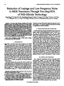
The interferometricimage was preliminarily filtered by a 3x5 box filter in range and azimuth respectively, resulting a spatial
resolution of approximately 20x20m (Figure 1). The interferogram f is then obtained and filtered, only in the areas where the residues can be found, by the modified morphological, wrapped median and mode filters.
MODIFIED MEDIAN AND MODE FILTERS CONCEPTS
The modified morphological filter used is:
The standard method for calculation of the average or the median is ill defined for the phase function,because it will give different answers, once these are calculatedconsidering different ranges, for example from -a to n or from 0 to 2 c . The mode however, if exists, can be found using a suitable method, that can assure unique result. The modified median filter of f over M , called here wrapped median, is the function p* in KE,given, for any x in E, by: PLv)(x) = T(x) - v) j- medianlfb) j- (v
For testing these filten it was used an X-SAR image pair (Etna, Italy) obtained in 1994 (SIR-C mission) and processed at D-PAF (Germany).
(7)
The second method used is the wrapped median and the resultant image is: f z = PLv)
(8)
Where M is a 3x3 mask.
-f (x)) :y E M, n E}. (5)
Where M is the mask used and “median” is defined from the usual partial order on Z or R .
The mode filter of fover M is the function q in KE,given, for any x in E, by: q M W )= mode fW :Y E M, n~ and fW E Si]. (6) Where “mode” is estimated by the following method: The interval K is divided in a suitable number of bins. Each bin has a length p and is denoted by pi, where i = 1, ....l/p. For example, for K = [ - n,n], we use 1 = 2n and p = 0.1. A local histogram is estimated over M.The mode is the center of the bin of the highest count.
Unlike exuacting a histogram from non periodic data, however, there is infinite possibilities of locating the boundaries of the bins over the data. This characteristic can be used to position the set of bins, in which the center of one of the bins is equal of the phase of the center pixel of a sliding mask on the phase field. This guaranteesthat, if the mode is in the bin which
The third method is the mode filter and the resultant image is: f3 = VMV) (9) M is a 3x3 mask. Table 1 presents the number of residues reduction rate calculated for each filtering method.
CONCLUSION
The results presented on Table 1. showed that applying conditional non linear filtering on the unwrapped phase can reduce the number of residues, so improving the performanceof phase unwrapping step. This paper also shows new ways of applying traditional non linear filters to periodic functions. With these improvement methods, we do not have change in spatial resolution of the phase image. Further work will be done testing other variations for median and morphological fiitering. Also a variation of morphological
167
filtering will be tested in the complex data before phase extraction. Contour following techniques will be also tested, after local filtering, seeking connection of broken fringes. ACKNOWLEDGMENT
The authors want to thank Dr.Gerald Banon from Image Processing Division of INPE for his helpfut assistance and the D-PAF to provide the X-SAR image used in this paper. This work was done with support of Fapesp (Fundaglo de Amparo B Pesquisa do Estado de S2o Paulo) contract 91/3532-2. REFERENCES [13 G. J. E Banon and J. Barrera, “Decomposition of
mappings between complete lattices by Mathematical Morphology. Part I: General lattices”, Signal Processing, 30, pp. 299-327, 1993. [a] G. J. E Banon, personal communication, 1995.
[3] H. Zebker and R. Goldestein, “Topographic mapping from interferometricS A R observations”J. Geophys Res., Vol. 91, pp. 49934999,1986. [4] J. Serra, “Image analysis and mathematical morphology”, Academic Press, London, 1982. [5] J. Serra, “Image analysis and mathematical morphology: Volume 2: Theoretical advances ” Academic Press, London, 1988. [6] R. M. Goldstein, H. A. Zebker and C. Werner, “Satellite radar interferometry: two-dimensional phase unwrapping”,Radio Sci., vol. 23, pp. 713-720, 1988. [7] R. M. Haralick, S. R. Stemberb and X. Zhuang, “Image analysis using mathematical morphology”,IEEE Pattern Anal. Machine Intell., vol. PAMI-9, no. 4, pp. 532-555, Jul., 1987. [8] R. M. Haralick and L. G. Shapiro, “Computer and robot vision,” vol. 1, New York, Addison Wesley, 1991. R. C. Gonzalez and R. E. Woods, Digital image processing. Reading, MA, Addison-Wesley, 1992.
Fig. 1: Original interferogram 0. TABLE 1 - NLTMBER OF RESIDUES REDUCTION RATE
168