minimization and mustang for state assignment, and the industrial tools ... ing methods available in mustang, c) we present a delay model to provide routing.
Empirical Evaluation of Multilevel Logic Minimization Tools For a Lookup Table-based Field-Programmable Gate Array Technology Martine Schlag, Pak K. Chan and Jackson Kong
Computer Engineering University of California, Santa Cruz Santa Cruz, California 95064, U.S.A.
Abstract
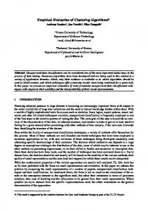
We examine empirically the performance of multi-level logic minimization tools for a lookup table-based Field-Programmable Gate Array (FPGA) technology. The experiments are conducted by using the university tools misII for combinational logic minimization and mustang for state assignment, and the industrial tools xnfmap for technology mapping and apr for automatic placement and routing. We measure the quality of the multi-level logic minimization tools by the number of routed con gurable logic blocks (CLBs) in the FPGA realization. We report three results: a) there is a linear relationship between the number of literals and the number of routed CLBs, and b) in all 34 MCNC-89 benchmark nite state machines, one-hot state assignment resulted in substantially less CLBs than any other state encoding methods available in mustang, c) we present a delay model to provide routing delay prediction based on fanout, and apply the model to estimate the delays of the FPGA implementation of logic expressions prior to technology mapping, place and route. These results are useful for prototyping a design in FPGAs, and then transferring the design to a di�erent technology (e.g., CMOS standard cell). It provides valuable information on the di�erence in performance of a design realized in di�erent technologies.
1 Introduction
The advent of FPGA technology provides a mechanism for rapid prototyping. When a prototype is operational, the design may be transferred to a di�erent technology (such as custom or semi-custom VLSI) for mass production. It is valuable to be able to predict di�erences in performance of a design across di�erent technologies. One way to achieve this is to use the same set of design tools at higher levels in the design ow, such as multi-level logic minimization tools for technology independent minimization, followed by quick technology mappings to di�erent technologies. We pose the following question. Is there an intermediate form that serves as the basis for estimation of performance of a design across di�erent technologies? 1
The performance of multi-level logic minimization tools for CMOS standard cell implementation is relatively well known and studied. But little is known about the performance of multi-level logic minimization tools with respect to FPGAs. So to answer this question, we examine empirically the performance of multi-level logic minimization tools for a lookup table-based FPGA realization [1]. The experiments are conducted by using misII2.0 for combinational logic minimization and mustang for state assignment. The vendor's supplied program xnfmap is used for technology mapping, and apr is used for automatic placement and routing 1. We measure the quality of the multi-level logic minimization tools in relationship with the FPGA technology by the number of routed con gurable logic blocks (CLBs) and speed of the realization of the prototypes. We present the following results: 1. There is a linear relationship between the number of literals and the number of routed CLBs. 2. In all 34 MCNC-89 benchmark nite state machines, one-hot state assignment resulted in substantially less CLBs than any other state encoding methods available in mustang. 3. We present a delay model to provide routing delay prediction based on fanout, and apply the model to estimate the delays of the FPGA implementation of logic expressions prior to technology mapping, place and route.
2 A lookup table-based FPGA architecture
Xilinx FPGAs are dense arrays of gates that can be con gured { and recon gured { by the system designer through software, rather than by chip manufacturer in the fabrication line. With realization times measured in hours, systems incorporating up to thousands of gates on a single FPGA can be designed, programmed and evaluated within a few weeks [1]. The basic building block which provides the logic functionality in the XC3000 series FPGA architecture is shown in Fig. 2. This is a Con gurable Logic Block (CLB), which has a maximum of 5 logic inputs. Each CLB has a programmable combinational logic section and two ip- ops. A programmable combinational logic section can implement any 5-variable logic function or two functions of at most 4 variables each, as long as they have at most 5 variables altogether. Each CLB also has two outputs called and , which drive the programmable interconnect networks (not shown). The outputs of the combinational logic section can go directly to and or through ip- ops FF1 and FF2. x
x
y
y
3 A system for rapid prototyping using FPGAs
As depicted in Fig. 1, our design environment is based on wireC which uses xdp as the front end for schematic entry [2]. We have con gured wireC to handle eqn format le generated by misII [3]. We built a parts library for wireC which outputs Xilinx Netlist
, which was developed by Exemplar Logic, Inc., has been frequently misidenti ed as the Xilinx mapper in the literature. Xnfopt does combinational logic synthesis, xnfmap is developed by Xilinx, and is a complete mapper. 1Xnfopt
2
File format (XNF). The XNF les are then mapped by the vendor's xnfmap technology mapper to generate LCA les. We use the vendor's apr program to place and route the LCA netlist to generate the nal design. The design can be simulated by susie [4] at the functional level before placement and routing, and at the timing level afterwards.
4 Relationship between the number of literals and number of CLBS
We study the performance of two technology independent minimization tools: misII and mustang for the FPGA technology. Because one of the goals of research in multi-level logic minimization is the development of technology independent minimization algorithms, literal count in logic expressions has been used as an indicator of the quality of their algorithms [5, 3, 6]. Both intuition [3] and empirical studies [7] support the use of this measure. In particular, the experiments reported in [7] were conducted with respect to standard cell technology. We study the performance of misII with respect to FPGA technology to further strengthen the argument. We use two benchmark suites. The rst suite of circuits come from the MCNC-89 nite state machine benchmarks [8]. Our experiments are conducted by using mustang for state assignment, and misII for logic expression minimization using the algebraic standard script once. Infeasible expressions (with the number of fanins greater than 5) are repetitively splitted. The logic equations are translated to XNF format and technology mapped by xnfmap to produce LCA les. The LCA les are then placed and routed by apr. Fig. 3 shows an empirical relationship between the number of literals and the number of (routed) CLBs that we obtained. It shows the ratio of literals to CLBs is roughly 5:1. Some state assignment strategies tend to generate designs that are not routable; this will be elaborated in Section 5. The second suite of circuits come from the MCNC-89 combinational logic benchmarks. Only those circuits that can be implemented with the XC3000 series FPGAs are included. The circuits are mapped using three di�erent lookup table-based technology mappers: Chortle-crf [9], xnfmap and rmap [10]. Fig. 4 shows an empirical relationship between the number of literals and the number of (routed) CLBs. Again, it shows the ratio of literals to CLBs is roughly 5:1, with no essential di�erence among di�erent technology mappers. The only exception is the C499 ECC benchmark which has a large number of XOR gates. This empirical result can be applied to guide the partitioning of a large design into multiple FPGAs. It can also be used to estimate whether a design can be accommodated in an FPGA, simply by counting the literals.
4.1 Characterization of technology mapping
In this section, we provide some intuition as to why the ratio of literals to CLBs is roughly 5:1. This requires some understanding of the interaction between misII and the mapper xnfmap. Notice that we are actually measuring the performance of misII in relationship to a single technology mapper xnfmap2. Other mappers for FPGAs exist [9, 11, 12, 13, 14], Xnfmap is a complete mapper, it does mapping of both combinational and sequential logic. Mappers such as mispga and chortle are limited to mapping of combinational logic. 2
3
but they are limited to combinational circuits. We believe that the pairing operation in xnfmap is quite universal, and would exist in any other future mapper. As mentioned earlier, an XC3000 CLB has a maximumof 5 logic inputs. A programmable combinational logic section can implement any 5-variable logic function or two functions of a maximum of 4 variables each. Each CLB also has two outputs, and . With the idea that the combination of gcx, gkx, and decomp operations in misII tends to break complex logic expressions into smaller subexpressions by factorization and sharing of common subexpressions, and a technology mapper would attempt to maximize the utilization of a CLB by pairing of small subexpressions. We o�er a simple explanation of why the ratio of literals to CLBs is roughly 5:1. Figs. 5.a to 5.d enumerate all the con gurations in which literals can share a CLB. The numbers in the gures illustrate the lower bounds on the ratios of literals to CLBs for each con guration. The number of literals can be much larger than the number of inputs, but misII doesn't seem to generate this type of expression with the benchmark circuits. Also, the exact ratio of literals to CLBs depends on the relative occurrences of these con gurations. In particular, if all con gurations are equally likely and all the literals appear as input variables to the CLBs (i.e., no intermediate variables are generated by the mapper), then we have Table 1.a. In practice, not all con gurations are equally likely. We studied 60 designs and determined their literal to CLB ratios. This statistic is summarized in Table 1.b. x
4
y
5 State assignment for FPGAS
We examine the problem of assigning values for the states in a nite state machine (FSM) so as to minimize the number of CLBs and delay. Research in multi-level logic minimization employs literal count in the combinational part of the FSM as the indicator of the quality of a state assignment algorithm [15, 16]. For that matter, it is not widely reported that one-hot encoding provides small literal counts. Perhaps it was dismissed because the number of ip- ops employed in the one-hot encoding scheme is the number of states. Hence, research in state assignment targeting multi-level logic minimization has focused on minimum-length (or close to minimum-length) encodings. It is a common belief that the cost in logic complexity of one-hot encoding is usually somewhat higher than for other methods, but it is generally not far out of line. Moreover, because the transitions in one-hot encoding are all two-step, it leads to circuits slower than could be built employing a single-transition-time assignment [17, p.177]. However, in the FPGA technology, ip- ops are essentially free in XC3000 series, as each CLB has one or two programmable ip- ops. The naive one-hot encoding after all may be the winner over elaborate minimum-length encoding schemes developed [18]3. We pose the following question. What is the best strategy, measured in terms of the number of CLBs and speed, among the options provided by the state assignment program mustang [15]?
5.1 State encoding for minimizing CLBs
The nite state machines are from the MCNC-89 benchmarks [8]. The experiment is conducted using mustang for state assignment, and misII for logic expression minimization applying the standard script once. The logic expressions are translated to XNF format and technology mapped by xnfmap to produce LCA les. The LCA les are then placed and routed by apr to produce the nal design, all using XC3020PC-84 packages . Tables 2 and 3 show the number of CLBs and literals for most of the encoding schemes available in mustang. We emphasize that the number of CLBs reported are the number of routed CLBs used to implement a complete FSM on an XC3020PC-84 package, not just the combinational part of it. Designs with more than 64 CLBs are not routed. Clearly, the number of CLBs using one-hot encoding is substantially less than any other encoding scheme available in mustang for all 31 nite state machines in Tables 2 and 3. To demonstrate further that the superiority of one-hot is not simply an anomaly of the benchmark set with small number of states, we introduce three larger designs: planet, scf, styr into the experiments. We report the literal and CLB counts in a separate Table 4; the designs are routed using di�erent packages. The same trend that one-hot is superior is again observed for these larger designs. More importantly, FSMs encoded in strategies other than one-hot often cannot be completely routed. In general, the number of literals can be further reduced by using a much longer optimization script in misII. However, the literal counts for one-hot encoding using the short standard script are comparable to other encoding methods using the long optimization script. 3
Our experiments were conducted in Aug 1990, without prior knowledge of [18].
5
5.2 State encoding and delay
It is informative to know the speed of the nite state machines under di�erent methods of encoding. Table 3 shows the speed reported by the design editor xact of FSMs encoded with di�erent strategies. Again, it shows that one-hot-encoded FSMs outperform FSMs encoded in other schemes overwhelmingly in speed. It is because one-hot encoding produces next-state logic functions which have fewer inputs than the next-state logic functions from minimum-length encodings. The one-hot encoding scheme suits the FPGA architecture which has limited fanin but ample ip- ops in a CLB. We present the logic equations of the one-hot encoded FSM bbara and the one generated by the minimumlength fanout-oriented option (-tp) in Tables 5.a and b, respectively.
6 Delay estimation from logic expressions
We have suggested a simple way of estimating the number of routed CLBs from the literal count of the logic expressions. We ask: can we estimate the delay of a routed design simply from the logic expressions, prior to technology mapping, placement and routing? This concept arose from the work of [19] on delay estimation from technology independent logic equations. There are two aspects to this question. One concerns the constituents of delay in a routed design. The second concerns the structures of a design before and after technology mapping onto a FPGA.
6.1 Delay components in an FPGA
Delays in FPGA-based design are layout sensitive. The sources of delay in a Xilinx FPGA [1] are: 1. Con gurable Logic Block delay: this is the delay due to the combinational logic, setup time, and ip- ops in a CLB. 2. I/O Block delay: this is the delay due to the I/O bu�ers and pads. 3. Interconnect delay: there are three types: a) Direct lines. The delay due to direct lines is less than a nanosecond. b) General-purpose interconnect and switch matrices. These are the primary constituents of the delay which can range from a few nanoseconds to tens of nanoseconds. c) Long lines. These rare interconnection resources are for routing global signals, but may be used for some \local" routing if the general purpose interconnect is exhausted. 4. Bu�er delay: this is due to repowering bu�ers at the output of some switch matrices which restore signal levels.
The structure of a logic circuit is dictated initially by the design. In the course of implementation, this structure may be altered by tools such as the logic minimizer, and the technology mapper. For example, if the number of variables in a logic expression exceeds 5 (infeasible), then the logic minimizer/technology mapper would have to decompose the logic expression into feasible sub-expressions. Intermediate variables and nodes are created during the decomposition, which in e�ect would increase the delay. Our premise is that the structure of a design is not altered much by the mapper. This is particularly true for a design consisting primarily of small logic expressions, for example, the combinational logic of a one-hot encoded FSM (see Table 4.a). In such designs, 6
the CLB and I/O Block delays are straightforward to determine, but the interconnect delays are sensitive to the structure of a design; we estimate the interconnection delay from the logic expressions based mainly on the fanouts of the logic variables. We shall present evidence to support this conclusion.
6.2 A delay model
In our delay model, we relate the interconnect delay to the number of fanouts of a signal. This arose from the observation that the XC3000 FPGA architecture has limited routing resources. As the fanout of a signal grows, it uses up more and more routing resources, and hence increases the delay. Fig. 7 shows the \nominal delay" of a signal versus fanout, which is determined in XACT by packing sink CLBs as closely as possible around a source CLB. For example, in Fig. 8, block EE is the source CLB and the rest are sinks. Block EE has a fanout of 24. So the \nominal delay" is not necessarily the best-case delay. The worst-case delay can be quite large and therefore is not as meaningful as the nominal delay. This delay model tends to underestimate the delays of large circuits because routing congestion is not taken into account. Also, the delay model may overestimate the delays of small circuits because of pairing (fanin to the same CLB). There are two knees in the curve in Fig. 7. The initial (roughly linear) portion of the curve would indicate that the signal is transmitted through the general-purpose interconnect and switch boxes. As the number of fanouts exceeds 8, the router starts to consume the long lines for routing. The second knee would indicate that another level of long lines and general-purpose interconnect are used. We apply the delay model to a timing veri er to estimate the \worst-case" propagation delay of one-hot encoded FSMs from their logic expressions. We plot both the measured and the estimated delays in Fig. 9. The mean error is ?4 12ns, and the overall relative error (O.R.E.) is 0.18, indicating a fairly accurate estimation. :
7 Conclusion
We have observed certain empirical facts about the performance of multi-level logic minimization tools in relationship to a lookup table-based FPGA technology. These observations are made based on speci c tools that are commonly used in lookup table-based FPGA designs. There is no intention to claim that these observations are universal. First, we suggested that as a rule of thumb, dividing the literal counts of a set of logic expressions by 5 gives an estimate of the number of routed XC3000 CLBs to implement the logic expressions. This result can be applied to guide the partitioning of the logic expressions portion of a large design into multiple FPGAs. We can estimate the number of routed CLBs to implement the logic expressions simply by counting the literals. We extended the idea to estimate the delays of the implementation of logic expressions prior to technology mapping, place and route. An empirical delay model is suggested which can be used for delay prediction based on logic expressions. Our results suggest that logic expressions are a good intermediate form to bridge the estimation of performance of a design across di�erent technologies. Second, we suggest that the one-hot state encoding strategy is a good candidate for nite state machines targeted for lookup table-based FPGA technology. One-hot encoded FSMs tend to be more routable and outperform some of their single-transition-time7
assignment counterparts by substantial margins, both in speed and the number of CLBs. Finally, we note that as there have been advances in algorithms for state assignment [20], it would be interesting to study the feasibility of MUSE for FPGA technology.
7.1 Acknowledgements
The authors are grateful for the comments of the referees. Martine Schlag was supported in part by the National Science Foundation Presidential Young Investigator Grant No. MIP-8896276. The authors thank Steve Kelem of Xilinx Inc. for his comments.
References
[1] XILINX: The Programmable Gate Array Data Book. 2100 Logic Drive, San Jose, CA 95124, 1991. [2] C. Ebeling and Z. Wu, \WireLisp: Combining graphics and procedures in a circuit speci cation language," in IEEE International Conference on Computer-Aided Design ICCAD-89, (Santa Clara, CA), pp. 322{325, IEEE Computer Society Press, 5{9 November 1989. [3] R. K. Brayton, R. Rudell, A. Sangiovanni-Vincentelli, and A. R. Wang, \MIS: A Multiple-Level Logic Optimization System," IEEE Transactions on Computer-Aided Design of Integrated Circuits and Systems, vol. CAD-6, pp. 1062{1081, Nov. 1987. [4] ALDEC, 3525 Old Conejo Rd., Suite 111, Newbury Park, CA 91320, Susie Simulator: User's Guide, 1989. [5] D. Bostick, G. D. Hachtel, M. R. Lightner, P. Moceyunas, C. R. Morrison, and D. Ravenscroft, \The Boulder optimal logic design system," in IEEE International Conference on Computer-Aided Design ICCAD-87, (Santa Clara, CA), pp. 62{65, IEEE Computer Society Press, 9{12 November 1987. [6] K. Bartlett, W. Cohen, A. D. Geus, and G. Hachtel, \Synthesis and Optimization of Multilevel Logic under Timing Constraints," IEEE Transactions on ComputerAided Design of Integrated Circuits and Systems, vol. CAD-5, pp. 582{595, Oct. 1986. [7] M. Lightner and W. Wolf, \Experiments in Logic Optimization," in IEEE International Conference on Computer-Aided Design ICCAD-88, (Santa Clara, CA), pp. 286{289, IEEE Computer Society Press, 7{10 November 1988. [8] R. Lisanke, Logic Synthesis and Optimization Benchmarks, User Guide, Version 2.0. Microelectronics Center of North Carolina, MCNC P.O. Box 12889, Research Triangle Park, NC 27709, December 1988. [9] R. J. Francis, J. Rose, and Z. Vranesic, \Chortle-crf: Fast technology mapping for lookup table-based FPGAs," in ACM IEEE 28th Design Automation Conference Proceedings, (San Francisco, California), pp. 227{233, June 1991. 8
[10] M. Schlag, J. Kong, and P. K. Chan, \Routability-driven technology mapping for lookup table-based FPGAs," Tech. Rep. UCSC-CRL-92-06, Board of Studies in Computer Engineering, University of California at Santa Cruz, Santa Cruz, CA 95064, Feb. 1992. To appear in ICCD'92. [11] R. Murgai, Y. Nishizaki, N. Shenoy, R. K. Brayton, and A. Sangiovanni-Vincentelli, \Logic synthesis for programmable gate arrays," in ACM IEEE 27th Design Automation Conference Proceedings, (Orlando, Florida), pp. 620{625, June 1990. [12] R. Murgai, N. Shenoy, R. K. Brayton, and A. Sangiovanni-Vincentelli, \Improved logic synthesis algorithms for table look up architectures," in IEEE International Conference on Computer-Aided Design ICCAD-91, (Santa Clara, California), pp. 564{567, November 1991. [13] R. J. Francis, J. Rose, and K. Chung, \Chortle: A technology mapping program for lookup table-based eld programmable gate arrays," in ACM IEEE 27th Design Automation Conference Proceedings, (Orlando, Florida), pp. 613{619, June 1990. [14] K. Karplus, \Xmap: a technology mapper for table-lookup eld programmable gate arrays," in ACM IEEE 28th Design Automation Conference Proceedings, (San Francisco, California), pp. 240{243, June 1991. [15] S. Devadas, H.-K. Ma, A. R. Newton, and A. Sangiovanni-Vincentelli, \MUSTANG: State assignment of nite state machines targeting multilevel logic implementations," IEEE Transactions on Computer-Aided Design of Integrated Circuits and Systems, vol. CAD-7, pp. 1290{1299, December 1988. [16] M. Bolotski, D. Camporese, and R. Barman, \State Assignment for Multi-Level Logic using Dynamic Literal Estimation," in IEEE International Conference on Computer-Aided Design ICCAD-89, (Santa Clara, CA), pp. 220{223, IEEE Computer Society Press, 6{9 November 1989. [17] S. H. Unger, The Essence of Logic Circuits. Englewood Cli�s, New Jersey: Prentice Hall, 1989. [18] S. K. Knapp, \Accelerate FPGA macros with one-hot approach," Electronic Design, Sept. 1990. [19] D. E. Wallace and M. S. Chandrasekhar, \High-Level Delay Estimation for Technology-Independent Logic Equations," in IEEE International Conference on Computer-Aided Design ICCAD-90, (Santa Clara, CA), pp. 188{191, IEEE Computer Society Press, Nov. 1990. [20] X. Du, G. Hachtel, B. Lin, and A. R. Newton, \MUSE: A multilevel symbolic encoding algorithm for state assignment," IEEE Transactions on Computer-Aided Design of Integrated Circuits and Systems, vol. CAD-10, pp. 28{38, January 1991.
9
List of Figures 1 2 3 4 5 6 7 8 9
Design ow. Architecture of an XC3000-series Con gurable Logic Block. Routed CLBs vs literals of FSM benchmarks. Routed CLBs vs literals of combinational logic benchmarks. Di�erent pairing con gurations. The dashed line in the box denotes the partition of the lookup table into 2 smaller tables. Distributions of literals to CLBs (a) equiprobable (b) measured from 1271 CLBs, 60 designs. Nominal delay vs fanouts in an XC3020PC84-100. Measurement of nominal delay in XACT. Delays of one-hot encoded FSMs: measured (in XACT 2.12) vs estimated. : : : : : : : : : : : : : : : : : : : : : : : : : : : : : : : : : :
: : : : : : :
: : : : : : : : : : : : : : :
: : : : : : :
: : : : : : : : : : : : :
: : : : : : : : : : : : : : : : : : : : : : : : : : : : : : :
: : : : : : : : : : : : :
: : : : : : : : : : : : : : : : : :
11 12 12 13 14 14 17 18 19
List of Tables 1
2
3 4 5
Distributions of literals to CLBs (a) equiprobable (b) measured from 1271 CLBs, 60 designs. Number of literals and CLBs for di�erent state encoding strategies: obtained using misII standard script and Xilinx xnfmap and apr on an XC3020PC84-100. Mustang options are: -a graph embedding performed by using a simulated annealing-based algorithm; -e expand state codes to use up unused state codes; -n a state assignment option which uses a fanin-oriented algorithm to produce an encoding of states; -p a state assignment option which uses a fanout-oriented algorithm to produce an encoding of states; -t a variation in fanin and fanout oriented heuristics which sometimes produces better results; -r using random encoding with the default seed; -ran machine is encoded using random encoding with a random seed; -s states of the machine are assigned sequential codes. (Continuation from Table 2) Large designs: number of literals and CLBs for di�erent state encoding strategies using misII standard script, xnfmap and apr with default settings. Delay of unrouted designs are not available (NA). Combinational logics of FSM bbara (a) one-hot encoded (b) -tp ag encoded.
: : : : : : : : : : : : : : : : : : : : : : : : : : : : : : :
: : :
: : : : : : : : : : : : : : : : : : : : : : : : :
11
15 16
: : : : : : : : :
16
: : : : : : : : : : : : : : : : : : : : : : : : : : : : : : : : : : : : :
17
10
Schematic Entry
EQN
wireC
XNF
Functional simulator
High-level Language Bdsyn Logic mini
susie
espresso misII
XNF
Technology Mapper xnfmap
LCA
Auto Place and Route apr LCA
Timing simulator susie
Figure 1: Design ow. literals:CLB # of instances 1:1 0 2:1 1 3:1 1 4:1 4 5:1 4 6:1 4 7:1 2 8:1 2 mean 5.4 (a)
literals:CLB # of instances 1:1 2 2:1 30 3:1 73 4:1 288 5:1 336 6:1 442 7:1 83 8:1 17 mean 5.1 standard deviation 1.19 (b)
Table 1: Distributions of literals to CLBs (a) equiprobable (b) measured from 1271 CLBs, 60 designs.
11
INPUTs a b c d e
FF1 F
Combinational Function G
OUTPUTs x y
FF2
CLK
Figure 2: Architecture of an XC3000-series Con gurable Logic Block. 800
��?�� � � �� ?� | ���� ?� �|?��||�� � � � �����|?� �
600 Literals
400 200 0
~ �� ��~?�� ?� � | �~���|� � ���?� � ~ �| ? � �?��?~��| � � � � � � ? ������ ~|�|�� � � � � � � � � |�?�� �|��?|� ��� ? � � � ~ ~ ~ | ~ |?����� ~ ~ � � � ? � � � � ��?| �|~� ��?��?���� ��� ��?� �?? �?�|�� ��?�|~����?�|�� ����?|~� �� �� ����?�|~~� | � � | � � ~ � � � � ����?|� ~?~ ~ ~?~~�~~�~|~� | � � � � � � ? � � � � �|~��?��?~����|~��? ~ �|� ����|��?�
0
50 100 Number of CLBs
150
Figure 3: Routed CLBs vs literals of FSM benchmarks. 12
800 � xnfmap rmap � 2 chortle 600
2
C499
��
C499C499
�2 �
Literals 400
�2�2�2��2 ��
200
0
�2� 0
��2��2�2� �2���2 �2� 50
100 Number of CLBs
150
Figure 4: Routed CLBs vs literals of combinational logic benchmarks.
13
Use all 5 inputs literals:CLB
Use only 4 inputs literals:CLB
5:1
4:1
5:1
4:1
6:1
5:1
7:1
5:1
8:1
6:1 6:1 7:1
(a)
(b)
8:1
Figure 5: Di�erent pairing con gurations. The dashed line in the box denotes the partition of the lookup table into 2 smaller tables. Use only 3 inputs literals:CLB
Use only 2 inputs literals:CLB
3:1
2:1
3:1
2:1
4:1
4:1
4:1
3:1
5:1 (c)
6:1
(d)
Figure 6: Distributions of literals to CLBs (a) equiprobable (b) measured from 1271 CLBs, 60 designs. 14
FSM
# of mustang -a mustang -e mustang -n mustang -p mustang -r States # # # # # # # # # # Lit CLB Lit CLB Lit CLB Lit CLB Lit CLB bbara 10 173 33 146 30 135 27 125 26 151 32 bbsse 16 187 34 187 34 173 34 201 41 203 41 bbtas 6 46 8 45 7 46 7 52 9 62 10 beecount 7 110 20 101 18 106 20 107 18 114 20 cse 16 304 62 304 62 256 52 246 50 294 59 dk14 7 223 41 217 41 224 45 223 43 240 48 dk15 4 127 26 127 26 131 26 144 27 133 23 dk17 8 108 20 108 20 121 24 134 26 136 26 dk27 7 32 5 26 4 33 5 29 4 31 4 dk512 15 130 28 129 27 121 24 118 22 133 27 don le 24 333 69 314 64 329 65 297 58 323 65 dvram 6 309 65 295 61 278 57 283 59 305 64 ex2 19 247 51 276 59 196 43 231 53 234 51 ex3 10 99 18 98 20 105 20 137 27 145 30 ex4 14 116 22 128 24 108 20 120 23 115 22 ex5 9 124 28 131 26 112 21 112 22 128 26 ex6 8 144 26 144 24 136 26 135 26 136 25 ex7 10 132 27 122 25 90 16 135 27 135 27 keyb 19 246 48 278 56 242 48 430 87 377 80 lion 4 22 4 22 4 22 3 26 4 27 3 lion9 9 114 22 95 19 83 16 94 17 130 24 mark1 15 139 30 139 30 137 29 148 30 138 31 mc 4 37 6 37 6 23 4 34 7 39 7 opus 10 122 24 119 23 118 21 110 21 114 21 ris 5 281 58 283 59 273 59 279 60 292 59 s8 5 80 13 77 12 79 15 81 15 90 16 shiftreg 8 41 5 41 5 30 4 26 4 46 7 sse 16 187 34 187 34 173 24 201 41 203 41 tav 4 93 18 93 18 123 25 111 22 90 18 train11 11 123 23 109 21 110 21 115 23 129 26 train4 4 15 2 15 2 19 2 19 2 22 4 TOTAL 310 4444 870 4393 861 4132 803 4503 894 4715 947
Table 2: Number of literals and CLBs for di�erent state encoding strategies: obtained using misII standard script and Xilinx xnfmap and apr on an XC3020PC84-100. Mustang options are: -a graph embedding performed by using a simulated annealing-based algorithm; -e expand state codes to use up unused state codes; -n a state assignment option which uses a fanin-oriented algorithm to produce an encoding of states; -p a state assignment option which uses a fanout-oriented algorithm to produce an encoding of states; -t a variation in fanin and fanout oriented heuristics which sometimes produces better results; -r using random encoding with the default seed; -ran machine is encoded using random encoding with a random seed; -s states of the machine are assigned sequential codes.
15
FSM
mustang -ran
# # delay Lit CLB (ns)
bbara 135 28 bbsse 207 42 bbtas 55 8 beecount 109 20 cse 303 64 dk14 244 52 dk15 121 23 dk17 133 26 dk27 45 7 dk512 139 28 don le 319 64 dvram 311 62 ex2 241 51 ex3 127 27 ex4 127 26 ex5 127 25 ex6 147 27 ex7 137 31 keyb 411 85 lion 22 3 lion9 112 23 mark1 133 29 mc 23 4 opus 117 22 ris 279 59 s8 82 16 shiftreg 46 7 sse 201 40 tav 90 18 train11 115 23 train4 22 4 TOTAL 4680 944
98 140 64 121 175 160 113 121 70 102 145 162 146 97 103 111 133 113 NA 50 118 132 53 115 129 85 60 143 95 116 45
mustang -s
# # delay Lit CLB (ns)
120 23 181 34 48 6 107 21 252 50 242 53 144 27 115 23 33 5 126 27 318 66 255 52 236 51 106 20 117 23 108 23 131 25 114 20 254 49 22 3 96 19 141 30 23 4 117 21 283 58 87 13 49 9 181 34 111 22 114 23 16 2 4247 836
90 136 63 116 131 177 117 110 54 117 NA 131 158 87 127 102 110 96 144 49 111 139 51 117 134 79 58 120 99 116 43
mustang -tn
# # delay Lit CLB (ns)
133 25 169 32 55 8 106 20 239 51 224 45 121 23 116 24 33 6 109 20 319 71 267 57 194 40 101 18 114 22 116 23 136 26 87 17 236 49 22 3 85 15 138 32 23 4 124 21 273 55 78 15 30 4 169 32 111 22 109 22 19 2 4056 804
86 145 84 123 125 174 100 107 60 87 NA 145 138 86 117 113 114 91 188 50 122 126 53 107 163 98 62 137 93 116 48
mustang -tp
# # delay Lit CLB (ns)
125 26 180 33 52 9 113 19 237 46 223 43 144 27 103 20 28 5 118 21 297 58 267 59 221 46 132 29 115 22 114 22 134 26 130 27 430 87 26 4 83 14 148 30 34 7 113 21 285 59 81 15 30 4 180 33 111 22 107 22 19 2 4380 858
108 140 80 110 160 140 111 123 53 100 174 162 111 104 103 97 144 125 NA 48 109 134 64 128 155 87 58 149 100 97 49
(one-hot)
# # delay Lit CLB (ns)
79 15 128 26 29 5 82 14 195 37 149 28 108 21 70 12 29 4 63 11 159 29 83 26 129 21 75 12 72 18 73 11 109 23 77 11 194 42 31 4 65 10 99 27 33 6 90 20 114 22 61 11 36 5 128 26 79 15 79 12 25 4 2743 528
65 98 69 74 135 134 86 72 42 55 80 73 82 54 73 75 95 69 120 52 61 133 48 86 66 70 39 88 82 57 43
Table 3: (Continuation from Table 2).
FSM
# of States
planet1 48 scf 121 styr 30
mustang -r
# # delay Lit CLB (ns)
mustang -tn
# # delay Lit CLB (ns)
mustang -tp
# # delay Lit CLB (ns)
(one-hot)
# # delay Lit CLB (ns)
Package
641 144 NA 569 124 NA 614 132 NA 366 100 135.4 3042PC84-125 907 216 NA 852 205 NA 832 191 NA 529 138 123.4 3064PG132-100 657 149 NA 576 128 NA 555 121 NA 377 86 137.1 3042PC84-125
Table 4: Large designs: number of literals and CLBs for di�erent state encoding strategies using misII standard script, xnfmap and apr with default settings. Delay of unrouted designs are not available (NA).
16
INORDER = x3 x2 x1 x0 PS9 PS8 PS7 PS6 PS5 PS4 PS3 PS2 PS1 PS0; OUTORDER = NS9 NS8 NS7 NS6 NS5 NS4 NS3 NS2 NS1 NS0 z1 z0; NS9 = PS9*[94] + [91]*[95]; NS8 = [93]*[96] + PS6*[91] + PS8*[86]; NS7 = [92]*[97] + PS3*[91] + PS7*[86]; NS6 = PS8*[93] + PS6*[86]; NS5 = PS6*[93] + z1; NS4 = [91]*[98] + PS4*[86]; NS3 = PS7*[92] + PS3*[86]; NS2 = PS3*[92] + z0; NS1 = PS4*[91] + PS1*[86]; NS0 = PS1*[91] + PS0*[86]; z1 = PS5*![84]; z0 = PS2*[99]; [84] = !x2*![86]; [85] = PS0 + PS1 + PS4 + PS9; [86] = !x0 + !x1; [91] = !x3*[84]; [92] = x3*[84]; [93] = x2*![86]; [94] = !x3*!x2 + [86]; [95] = PS0 + PS7 + PS8; [96] = [85] + PS2 + PS3 + PS7; [97] = [85] + PS5 + PS6 + PS8; [98] = PS2 + PS5; [99] = x3*!x2 + [86];
(a)
INORDER = x3 x2 x1 x0 PS3 PS2 PS1 PS0; OUTORDER = NS3 NS2 NS1 NS0 z1 z0; [11] = !PS3*!PS2*![74]*[81]; [23] = !PS3*!PS2*PS1*!PS0*[79]; [29] = !PS3*[66]*[79]; NS3 = [72] + z0 + [29]; NS2 = !PS3*PS2*[65]*[74] + PS3*[68]*[80] + [73] + NS3 + [23]; NS1 = !PS3*[86] + [68]*[79] + z0 + z1 + [29] + [23] + [11]; NS0 = !PS3*PS0*[90] + [81]*[89] + [73] + [72]; z1 = [67]*[92]; z0 = PS3*[66]*[93]; [65] = !x0 + !x1; [66] = PS2*PS1*!PS0; [67] = !PS3*PS2*![74]; [68] = PS2*!PS1*PS0; [72] = [68]*[94]; [73] = [80]*[96] + z1 + [11]; [74] = !PS0 + !PS1; [77] = !x2*![65]; [79] = x3*[77]; [80] = !x3*[77]; [81] = x2*![65]; [83] = x1*!x0; [84] = !x1*x0; [85] = !x1*!x0; [86] = PS1*[65]*[88] + !x3*!x2*[66] + !PS1*[87] + PS0*[79]; [87] = !PS2*PS0*[81] + [79]; [88] = !PS0 + !PS2; [89] = !PS3*!PS0 + [68] + [66]; [90] = !PS2*[91] + !PS1*![77]; [91] = !x3*!x2*PS1 + [65]; [92] = [85] + [84] + [83] + [81]; [93] = [85] + [84] + [83] + [79]; [94] = PS3*[95] + !PS3*[80]; [95] = [85] + [84] + [83]; [96] = PS3*[66] + [67]; (b)
Table 5: Combinational logics of FSM bbara (a) one-hot encoded (b) -tp ag encoded.
�
15
Delay in ns
10 5 0 � 0
��
�
��� � �
��
� �����
�
�
� 5
10 15 Fanout
20
Figure 7: Nominal delay vs fanouts in an XC3020PC84-100. 17
Package 3020PC84, XACT PWR DN
P1 1 P1 0
P9
P8
P5
P4
P3
P2
GND
P8 4
P8 3
P8 2
P8 1
P7 8
P7 7
P7 6
P7 5
CCL K
P1 3
P7 3
T CL
P1 5
AA
AB
AC
AD
AE
AF
AG
AH
BA
BB
BC
BD
BE
BF
BG
BH
CA
CB
CC
CD
CE
CF
CG
CH
DA
DB
DC
DD
DE
DF
DG
DH
P7 2
P1 6
P1 7
P7 1
P7 0
P1 8
P1 9
P6 8
P6 7
P2 0
P2 1
P6 6
P6 5
VCC
VCC
P2 3
P2 4
P6 3
EA
EB
EC
ED
EE
EF
EG
EH
FA
FB
FC
FD
FE
FF
FG
FH
GA
GB
GC
GD
GE
GF
GG
GH
HA
HB
HC
HD
HE
HF
HG
HH
P6 2
P2 5
P2 6
P6 1
P6 0
P2 7
P2 8
P5 9
P5 8
P2 9
P5 7
BCL
P3 0
P5 6
M1 R D
M0 R
DPG M
P3 3 P3 4
P3 5
P3 6
P3 7
P3 9
P4 0
P4 2
GND
P4 4
P4 5
P4 6
P4 7
P4 8
P4 9
P5 2 P5 3
Figure 8: Measurement of nominal delay in XACT.
18
RST
Finite State Machines
cse dk14 mark1 keyb bbsse ex6 sse dk15 opus tav ex2 don le ex5 beecount ex4 dvram dk17 s8 bbtas ex7 ris bbara lion9 train11 dk512 ex3 lion mc train4 dk27 shiftreg
�
�
�: estimated delay �: measured delay
��
� � � � �� � � � � � � � � � � � � � � � � � � � � � � � � � � �� �� � � � � � � � � � � � � � � � � ��
� � � �
0 10 20 30 40 50 60 70 80 90 100 110 120 130 140 150 Delay (ns)
Figure 9: Delays of one-hot encoded FSMs: measured (in XACT
19
) vs estimated.
2.12