Mar 29, 2004 - maintenance procedure to maintain connection continuity between two ..... thus there is no cache invalidity issue in PNRP; 2) devices with good ..... and packet size 250 byte, emulating a real-time VoIP communication.
End-to-End Mobility Support in IPv6 Using Peer-to-Peer Technologies
Chuanxiong Guo Haitao Wu Kun Tan Qian Zhang Wenwu Zhu Christian Huitema March 29, 2004 Technical Report MSR-TR-2004-29
Microsoft Research Microsoft Corporation One Microsoft Way Redmond, WA 98052
End-to-End Mobility Support in IPv6 Using Peer-to-Peer Technologies Chuanxiong Guo, Haitao Wu, Kun Tan, Qian Zhang, Wenwu Zhu, and Christian Huitema ABSTRACT Despite voluminous mobility solutions that have been proposed in the past, none of them have been widely deployed today. To address the deployment difficulty in previous work, we propose an end-system based mobility management scheme in IPv6 (EMIPv6) for Internet hosts. In our design, we leverage distributed hash table-based peer-topeer systems to carry out scalable, robust and self-organizing name lookup for mobile hosts. And we adhere to the end-toend principle [1] by performing connection maintenance and data packet delivery between the two communicating hosts directly. This leads to small handoff latency and efficient packet delivery. When the mobility messages such as location updates cannot be delivered directly between the end hosts (e.g., due to firewalls, NATs, or simultaneous movement), we use the previously introduced peer-to-peer overlay to deliver them. We also ensure application transparency with the technique of node-pair binding cache. Our simulations results showed that our scheme achieves small name resolution latency by considering host heterogeneity into the design. We have implemented EMIPv6-based end systems. The experiments with our testbed demonstrated that a complete end-system based mobility solution is technically feasible and should be easy to deploy in the real world without the need of introducing new network components.
1. INTRODUCTION With rapid progresses in wireless, Internet, and embedded system technologies, more and more Internet applications such as Web browsing, email, Instance Messaging, and VoIP (voice over IP) are available on mobile devices such as laptops, PDAs, and cellular phones. However, due to the mobility nature of mobile devices, Internet-based applications face challenges in wireless networks. When a mobile device moves across wireless networks, the location of the device may change frequently, and as a result, its IP address may change accordingly. The current Internet uses IP address for both host identification and packet routing. Due to IP address change, a mobile host is hard to be located and the on-going connections of a mobile host may break. Two key challenges for mobility support in wireless IP networks are therefore how to efficiently locate a mobile
host (i.e., name to IP address resolution) and maintain continuity of the on-going connections. To date, many host mobility management schemes have been proposed to address these two issues (e.g., [2-14]). For name resolution, many schemes [5-7] rely on dynamic DNS update [15] or similar methods [8-10] to track the location of a mobile device. These solutions however are centralized approaches and are not scalable due to the tremendous number of mobile hosts. For connection maintenance, many solutions such as Mobile IP (MIPv4 and MIPv6) [2-3], ROAM [12], and Mobile Tapestry [13] introduce yet another level of indirection in the network using rendezvous points, from which a mobile node can always send and receive data packets. We note that rendezvous points, however, cause packet delivery inefficiency and are not necessarily needed. We also note there are schemes that do not depend on rendezvous points for data packet delivery [5-9]. The connection maintenance in these schemes is performed from end to end: after a mobile node changes its IP address, it notifies the communication peer directly. These schemes, however, 1) still needs centralized location services, such as dynamic DNS, for name resolution; 2) furthermore, they may not work when the communication setup is unidirectional (e.g., firewall or NAT) or when both nodes move simultaneously. The detailed review of all these schemes is given in Section 6. To address the shortcomings of previous approaches, we propose an end-system based mobility management scheme in IPv6 (EMIPv6) for Internet hosts, in which mobility is supported and managed on end hosts. EMIPv6 utilizes the emerging distributed hash table (DHT) based peer-to-peer (P2P) technologies and adheres to the end-to-end (E2E) principle [1]. Fundamentally different from the aforementioned mobility work, EMIPv6 exploits another possibility of using P2P overlay for signaling purpose (name resolution and mobility message delivery), whereas still keeps data packet forwarding function at network layer. EMIPv6 is a self-organizing, end-system based mobility management scheme. As indicated in [16], different applications need different kinds of mobility support, and there is not a single solution
2
for all applications. Our work in this paper is targeted on providing IP layer mobility support in an Internet alike environment and is appropriate for applications that IP layer mobility is needed (e.g., VoIP, video streaming, and RTC applications). Since we expect that the Internet will eventually be transformed to IPv6 as more and more mobile devices connect to the Internet, we only consider IPv6 in this paper. Nevertheless, we do consider IPv4 to IPv6 transition issues in our design. Based on our target network environment and applications, we identify the following important design goals for EMIPv6.
we do not exclude the possibility that some (future) applications may utilize the mobility characteristics to perform certain application level optimization.
1. Ease of deployment and administration
The main contribution of our work is the design and implementation of an end-system based mobility management system, EMIPv6, to fulfill the above design goals. In EMIPv6, we use a Peer Name Resolution Protocol (PNRP) based P2P overlay, to locate a mobile node no matter where it moves. The proposed PNRP overlay considers host heterogeneity in overlay construction and overlay routing. We then introduce an end-to-end connection maintenance procedure to maintain connection continuity between two communication peers. Furthermore, we propose a PNRP-based Subscription/Notification (S/N) service which is built on top of PNRP to handle mobility scenarios such as mobility under firewall/NAT and simultaneous movement.
The Internet is a very successful network with huge number of applications and end users. A good mobility management scheme should not make revolutionary revision to the current Internet architecture to make it easy to deploy. Here we argue that it may be easier to extend the end hosts than the network core. This is based on the observation that the function provided by the network core is almost the same since the invention of the Internet: forwarding packet as fast as possible. Meanwhile, mobile devices, such as cellular phones, are upgraded much more frequently. Therefore, if a mobility management scheme only needs to extend end hosts, it may be easier to deploy and introduce less administrative burden than schemes that need to add or revise components in the network core. 2. Small handoff latency and efficient data packet delivery Small handoff latency is a critical feature for interactive, real-time applications such as VoIP. For these types of latency sensitive applications, the handoff latency should be as small as possible so that end users do not notice the communication interruption caused by mobility events. And as to data packet delivery, we target at keeping the forwarding functionality at IP layer from end to end, so as to avoid waste of network bandwidth. 3. Scalability and robustness Internet has become to be a global communication infrastructure. It is expected that in future there will be billions of mobile devices, such as cellular phones, to be connected to the Internet. Mobility management schemes should be designed to avoid single point of failure and be able to handle a large number of mobile devices. 4. Application Transparency Currently, most (legacy) Internet-based applications are developed without considering mobility. These applications implicitly assume that the connection information (i.e., IP address and port number) will not change during the session life. It is desirable that these applications can also have mobility support. To make applications unaware of mobility has another advantage that applications and mobility management schemes can evolve separately. Note that here
5. Security An insecure mobility management scheme may cause more problems than the benefits it brings. A malicious user may utilize the security holes of a mobility management scheme to hijack users’ packets or to launch DoS attacks. A general guideline is that a mobility management scheme should not create new security threat to the current Internet.
EMIPv6 achieves scalability and robustness by using P2P technology, and achieves small handoff latency and efficient packet delivery by adhering to the end-to-end principle. EMIPv6 achieves application transparency by using a nodepair binding cache (NPBC), which keeps the relationship between the original and current addresses. With NPBC, the application only sees the original addresses no matter how the current addresses change. EMIPv6 achieves security by performing return routability testing and using IPSEC or cryptographically generated addresses (CGA) [17-18] to protect mobility messages. EMIPv6 needs to enhance both the mobile node and the correspondent node while keeping the network core untouched. We argue that this may be a practical decision since we observe that users replace mobile devices frequently, and moreover, software upgrading is relatively easier and does not introduce additional administrative burden as compared with adding new components into the network. The rest of this paper is organized as follows. We introduce PNRP overly for name to IP address resolution in Section 2. In Section 3, we present our end-to-end mobility management scheme for IPv6. The addressing model, connection maintenance procedure, data packet processing, and security are addressed in this section, respectively. We then propose a PNRP-based Subscription/Notification (S/N) service to handle mobility under firewall/NAT and simultaneous movement which cannot be successfully handled only by the two communication peers in Section 4. Prototype implementation and experiments are given in
3
Section 5. We discuss the related work in Section 6 and conclude the paper in Section 7.
2. PNRP OVERLAY FOR NAME RESOLUTION The emerging DHT-based P2P technologies can provide scalable, self-organizing lookup services by mapping a ‘key’ to an IP address [19-20]. This lookup service can be used for name to IP address mapping in EMIPv6. In this work, we use a DHT-based PNRP (Peer Name Resolution Protocol) overlay which is originally proposed in [21] for distributed name resolution in an Internet environment. Next we first briefly introduce the construction of the PNRP overlay, and then present several enhancements for PNRP to better support mobile wireless networks by considering the characteristics of mobile hosts such as host heterogeneity and trustiness.
2.1 PNRP Overlay In PNRP overlay, each node is assigned a PNRP ID. The PNRP ID is a 256 bit number that is the concatenation of a 128 bit P2P ID and a 128 bit Service Location. The P2P ID is hashed from a node’s name and public key. The service location is hashed from some application specified values. In the original PNRP design, different applications at the same host can generate and register different PNRP IDs. In this paper, for description simplicity, we assume that one host has one unique PNRP ID. The PNRP IDs in the PNRP overlay are arranged in a circular number space. Each node participates in the overlay by responding to name resolution request (if it is the destination of the request) or forwarding the request to the next node which is closer to the destination. In PNRP design, only the owner of a PNRP ID can respond to a request. This design choice is different from the traditional DNS which uses extensive caching to improve performance. This feature makes sure that the returned IP address of the queried node is up-to-date. We note this feature is very important to mobile nodes, since these nodes may frequently change their network locations. The response to a resolution request contains a certified peer address (CPA), which includes: the PNRP ID of the node, the current IP address, the validity interval of the CPA, the public key for the PNRP ID, and the signature of the CPA based on public/private key pair. In order to achieve efficient overlay routing, each active node in PNRP overlay maintains a multiple-level routing cache as illustrated in Figure 1. A routing cache is a collection of CPAs representing knowledge about selected participants in the PNRP overlay. Each level represents a segment of the total PNRP ID number space. The top level of the cache spans the entire number space. The next level down spans a smaller segment of the number space, clustered around the PNRP ID of the node. Each subsequent level spans a progressively smaller part of the number space, always around the same PNRP ID. There is a maximum
number of entries (k) allowed at each cache level. We call nodes in the lowest level of the cache the neighbors of the node. When a node changes its IP address, it will immediately notify its neighbors. And when a node adds a new CPA into its cache, it will flood the new entry to all its neighbors. As a node learns about other peers, it adds their CPAs to its cache. The cache level for the new CPA is chosen based on the distance between its local PNRP ID and the new PNRP ID. If it adds the new CPA to the lowest level, and the lowest level is already full, then a new lowest level is added. If it adds the CPA to some other level and the level is already full, it replaces an existing entry with the new entry or discards the new entry, based on trustiness relationship or network proximity. The routing algorithm of PNRP is simple: when a node receives a resolution request, if it is the destination of the request, it responses to the request with its CPA; otherwise, it forwards the request to the next node in its routing cache whose PNRP ID is ‘closest’ to the destination. Like most of the current DHT-based P2P overlays [19-20], PNRP achieves O(logkN) hops in message delivery, where k is the number of entries in each cache level, and N is the number of active nodes in the overlay. For description simplicity, we omit the technical details such as PNRP overlay discovery, joining/leaving a PNRP overlay, cache maintenance, split detection and repairing. Readers are referred to [21] for more information. As part of the Windows P2P software development kit (SDK), it has been distributed together with the Windows XP operating systems.
Figure 1. Multi-level routing cache of PNRP.
2.2 Enhanced PNRP for Mobility The original PNRP protocol is designed for Internet case without considering mobility. In this work, we introduce
4
several enhancements for PNRP to better support mobile devices. First, we differentiate mobile nodes from fixed nodes. Mobile nodes may frequently change their addresses due to their mobile nature, and in general they have limited access bandwidth, storage, and computational power comparing to desktop nodes. PNRP nodes thus may not want to route messages over mobile nodes. To achieve so, a mobile node announces it is mobile by setting a “NO_CACHE” flag in its CPA. Peers do not add a mobile node into their routing caches unless the mobile node is their neighbor (i.e., locating at their lowest level of cache). In this way, mobile nodes will not forward packets for other PNRP nodes. Second, nodes owned by one authority (i.e. one user/family/organization) are assigned with PNRP IDs that are clustered together in PNRP numeric space. For example, an end user may own several mobile and fixed nodes. It may be desirable for him to organize these nodes to be neighbors mutually. In this way, one’s fixed nodes are motivated to carry traffic for mobile nodes owned by the same user. We note that this feature is very simple to add without revising the PNRP design. As mentioned before, PNRP ID is composed of a P2P ID and a Service Location part. Therefore, nodes belonging to the same authority may share the same P2P ID, but with different Service Locations. Note that this extension can not only give fixed nodes the incentive to forward traffic for mobile nodes, but also is important to create “short-cuts” for the PNRP-based S/N service to deliver mobility messages, as we will describe in details in Section 4.
Ndest|/kx is derived from PNRP’s property that the distance between Nx and Ndest is reduced at least kx times when Nx routes the message to the next node. The introduction of power node improves PNRP in several aspects: 1) different nodes in PNRP overlay can contribute resources based on their capacities, and the average number of hops for a message is significantly reduced; 2) as we will observe via the following simulation, a few power nodes are able to significantly improve the performance. We evaluate PNRP and the enhancements via simulation. In the following simulations, we consider two classes of nodes: normal nodes with k set to 4 and power nodes with k set to 64. All PNRP nodes are uniformly distributed in PNRP space. We randomly active nodes and let them join the PNRP overlay. For each run of simulation, 100,000 resolve requests are issued between randomly selected sources and destinations. We use the latency distribution measured from [22] to simulate one-hop lookup delay. Figure 2 depicts the mean number of logical hops a resolution traverses versus the number of active nodes in PNRP overlay. We can observe that the mean number of hops increase logarithmically as the number of active nodes increases. Also as indicated in the figure, a small fraction of power nodes in PNRP (e.g. 1%) is able to significantly reduce the average resolution hops.
Log4(N)
No power node
1% power node
9 8
The routing algorithm is also revised based on the value of k. Instead of choosing the node which is numerically closest to the destination, a node N chooses the next hop Ni that satisfies: N = arg min( N − N / k ) for N x ∈ Cache(N ) and i x dest x Nx
|Nx-Ndest| A + RTT A− B , where D A − > B −>B delay from A to B via PNRP based S/N and DBIP− > A is the delay from B to A via IP layer, respectively). In the case of simultaneous movement, the handoff latency is the minimum value of the two simultaneous handoff procedures. We note that it is possible to further reduce the handoff latency to 1.5 RTT by using a three-way hand-shake procedure. We choose to use the current procedure because we want to keep compatibility in message format with MIPv6.
A
B CoTI (cookie) CoT (cookie, token, nonce index)
The connection maintenance procedure in EMIPv6 is depicted in Figure 5. When a mobile node A changes its address, it first sends a CoTI message to B. This message is to inform B that A has changed address. After B receives CoTI, it will send back a CoT message to A’s claimed current address. If A can receive this CoT, it then sends a BU message to B to update its current address. After receiving BU, B will update its NPBC entry and send back a BA. The connection maintenance procedure is finished after A receives BA.
3.4 Data Packet Processing
The CoTI/CoT exchange is a kind of return routability test, to make sure that node A is really at its claimed current
When a node sends a packet with original addresses {local_orig_addr, remote_orig_addr}, it will use the
BU (MAC, seq#, nonce indices, care-of address) BA (MAC, seq#, status) Figure 5. The connection maintenance procedure for EMIPv6.
8
original addresses to look up the NPBC cache. If no entry can be found, the packet is delivered directly; otherwise, the E2E mobility module substitutes the source address with local_curr_addr, the destination address with remote_curr_addr in the IP header, and carries local_orig_addr with an original address destination option header, and remote_orig_addr with a routing header (type 2). Then the packet is sent out directly to the receiver's current address.
of mobility since the original addresses have already been placed in the right place.
The procedure on the receiving side is simpler as compared with the sending procedure, since the original addresses are carried in the extension headers. If a packet is received without an original address destination option header or a routing header (type 2), the packet is processed without the mobility module involved. Otherwise the packet is checked to verify if there is a NPBC entry for the packet. If the NPBC entry does exist, the source and destination addresses of the packet are substituted with the values carried in the mobility headers before the packet is delivered to the transport layer, otherwise, the packet should be dropped. The interaction between the mobility module and IPSEC will be discussed in the next sub-section.
Both IPSEC and CGA have advantages and disadvantages. Using IPSEC to protect mobility messages has the advantage that EMIPv6 can help IPSEC SAs to survive address change. However, IPSEC SAs needs several messages to setup. CGA is light-weighted and does not need pre-existing shared secret. But it requires the IP address generated from the public key. The hosts can negotiate which method to use based on their preference during the peer probing and negotiation phase.
3.5 Security In this design, CoTI/CoT exchange can make sure that the sender of BU is really at its claimed current address. However, it cannot prevent a malicious user from acting as a mobile node. Here we further introduce IPSEC or CGA, to secure the BU/BA exchange. For IPSEC, the credentials used to establish the IKE SA may be obtained from PNRP or the pre-installed public/private key pairs. Then the IPSEC SA which is needed to protect BU/BA can be established using the IKE SA. Using BU as an example, the message format with transport ESP is as follows. IPv6 header (source = current address, destination = peer address) Destination Options header Original Address option (original address) ESP header in transport mode Mobility header Binding Update Alternate current address option (current address) We note that IPSEC and EMIPv6 can help each other in that mobility messages can be protected by IPSEC, and IPSEC SAs can survive address change events with the help from EMIPv6. Based on IPv6 protocol, the IPSEC headers are behind of destination option and routing headers. Therefore, The IPSEC implementation needs to be aware of the original address destination option and the routing header (type 2). When sending data packets, IPSEC needs to use the original addresses carried in the extension headers to lookup the SPD and SAD databases; when receiving, IPSEC can be unaware
For CGA, by generating one’s IP address from its public key, the mobile node can attach its public key together with the BU message, and then sign the whole message with its private key. The receiver therefore can check the relationship between the IP address and the public key and further verify whether the message has been tramped by re-computing the signature.
4. PNRP-BASED S/N SERVICE FOR CONNECTION MAINTENANCE There are mobility cases that cannot be handled only by the two communication participants: 1) unidirectional connection setup caused by NAT or firewall, and 2) simultaneous movement. Using mobility under firewall/NAT as an example, suppose mobile node A is communicating with a node B, and B is behind a firewall/NAT box. After A moves to a new network attachment and changes its IP address, it will not be able to directly notify B of its new address due to the separation of firewall/NAT. Similar difficulty exists for simultaneous movement, where both nodes will send mobility messages to their peers’ old IP addresses. We note that since NAT is very popular in IPv4, the unidirectional connection setup caused by NAT will exist at least in the IPv4 to IPv6 transition period. And since more and more devices go mobile and connect to the Internet, simultaneous movement will happen occasionally if not often. These two cases therefore need to be solved in any mobility schemes. In this work, we introduce a PNRP-based Subscription/Notification (S/N) service, which is built on top of PNRP, to address these two mobility cases. The idea is that both communication peers subscribe the IP address change events of their peers via the PNRP-based S/N service. In the case that a mobile node cannot deliver a mobility message via IP layer, it delivers this message as a notification to its peer via the S/N service. Since both participants in communication have interest to the address change event of their peers, the ‘subscription’ operation is therefore implied and no explicit subscription message exchange is needed. Recall that in Section 2, we have utilized PNRP overlay for name to address resolution.
9
It is a nature step to further extend the ‘lookup’ service provided by PNRP into a ‘notification’ semantic. In this way, an end-system based, self-organizing S/N service can be constructed. Now we describe how the PNRP-based S/N service can solve the simultaneous movement issue. Suppose mobile nodes A and B move simultaneously. A and B will try to send CoTI messages directly to the old locations of B and A, respectively. These messages, however, will be dropped due to simultaneous movement. Using node A as example, after timeout (another choice is that A sends out CoTI via S/N and IP layer at the same time to reduce handoff latency in the case the application is delay sensitive), it will try to deliver the CoTI packet via the PNRP-based S/N service. The PNRP overlay will then route this message using PNRP’s routing algorithm. This message will reach one of B’s neighbors, and will finally reach B from the neighbor (see Figure 6). Similar procedure can be applied to mobility scenarios under firewall/NAT. In PNRP, a node actively maintains the relationship with its neighbors. Hence, even under firewall/NAT or simultaneous movement, if a message reaches one of its PNRP neighbors, the message can then reach the node from its neighbors. We note that PNRP-based S/N together with NAT traversal proposals such as Teredo [25] can maintain connections for mobile nodes even when both of them are behind NAT. The details are omitted here due to space limitation. Though we can use PNRP for mobility message delivery, the handoff latency in this case may be large. The message in average needs to traverse logkN logical hops to reach the destination. In order to reduce the handoff latency, we introduce a NHT (neighbor hint table) to create short-cut between communication peers.
NHT of B
n1
NHT of A ak
bk
bk-1
nx
mobility message via PNRP overlay
b1
b2 mobility message via shortcuts
a1
The entries of a NHT table are sorted based on the following criteria: y
Trustiness: a neighbor with a higher level of trust is preferred against a neighbor with lower trust;
y
Fixed/mobile attribute: fixed nodes should be preferred since the address of mobile nodes may change;
y
Proximity: a neighbor that is physically closer to the node is preferred over other neighbors.
The NHT addresses are then arranged into a matrix with m rows and n columns. The entries of this matrix are filled from the first row one by one with the sorted addresses. For example, when m=2 and n=3, the matrix is filled according to sequence [1,1], [1,2], [1,3], [2,1], [2,2], [2,3]. When sending a CoTI message, the entries in the first row will be tried simultaneously, if all the entries in the first row fail, the second row will be tried. It is obvious the value setting of m and n is a tradeoff between reachability and traffic overhead. Based on our reachability study (see Appendix A), we use m=2 and n=3 in this design, which can provide good reachability and small traffic overhead.
4.1.1 NHT Maintenance In order to keep NHT up-to-date, an efficient maintenance scheme is important. We propose a maintenance scheme combining periodic and trigger-based maintenances.
A
B
send the messages to the destination. Based on this observation, a node can form a neighbor hint table (NHT) from its selected neighbors. Two communication peers then exchange their NHT to create short-cut for mobility message delivery. When a node would like to send a CoTI message to its peer using PNRP overlay, instead of delivering the message using PNRP routing, it will send the message to the nodes in the NHT table of the peer as illustrated in Figure 6. Then those nodes in NHT will forward the message to the destination. We note that due to the dedicated design of PNRP ID, most of the neighbors of a mobile node are expected to belong to a same authority. The neighbors of a mobile node thus are expected to have incentive to forward packets for it.
a2
Figure 6. Using PNRP-based S/N service to deliver mobility massages.
4.1 Neighbor Hint Table Due to the specific design of PNRP, as indicated in Figure 6, if a message reaches one of the neighbors of a destination, then with very high probability the neighbor can successfully
In normal case, a node periodically updates its NHT table by sending maintenance messages to its peers. Based on our analysis and simulation (see Appendix A), if the mean lifetime of each host is on the order of hours, 10 minutes maintain period and 6 NHT neighbors can provide very good reachability. However, there still exists extreme case that most of the entries in NHT become invalid before the next round of periodic maintenance. In this case, trigger-based maintenance is performed. The PNRP-based S/N actively
10
monitors the availability of its neighbors. When it detects a considerable modification of its NHT table, it will send a maintenance message to its peers to update the NHT.
4.2 Virtual PNRP-based S/N Interface and Circular Dependency Avoidance From the functionality provided by the PNRP-based S/N service (i.e., mobility message notification), we can treat it as a special “network interface” to the E2E mobility kernel, as illustrated in Figure 7. When the virtual interface receives a mobility message from the E2E mobility kernel, it will upcall the PNRP-based S/N module to deliver the message. By introducing the virtual interface concept, the connection maintenance procedure is the same no matter the message is delivered via IP layer or PNRP overlay. However, we have a circular dependency problem between the PNRP-based S/N and the E2E mobility kernel. From layering point of view, the E2E mobility kernel locates at IP layer and the PNRP-based S/N as a service locates at application layer. This means that the PNRP-based S/N may trigger IP level connection maintenance procedure, which unfortunately depends on the PNRP-based S/N itself to perform well in some mobility scenarios. Therefore, a circular dependency occurs. It may cause problem illustrated by the following example. 1)
Suppose mobile nodes A and B are in communication. Using node A as example, there will exist a node-pair in node A;
2)
A and B move simultaneously. Using A as example, A will send CoTI to B via PNRP-based S/N. The message will reach B’s neighbors, say NB1, NB2, …, NBk. Triggered by the CoTI packets sent, A will create the following node-pairs: , …., .
3)
Suppose before the node-pair times out, A and NB1 move away simultaneously, CoTI messages will then be delivered from A to NB1 via NB1’s neighbors, say NNB1, …, NNBk, to update the binding relationship between A and NB1, and the following node-pairs will be created: , …, . In the worst case, NB1, …, NBk may change addresses at the same time when A moves. The number of extra node-pairs created at node A will be k 2 .
4)
This procedure may occur recursively to neighbors of NNBx (1≤x≤k), neighbors of neighbors of NNBx, …, and will not converge in the worst case.
The solution to this problem, as we observe from the phenomenon, is to cut the inter-dependency between the PNRP-based S/N and the IP layer mobility management. In this work, we do not create node-pairs for PNRP packets. When the mobility kernel receives or sends a packet, it checks if the message is a PNRP message; if it is, no node-
pair will be created, thereby breaking the inter-dependency condition. We note that the E2E mobility kernel just treats the PNRPbased S/N as a transmission channel. The authentication and encryption of mobility messages are performed by the mobility kernel at IP layer.
5. IMPLEMENTATION AND EXPERIMENTS 5.1 Implementation Description We have implemented EMIPv6 in the Windows XP operating system. The implementation architecture is illustrated in Figure 7. The implementation is composed of 4 parts: an E2E mobility management kernel located at the TCP/IP stack kernel, a PNRP implementation at application layer (we use the existing Windows Peer Networking software package with a few extensions), a PNRP-based S/N service on top of PNRP, and a handoff decision maker (HDM) to decide to which interface (and address) the host should switch when mobility events happen. The major functionalities of the E2E mobility management kernel are to perform the connection maintenance procedure and to maintain the NPBC cache. This part is built together with the Windows IPv6 implementation. Readers are referred to [26] for the major data structures of the IPv6 implementation. The establishment of the NPBC entries is triggered by data packets sent/received. The connection maintenance procedure is triggered by commands from HDM. Note that as to the E2E kernel, the PNRP-based S/N is abstracted to a "virtual PNRP interface" under IP layer. The E2E mobility management kernel therefore has a uniform implementation in that it does not need to distinguish whether it is using a real network interfaces or a virtual one for mobility message delivery. The major functionalities of PNRP are to forward packets in PNRP overlay and to respond to name resolution if it is the destination of the received request. In order to efficiently participate in PNRP, a node needs to maintain its routing cache in good state, and to actively maintain its relationship with its neighbors. The PNRP module exposes several function calls to the PNRP-based S/N service. The PNRPbased S/N service use these calls to get the entries in the lowest level of cache (i.e., the neighbors of the node), to deliver the mobility messages, and to perform NHT maintenance operations. The PNRP-based S/N also needs to register a callback function in the PNRP module which will be invoked by PNRP when CoTI or NHT maintenance messages are received. The role of HDM is to monitor the status of the network interfaces and to make handoff decision based on userdefined rules once the statuses of the network interfaces change. Here the rules are used to define user preferences. For example, “use Ethernet if it available, else use WLAN, 11
else use CDMA 1X”. We leave how to systematically express user’s preference a topic for future research.
NHT
1.699e+07
PNRP HDM
Neighbor maintenance
Routing cache
TCP UDP Kernel mode
IP
E2E mobility kernel NPBC
IPSEC CGA
1.698e+07
TCP sequence number (byte)
User mode
PNRP-based S/N service
Name resolution service
pipe, fast retransmit will be triggered. In this experiment, we observe two fast retransmit before the data in the CDMA1X pipe is drained. Due to the fact that EMIPv6 can receive packets from both pipes, there is no packet drop. Based on this experiment, we note that if TCP is handoff aware, it may adapt to the network condition of 802.11b more quickly and even better performance can be obtained.
1.697e+07
CDMA1X data CDMA1X ack WLAN data WLAN ack CoTI CoT and BU BA
1.696e+07
1.695e+07 1.694e+07 1.693e+07
1.692e+07
CDMA1X interface
802.11b interface
Virtual PNRP interface
Figure 7. Illustration of the EMIPv6 implementation.
1.691e+07 34
34.2
34.4
34.6
34.8
35
35.2
35.4
Time (s) (b)
Figure 8. Handoff from CDMA1X to WLAN.
5.2 Experiments In this sub-section, we use two experiments to demonstrate how EMIPv6 keeps connection continuity. In the first experiment, vertical handoff between CDMA1X and WLAN is studied; in the second experiment, handoff with the help from PNRP-based S/N service is studied. In the first experiment, there are two nodes in communication. Node A is in dual mode with a CDMA1X card and an 802.11b WLAN card. Node B is a desktop PC connected to the network via Ethernet. There is a TCP connection between node A and B. Data packets are transferred from B to A. The bandwidths from B to A under CDMA1X and WLAN are about 90kbps and 2Mbps, the RTTs are about 600ms and 20ms, respectively. At first, the 802.11b card of A is out of signal range, and A uses the CDMA1X card for communication. Then node A moves into the coverage of WLAN, the 802.11b card becomes active. Since WLAN has much higher bandwidth, the connection is switched from CDMA1X to WLAN. We captured the packets sent and received at node A. Figure 8 depicts the time-sequence plot of this TCP connection. From the figure, we observe that node A sends out CoTI at 34.526s, receives CoT at 34.547s. It then sends out BU immediately and the connection maintenance procedure is finished after BA is received at 34.568s. The handoff latency is thus 42ms. In this experiment, since CDMA1X is always on and much slower than 802.11b, we observed a very interesting phenomenon: after handoff from CDMA1X to 802.11b, node A can still receive the data packets from the previous CDMA1X pipe. The triggered ACKs will be transmitted via 802.11b and will trigger more data packets to be transmitted to A. Due to the ‘hole’ caused by the data in the CDMA1X
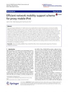
In the second experiment, there are also two nodes in communication. Mobile node A is communicating with a fixed node B, which is behind firewall. Node A is equipped with an 802.11b WLAN and an Ethernet interface, the WLAN interface is always on in this experiment. There is a bi-directional UDP stream between A and B with rate 32kbps and packet size 250 byte, emulating a real-time VoIP communication. The round trip time between A and B is 40ms. Node A at first uses its Ethernet interface, switches to WLAN at some time (by unplugging the Ethernet wireline), and then switches back to Ethernet (by re-plugging the Ethernet wireline). Due to the fact that B is behind firewall, A will not be able to send CoTI to B directly. Hence A will use PNRP-based S/N to deliver the CoTI message. The time-sequence plot of the UDP data received at A is depicted in Figure 9. We observe that with help from the PNRP-based S/N service, the connection is maintained successfully for both handoffs. The handoff latencies are 100ms and 136ms for Ethernet to WLAN and WLAN to Ethernet handoffs, respectively. Using handoff from Ethernet to WLAN as an example, at first A is receiving packets from Ethernet, and then at time 27.59s, A starts the connection maintenance procedure by sending CoTI to B via the PNRP-based S/N, A receives CoT and sends back BU at time 27.64s, then A receives BA at time 27.69s. After that the procedure is finished and A begins to use the WLAN interface to communicate with B. We also observe that the interruption times for the two handoffs are not the same. This is because when switching from Ethernet
12
to WLAN, the operating system needs some time to detect the disconnection of the Ethernet interface (425ms in this experiment, we notice that this period of time is much larger than the handoff latency caused by EMIPv6, hence a very important topic for further research is how to reduce the network detection time) before handoff procedure can be triggered, whereas when switching from WLAN to Ethernet, since the WLAN interface is still available after the Ethernet wire-line is plugged in, more smooth handoff is achieved. Nevertheless, the handoff latencys caused by EMIPv6 are approximately the same in both cases. 350 Ethernet data WLAN data CoTI via PNRP-based S/N CoT and BU BA
345 340
Packet sequence
335 330 325 320 315 310 305 300 26
26.5
27
27.5
28
28.5
29
Time (s) (a)
730 725 720
Packet sequence
715
Ethernet data WLAN data CoTI via PNRP-based S/N CoT BU BA
710 705 700 695 690 685 680 675 49.5
50
50.5
51
51.5
52
52.5
Time (s) (b)
Figure 9. Handoffs with the help from PNRP-based S/N. (a) From Ethernet to WLAN. (b) From WLAN to Ethernet. We also have performed experiments for simultaneous movement with the help of our PNRP-based S/N implementation. The result is similar to that of the second experiment, except that both nodes simultaneously initiate the E2E connection maintenance procedure.
6. RELATED WORK Mobility management is one of the key issues to enable a ubiquitous all-IP wireless Internet. In literature, there has been lots of related work for device location and connection maintenance.
Mobile IP (MIPv4 and MIPv6) [2-3] perhaps is the most influential mobility management scheme. MIP provides mobility support at IP layer. It introduces a home agent in the network. Each mobile node is assigned a global unique home address (HoA). A correspondent node is expected to get the HoA of a mobile node via the existing DNS system. When a mobile node is away from its “home network”, it always registers its current care-of address (CoA) at its home agent in its ‘home network’ (the home agent may be dynamically discovered). The home agent therefore maintains a mapping relationship between the home address and the care-of address of a mobile node. A correspondent node can always send packets to a mobile node via the home agent of the mobile node. In order to improve route efficiency, route optimization is introduced to enable data packet exchange between the communication peers directly. Our design differs from MIP significantly in that we do not need a home agent for either device location or data forwarding. Cellular IP [27], HAWAII [28], and HMIPv6 [29] are three schemes that provide micro mobility support. They utilize the hierarchical structure of the network to localize the address registration and packet routing when the mobile host is roaming within a local network. We note that micromobility is an ability that cannot be provided by pure end-toend mobility schemes. This disadvantage, however, can be alleviated when combining EMIPv6 with some link layer mobility solutions [e.g., 30], since link layer schemes can provide fast handoff support for mobile devices in a homogeneous intra-domain network. Targeting at overcoming some of the drawbacks (such as performance, survivability) of MIP, in [9], the authors proposed a MIP-LR scheme. The idea of MIP-LR is to introduce a service node named HLR (home location register). Before launching a connection to a mobile host, the peer first queries HLR to get the peer’s current IP address. The HLR is not necessarily located at the home network of a mobile node. The authors further introduced translation servers (TS) or quorum consensus (QC) algorithms to reliably locate a HLR [10]. After getting the current address of a mobile node from HLR, the data packet is delivered directly between communication peers without the involvement of HLR. We note that EMIPv6 differs from MIP-LR in that EMIPv6 a self-organizing system whereas MIP-LR needs to deploy the HLR servers. Besides, MIP-LR is targeted for enterprise environment whereas EMIPv6 is for Internet-like environment. HIP (Host Identity Payload) [8] can be considered as a 3.5 layer solution for mobility. It decouples network and transport layers by introducing a statistically global unique Host Identity. In this way the transport connections are bind to Host Identity, not IP address. The mobility issue can therefore be solved by mapping different IP addresses to the
13
unchanged Host Identities. Different from HIP, our observation in EMIPv6 is that, we can resolve the mobility problem by utilizing the addressing architecture of IPv6 without introducing yet another global ID space. TCP-R [5] and Migrate [6] are transport layer approaches to solve mobility for TCP. Both of them extend TCP states and introduce new procedures to maintain connection continuation for TCP during handover. A mobile host always tries to update its current IP address to its peers by using the newly introduced mobility procedure when it moves to a new wireless network. In [31], an extension is proposed for Migrate to support simultaneous movement based on DNS querying. Both TCP-R and Migrate rely on dynamic DNS update to locate a mobile node. We note that relying on dynamic updates in DNS may cause performance issues to the existing DNS system, which relies on extensive caching to perform well. Furthermore, dynamic updates may cause scalability problem if the number of mobile nodes is large and a large number of location update traffic is generated. At application layer, schemes have been proposed for different applications case by case. For example, SIP [32] can be extended to support mobility by re-sending the INVITE message to the peer to re-establish a session when IP address of a mobile host changes. The application level approaches [32-33] do not need to revise the TCP/IP stack (which usually resides in OS kernel), however, they need to re-establish the connections after address change; hence the handoff latency may be large. Recently, several interesting P2P based mobility support schemes have been proposed. ROAM [12] is a scheme based on I3 [34], an overlay Internet infrastructure. Since ROAM is an indirection based approach and I3 is built on P2P, ROAM is flexible and scalable in providing mobility support. However, the end-to-end semantic of Internet communication does not hold anymore (this, however, should be considered as a character instead of a drawback, since one of the design goals of ROAM is to achieve location privacy). In Mobile Tapestry [13], the authors use the publishing and routing mechanism of Tapestry, to provide rapid mobility support, and hierarchical mobility can be provided to group mobile devices by further introducing yet another level of indirection. Both ROAM and Mobile Tapestry use rendezvous points in P2P overlay for data packet delivery. Our scheme differs from both ROAM and mobile tapestry in that we only use P2P overlay for name resolution and certain mobility message delivery, whereas data packet forwarding is still performed at IP layer. We also note that there are several related work on name resolution which are not directly related to mobility management [35-37]. The intentional naming system (INS) [35] uses a descriptive language to describe name (or resource) and a late binding to integrate name resolution and message routing. The purposes of PNRP and INS are
different, with INS is intended to resource discovery under small scale dynamic networks (e.g., several hundred to a few thousand nodes), whereas PNRP is to provide DNS-alike traditional name to IP address mapping in an Internet alike environment. It is a nature step to use the lookup service provided by the current P2P overlays for name resolution, e.g., [36-37]. In this sense, our PNRP approach is similar with these schemes in that our scheme also achieves log(n) hop routing and needs to maintain an application level routing cache. Besides the detailed technical differences (see Section 2) with the existing P2P schemes, a very important characteristic of EMIPv6 is that PNRP is not only for name resolution but also an indispensably part for connection maintenance.
7. CONCLUSION In this paper, we presented EMIPv6, an end-system based mobility management solution, which solves name resolution and connection maintenance in a self-organizing way. A DHT-based PNRP overlay is constructed for name to IP address resolution by considering the heterogeneity of the end systems. And the connection maintenance is performed between communication peers from end to end without relying on additional network components. Moreover, we further construct a PNRP-based S/N service for mobility handling under firewall/NAT or simultaneous movement. By using P2P technology and performing mobility management from end to end, EMIPv6 has the following key features: 1) it is a complete end-system based, selforganizing approach, and does not need to add any new network components into the network core; 2) it does not introduce new namespace, such as home address or host identity, for mobility handling; 3) it can handle complicated mobility scenarios such as mobility under firewall/NAT or simultaneous movement using P2P technology in a distributed manner. We have evaluated the performance of our extended PNRP design via simulation with data measured from real world. We have implemented EMIPv6 in the Windows XP operating system and performed extensive experiments in our testbed. Our experiments and simulation results have convinced us that our scheme fulfills its design goals (i.e., easy to deploy, small handoff latency and efficient data packet delivery, scalable and robust, transparent to application, and secure). Since EMIPv6 does not introduce additional network components, we expect it to be a quick and alternative way to provide IP layer mobility for mobile hosts. There remain some important areas of research along this end-system based approach. First, the benefits of our scheme depend heavily on the participating of users in this PNRP overlay. Hence some incentives should be introduced to attract end users to forward packets for others. Second, our
14
current implementation only works on laptop and desktop computers. We are porting the implementation to small devices such as pocket PC and cellular phones. It should be interesting to further evaluate the EMIPv6 design in these resource constrained, highly mobile devices.
l=4, pareto l=4, uniform
l=6, pareto l=6, uniform
l=8, pareto l=8, uniform
1 0.98
APPENDIX A. Reachability under PNRP-based S/N We study the reachability of a mobility message under PNRP-based S/N. We denote reachability, PR, as the probability that a mobility message sent by a mobile node is successfully received by the destination. Note that due to the constructed short-cut via NHT, a mobility message delivered via PNRP-based S/N can reach the destination within 2 hops. We assume the size of NHT is l=m×n. If a message is received by one of the l neighbors of the destination host, the message will then be forwarded to the destination from this neighbor. For analysis simplicity, we assume that the communication peers maintain their NHT tables periodically, the maintain interval is T. We study the reachability in the following 2 cases. 1. Exponential distribution lifetime Assume the CDF of the lifetime of a node in PNRP is ⎧1 − e −∂x , x ≥ 0 . F ( x) = ⎨ x