Energy and Power Engineering, 2011, 3, 107-112 doi:10.4236/epe.2011.32014 Published Online May 2011 (http://www.SciRP.org/journal/epe)
Energy Efficient Control of Three-Phase Induction Motor Drive Hussein Sarhan Faculty of Engineering Technology, Al-Balqa’ Applied University, Salt, Jordan E-mail:
[email protected] Received March 7, 2011; revised March 25, 2011; accepted March 29, 2011
Abstract Induction motors are extensively used in industrial and household appliances and consume more than 50% of the total generated electrical energy. The need for energy conservation is increasing the requirements for saving the electrical energy. It is therefore important to optimize the efficiency of electrical drive systems under certain operating conditions. This paper proposes a new control scheme based on search method taking advantage of the fact, that at a certain torque and speed (operating point) there is only one value of stator voltage that operates the motor at optimum efficiency. Simulation performed and results are presented. Keywords: Induction Motor Drive, Efficiency Optimization, Slip Compensation
1. Introduction Induction motors are the most used in industry since they are rugged, inexpensive, and are maintenance free. It is estimated that more than 50% of the world electric energy generated is consumed by electric machines. Improving efficiency in electric drives is important, mainly for economic saving and reduction of environmental pollution [1,2]. Induction motors have a high efficiency at rated speed and torque. However, at light loads, motor efficiency decreases dramatically due to an imbalance between the copper and the core losses. Hence, energy saving can be achieved by proper selection of the flux level in the motor [3,4]. The main induction motor losses are usually split into: stator copper losses, rotor copper losses, core (iron) losses, mechanical and stray losses. To improve the motor efficiency, the flux must be reduced, obtaining a balance between copper and core losses. Many minimum-loss control schemes based on scalar control or vector control of induction motor drives have been reported in literature [4-8]. Induction motor drive can be controlled according to a number of performance functions, such as input power, speed, torque, airgap flux, power factor, stator current, stator voltage, and overall efficiency [9]. Basically, there are three strategies, which are used in efficiency optimization of induction motor drive: Simple state control, model based control, and search control. Search strategy methods have an important advantage compared to other strategies. It is comCopyright © 2011 SciRes.
pletely insensitive to parameters changes, while effects of the parameters variations caused by temperature and saturation are very expressed in two other strategies [10-12]. In this paper, an efficiency optimization controller of induction motor drive system, based on searching the value of stator voltage that maximizes the efficiency, is developed. Then, the validity of the proposed controller and the performance of the drive system were analyzed by simulation results. To reduce the slip at light loads and low frequencies, a slip compensator has been introduced.
2. Modeling and Simulation of Drive System The original drive system studied in this paper consists of IGBT-inverter-based AC to AC converter, three-phase squirrel cage induction motor and V f controller. In order to analyze the system performance, all of these components should be modeled (mathematically described). The inverter-based AC-to-AC converter is considered to be an ideal system, where the DC voltage at the input of the inverter has no AC component, and the output voltage of the filter at the output of the inverter has no harmonics. For sinusoidal pulse width modulation SPWM, the ratio of the amplitude of the sinusoidal waveform to the amplitude of the triangular waveform is called the modulation index m , which can be in the range of 0 to 1 [5]. The stator voltage Vs can be defined as: EPE
H. SARHAN
108
Vs mVn
(1)
where Vn = nominal value of stator voltage. The frequency of the stator voltage f equals the frequency of the sinusoidal input waveform fin . f fin
(2)
Varying the modulation index and the sinusoidal waveform frequency will change the RMS value of the stator voltage and frequency, respectively. Equations (1) and (2) constitute the steady-state model of inverter. The controller with V f constant must apply the following function: Kf , 0 f f n m f fn 1,
(3)
where K 1 f n , and f n = nominal frequency. Based on the flux linkages and voltages equations, the electrical and mechanical models of the squirrel cage three-phase induction motor with respect to a synchronously rotating d q coordinates were adopted for simulation [5,13]. The parameters of modeled and simulated induction motor are given in Table 1.
3. Design of Efficiency Optimization Controller The efficiency of the drive system at any steady state operating point can be calculated as: Pm Ps
(4)
Table 2. Optimal stator voltage as a function of load torque and frequency.
Table 1. Induction motor data. Parameter
Value
Stator resistance R1
1.230
Stator Inductance L1
0.006 H
Mutual Inductance Lm
1.172 H
Rotor resistance referred to the stator R2
1.395
Rotor Inductance referred to the stator L2
0.006 H
Nominal voltage Vn
230/400 V
Load Torque, N·m Voltage, V
Frequency, Hz
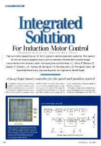
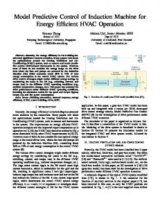
where Pm L , mechanical output power and 3 Ps vsd isd vsq isq , total input power supplied to the 2 stator. To design the efficiency optimization controller based on search method, a matrix, as shown in Table 2, consisting of loads, frequencies and stator voltage values (optimal voltage), which maximize the efficiency, was constructed using MATLAB Simulink model of the studied drive system. The relationship between load torque, frequency and optimal voltage is shown in Figure 1. Based on the data in Table 2 and Equation (4), the relationship between the maximum efficiency, load torque and frequency is shown in Figure 2. For the original system with V f constant controller, the relationship between efficiency, load torque and frequency is shown in Figure 3. The matrix shown in Table 2 was used to form a 2D lookup module (table) in MATLAB, which serves as the main part of the proposed efficiency optimization controller, shown in Figure 4. The output of the controller is the modulation index m, which correspondences the optimal value of voltage maximizing the efficiency under certain operation condition. Simulation results showed that the main disadvantage of the proposed efficiency optimization technique was the increase in slip, especially at light loads and low frequencies, as shown in Figure 5. So, there is a need to compensate (reduce) the slip according to some reference (acceptable) value sref . This can be achieved by increasing the electromagnetic torque
5
10
15
20
25
5
32.8
46.4
57.6
65.6
73.6
10
58.4
86.4
100
116
130.4
15
83.2
116
143.2
176
190.4
20
109.6
151.2
185.6
220
246.4
25
137.6
196.8
236.8
267.2
308.8
30
160.8
222.4
272.8
324
349.6
Nominal output power Pn
4 kW
Nominal power factor cos n
0.850
Nominal frequency f n
50 Hz
35
189.6
276.8
326.4
369.6
400
4
40
220.8
295.2
353.6
400
400
1430 rpm
45
243.2
340
391.2
400
400
0.013 kg m 2
50
272.8
372.8
400
400
400
Number of poles P Nominal rotational speed nn Moment of inertia J
Copyright © 2011 SciRes.
EPE
H. SARHAN
109
Figure 4. Block diagram of efficiency optimization controller.
Figure 1. Optimal voltage as a function of load torque and frequency.
Figure 5. The relationship between slip, torque and frequency for the optimized system.
of the motor by increasing the stator voltage in the optimized system. In this case, the error in slip will be gained and integrated to get the value of compensation voltage that should be added to the voltage in the optimized system. The value of compensation voltage Vcom can be calculated by the following equation: Figure 2. The relationship between maximum efficiency, load torque and frequency.
Vcom K i sref s dt
(5)
where K i = integrating constant. Equation (5) can be realized by adding an integrator as a feedback loop into the optimized drive system. The MATLAB Simulink model of optimization controller with slip compensation is shown in Figure 6.
4. Analysis of Optimized Drive System
Figure 3. The relationship between efficiency, load torque and frequency for the original system.
Copyright © 2011 SciRes.
For quantitative analysis, the efficiency of the optimized system with slip compensation was compared with that in the original system with V/f = constant controller under the same operating conditions by using the simulation results of the MATLAB Simulink model of the drive system, shown in Figure 7. Figures 8-10 are examples of the system behavior under different operating conditions. Figure 8 shows that the efficiency optimization controller increases the efficiency of the drive system, and makes it approximately EPE
H. SARHAN
110
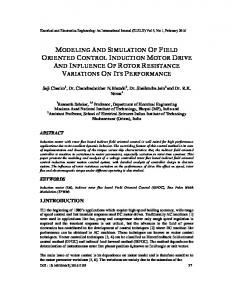
Figure 6. The MATLAB Simulink model of optimization controller with compensation.
Figure 7. MATLAB Simulink model of optimized drive system with slip compensation. Copyright © 2011 SciRes.
EPE
H. SARHAN
111
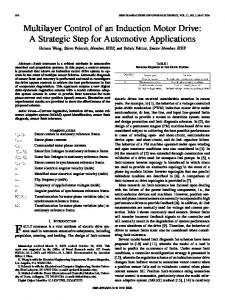
constant for all the range of load. Slip compensation reduces the efficiency of about 4%. Figure 9 shows the relationship between efficiency and frequency at load torque = 10 N.m, form which, it is clear that optimization has not significant effect on the drive system performance. Figure 10 shows the slip response at load torque = 15 N.m and frequency = 5 Hz, from which it is clear that optimization and slip compensation have significant effect on slip.
5. Conclusions
Figure 8. The relationship between efficiency and torque at frequency = 10 Hz.
In this paper, an efficiency optimization controller, based on search method has been developed. The proposed controller manipulates the value of stator voltage that maximizes the efficiency at any given operating point. To reduce the slip to a certain value, a slip compensator has been inserted into the drive system. The suggested technique can be used in variable frequency, variable load electrical drive systems. Based on simulation analysis, it was noticed that the compensated optimized system gives significant results at low frequencies and light loads.
6. References [1]
W. Leonhard, “Controlled AC Drives, a Successful Transfer from Ideas to Industrial Practice,” Control Engineering Practice, Vol. 4, No. 7, 1996, pp. 897-908. doi:10.1016/0967-0661(96)00087-1
[2]
G. C. D. Sousa, B. K. Bose and J. G. Cleland, “Fuzzy Logic Based on-Line Efficiency Optimization Control of an Indirect Vector-Controlled Induction Motor Drive,” IEEE Transactions on Industrial Electronics, Vol. 42, No. 2, 1995, pp. 192-198. doi:10.1109/41.370386
[3]
H. R. Andersen, C. B. Rasmussen, E. Ritchie and J. K. Pedersen, “Efficiency Comparison of Electrical Motors for Energy Optimized Variable Speed Low Power and Low Cost Household Equipment,” 6th European Conference on Power Electronics and Applications, Seville, 1995, pp. 3381-3386.
[4]
F. C. Lin and S. M. Yang, “On-Line Tuning of an Efficiency-Optimized Vector Controlled Induction Motor Drive,” Tamkang Journal of Science and Engineering, Vol. 6, No. 2, 2003, pp. 103-110.
[5]
H. Sarhan and R. Issa, “Modeling, Simulation and Test of Inverter-Induction Motor Drive System with Improved Performance,” Journal of Engineering Sciences, Assiuit University, Vol. 33, No. 5, 2005, pp. 1873-1890.
[6]
F. Abrahamsen, J. K. Pedersen and F. Blaabjerg, “State-of-the-Art of Optimal Efficiency Control of Low Cost Induction Motors Drives,” The Power Electronics and Motion Control Council’96, Budapest, 2-4 Septemper 1996, pp. 163-170.
Figure 9. The relationship between efficiency and frequency at torque = 10 N·m.
Figure 10. The slip response at torque = 15 N·m and frequency = 5 Hz.
Copyright © 2011 SciRes.
EPE
H. SARHAN
112 [7]
I. Kioskeridis and N. Margaris, “Loss Minimization in Induction Motor Adjustable-Speed Drives,” IEEE Transactions on Industrial Electronics, Vol. 43, No. 1, 1996, pp. 226-231. doi:10.1109/41.481429
[8]
I. Kioskeridis and N. Margaris, “Loss Minimization in Scalar-Controlled Induction Motor Drives with Search Controllers,” IEEE Transactions on Power Electronics, Vol. 11, No. 2, 1996, pp. 213-220. doi:10.1109/63.486168
[9]
A. K. Sharma, R. A. Gupta and Laxmi Srivastava. “Implementation of Neural Network in Energy Saving of Induction Motor Drives with Indirect Vector Control,” Journal of Theoritical and Applied Information Technology, Vol. 5, 2008, pp. 774-779.
[10] F. Abrahamsen et al., “Efficiency-Optimized Control of
Copyright © 2011 SciRes.
Medium-Size Induction Motor Drives,” IEEE Transactions on Industry Applications, Vol. 37, No. 6, 2001, pp. 1761-1767. doi:10.1109/28.968189 [11] S. M. Yang and F. C. Lin, “Loss-Minimization Control of Vector-Controlled Induction Motor Drives,” Journal of the Chinese Institute of Engineers, Vol. 26, No. 1, 2003, pp. 37-45. doi:10.1080/02533839.2003.9670752 [12] A. A. Ansari and D. M. Deshpande, “Induction Motor Efficiency Optimization Using Fuzzy Logic,” International Journal of Advanced Engineering and Applications, Vol. 1, 2010, pp. 177-180. [13] O. I. Okogo, “MATLAB Simulation of Induction Machine with Saturable Leakage and Magnetizing Inductances,” The Pacific Journal of Science and Technology, Vol. 5, No. 1, 2003, pp. 5-15.
EPE