link communications [9], [10]. ... and (N â 1) extended TXs (â¢) TXn, n = 2,...,N, connecting to TX1. .... correctly decode log2 (1 + SNRu)-bit information per unit.
1
Energy Efficient Power Control for Distributed Transmitters with ZF-Based Multiuser MIMO Precoding Jingon Joung, Member, IEEE, and Sumei Sun, Senior Member, IEEE
Abstract—Distributed transmitter (D-TX) system with multiple distributed TXs is considered. To support multiple users, the DTX system employs a zero-forcing based multiuser multiple-input multiple-output precoding. An energy efficiency (EE) maximization problem is formulated under constraints on per-user data rate and per-antenna instantaneous transmit power. The latter constraint is to avoid severe distortion of transmit signals at a power amplifier, i.e., the clipping effects. A low-complexity and performance-effective power control method is then proposed by solving the modification of the original, intractable optimization problem. Transmit antenna selection is elucidated with respect to the EE. Numerical results verify the efficacy of D-TX system employing the proposed EE-aware power control and antenna selection with respect to both system EE and outage performance, and also impart the importance of equal power output capability, i.e., equal maximum output power of the distributed TXs, for energy efficient D-TX systems. Index Terms—Energy efficiency, power control, distributed transmitters, power output capability, multiuser MIMO.
I. I NTRODUCTION
E
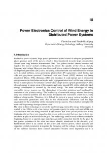
NERGY efficiency (EE) has been studied widely for various wireless communication systems, recently [1]– [8]. On the other hand, to achieve high spectral efficiency (SE), a distributed antenna system (DAS) and a coordinated multipoint (CoMP) transmission technology, which can recover severe path loss and increase coverage, have been employed to multiuser multiple-input multiple-output (MU-MIMO) downlink communications [9], [10]. The SE-maximizing solution, however, does not necessarily achieve the maximum EE. In this letter, we propose a power control method with transmitter (TX) antenna selection to enhance the EE for a distributed TX (D-TX) system. The D-TX system has N multiple distributed TXs, in which TX n has Mn distributed or co-located antennas as illustrated in Fig. 1, and supports a general configuration combining DAS and CoMP. To maximize EE, we compare all maximum achievable EEs obtained from all possible TX antenna sets. To obtain the maximum achievable EE for a given antenna set, D-TXs perform cooperative processing, that is a zero-forcing (ZF)-based MUMIMO linear precoding. The transmit power of D-TX systems employing the cooperative MU-MIMO precoding should be carefully (i.e., jointly instead of individually) managed due to the following issues. • D-TX system has either equal (i.e., P1 = · · · = PN ) or unequal (i.e., there exists n and n′ such that Pn 6= Pn′ ) power output capability (POC). The unequal POC means that D-TXs have dissimilar power amplifiers (PAs) with different clipping levels constraining the maximum The authors are with the Institute for Infocomm Research (I2 R), A⋆ STAR, 1 Fusionopolis Way, #21-01 Connexis (South Tower), Singapore 138632 (email: {jgjoung, sunsm}@i2r.a-star.edu.sg).
TX5
TXN ∗
∗
TX1 ∗
TX4
TX2 TX3
Fig. 1. D-TX system consisting of N transmitters: One central TX (◦) TX1 and (N − 1) extended TXs (•) TXn , n = 2, . . . , N , connecting to TX1 . Users and distributed antenna are illustrated by ‘×’ and ∗, respectively.
•
output power Pn for TX n. The clipping effect increases spectral regrowth and inter-user interferences. Since the transmit power of each D-TX is coupled with one another through the cooperative processing and power allocation variables, EE deteriorates significantly if there are unintentionally high power allocation and consumption at an antenna port located very far from the receiver.
To resolve the issues, we propose an EE-aware power control and antenna selection method. The joint optimization of transmit power and active antenna set, however, is intractable due to the nonlinear, nonconvex objective function and the coupled, nonlinear power constraints. Thus, we consider a suboptimal decomposition approach with two subproblems: i) an EE-aware power allocation subproblem in Sections III and IV, and ii) an antenna selection subproblem in Section V. We first propose an EE-aware power control for a given antenna set which satisfies a per-user data rate constraint and a perantenna instantaneous transmit power constraint. The instantaneous power constraint is a more stringent constraint than an average transmit power constraint (see e.g., [2] and [3]), and it makes the original optimization problem intractable. Thus, the modification of the power allocation subproblem is considered. If there is no feasible power control satisfying the constraints, an outage happens. Based on the achievable EE obtained from the EE-aware power control for a particular antenna set, we can readily select the EE-aware antenna set, which is an essential procedure to improve the network EE. Note that even zero-power transmission consumes overhead circuit power in practice; therefore, the power control does not capture antenna selection in an EE maximization problem. Numerical results verify the potential efficacy of the D-TX systems with the proposed EE-aware power control, and provide informative results regarding the ZF-based MU-MIMO D-TX systems: for example, i) EE-optimal number of active antennas increases as a target rate increases (see Fig. 2(a)); and ii) equal POC achieves higher EE than unequal POC (see Fig. 4).
2
II. S YSTEM M ODEL We consider N TXs, denoted by TXn , where n ∈ N = {1, . . . , N }. One central TX TX1 performs centralized power control for itself and all (N − 1) extended TXs, TXn , n = 2, . . . , N . The extended TXs are connected to TX1 through a noise-free wired backhaul (e.g., optical fiber) for coordinated MU-MIMO communications. Generally, any TX can be a central TX, and any type of network topology can be applied to the D-TX systems according to the network applications. In the network, U user equipments (UEs), denoted by UEu where u ∈ U = {1, . . . , U }, are supported simultaneously by using the same frequency band through MU-MIMO techniques. We assume that all UEs have a single receive antenna1 for simplicity and have the same priority and delay constraint with a proper admission control. PLet us define an antenna index set, M, including M ≤ n∈N Mn distributed or co-located antennas, whose corresponding channels between transmit and receive antennas are independent and identically distributed (i.i.d.). Hence, the channel matrix of the selected antennas from M is full rank. Since at least rank U MIMO channel is required to support U UEs with a ZF-based2 MU-MIMO, M should be greater than or equal to U to perfectly eliminate the interferences. If M < U , we have to schedule the UEs with orthogonal time and/or frequency resources. With enough number of TXs or TX antannas, we assume M ≥ U throughout the paper. III. P OWER A LLOCATION S UBPROBLEM F ORMULATION Denoting a received signal at UEu by yu , its vector form y = [y1 · · · yU ]T is written for the fixed TX antenna set I ⊆ M as √ y = HW p ◦ x + n, (1) where H is a U -by-|I| MU-MIMO channel matrix corresponding to the selected |I| antennas and the U UEs, and |I| is a cardinality of I; W is a |I|-by-U MU-MIMO preprocessing matrix; p , [p1 · · · pU ]T is a U -by-1 power allocation vector whose uth element pu determines a power portion to UEu ; ‘◦’ represents an entrywise product; x = [x1 · · · xU ]T is a transmit signal vector where xu is a transmit symbol to UEu with Gaussian distribution and E |xu |2 = 1; and n = [n1 · · · nU ]T is an additive white Gaussian noise (AWGN) vector whose uth element nu is an AWGN at UEu with a zero mean and a σ 2 variance. The (u, i)th element of H represents a channel p p gain Au,i hu,i consisting of the large-scale fading Au,i (i.e., path loss) and the small-scale fading hu,i between TX antenna i ∈ I and UEu . The ith TX antanna is located at TXπ(i) where π(i) is a mapping function from antenna index i to TX index n ∈ N , i.e., π(i) = n. For the ZF-based MUMIMO, W� is obtained �T from a pseudo-inverse matrix of H as W = w1 · · · w|I| , H + , where wi is a U -by-1 ZF weight vector for antenna i; therefore, HW becomes a U dimensional identity matrix. 1 The results in this letter can be directly extended to the case of multiple receive antennas at UE, if we treat each UE antenna as a virtual user, or if each UE employs receive beamforming or combining. 2 Since a ZF-based method can achieve near optimal SE in MU-MIMO systems if the signal-to-noise ratio (SNR) is high enough [11], [12], we employ it under the high SNR assumption. The assumption is relevant for the D-TX systems which can effectively reduce the path loss.
Using the ZF-based MU-MIMO preprocessing to (1), we derive the received SNR of stream u as SNRu = pu σ −2 . With high input backoff, we assume that a PA input signal is linearly amplified and the PA output signal has a Gaussian distribution [4], and we can further assume that UEu can correctly decode log2 (1 + SNRu )-bit information per unit frequency and time (bits/sec/Hz). In practice, however, the backoff is restricted for the efficient transmission; therefore, there is a clipping on the amplified signals, and Gaussian signaling assumption is invalid. Non-Gaussian signaling causes an SNR penalty and equivalently increase the noise variance from σ 2 to σ b2 = σ 2 + ∆. Accordingly, for any arbitrary signaling, we write the achievable throughput of� UEu over bandwidth Ω Hz as TP(pu ) = Ω log2 1 + pu σ b−2 , ∀u ∈ U, and obtainPthe system throughput per unit time (bits/sec) as TP(p) = u∈U TP(pu ). MIMO system’s power consumption (Watt) corresponding to p and |I| is modeled as PC(p) = f (p) + Po (see [5], [13]), where the transmit power and independent terms Pdependent c are defined as f (p) , i∈I ηi Pi (p) and Po , |I|Pcc + |I|ΩPsp1 + ΩPsp2 + Pfix , respectively. Here, c is a system dependent power loss coefficient which can be empirically measured and obtained, and c > 1; ηi is the efficiency of PA 2 √ at TXπ(i) and 0 < ηi ≤ 1; Pi (p) = wiT p ◦ x is an instantaneous transmit power of the selected TX antanna i of TXπ(i) ; Pcc is radio frequency (RF) circuit power consumption which is proportional to the number of RF chains, i.e., |I|; Psp1 and Psp2 are signal processing related power consumption per unit frequency and Psp1 is proportional to |I|; and Pfix is a fixed power consumption which is independent of Pi (p) and Ω, for example, a part of power consumption at a power supply and a cooling system. We now formulate a power allocation problem to maximize EE (bits/Joule) for given I as follows: p∗ = arg max EE(p)
(2a)
p∈RU ×1
� (2b) s.t. Ω log2 1 + pu σ b−2 ≥ Ru , ∀u ∈ U T√ w p ◦ x 2 ≤ Cπ(i) , ∀i ∈ I, (2c) i � where EE(p) = TP (p) PC (p); the inequalities in (2b) follow the per-user rate constraints with a target rate Ru of UEu ; and (2c) is a per-antenna instantaneous power constraint, which is induced by the distributed TXs with different POC of PAs, i.e., clipping level Cn . The transmit power of each antenna, i.e., the output power of each RF-chain, is limited by Pn /Mn to cover the case when all Mn antennas of TXn are selected for the MU-MIMO and to fulfill the radio regulations. � Thus, each PA is designed to satisfy that Cn ≤ Pn Mn . Directly solving (2) is formidable due to the nonlinear, nonconvex objective function in (2a) and the coupled nonlinear3 constraints in (2c) over {pu }. To obtain a tractable power control method, modification or relaxation of (2) is inevitable. In the letter, we decide to modify (2) to obtain a tractable, closed form expression of p. √ that the left hand side of (2c) is power of sum of pn . On the other hand, an average transmit power constraint in [2] and [3] is a linear constraint, √ i.e., sum of power of pn , which makes the EE maximization problem be solvable, yet an instantaneous clipping effect at PA is not considered. 3 Note
3
0
S OLUTION
We first consider maximizing the EE lower bound instead of the actual EE in (2). To this end, we define a common power scaling factor α and a relative power portion pu of P UEu , such that pu = αpu , ∀u ∈ U and u pu = 1. We then derive the EE lower bound and define it as a function of α and p = [p1 · · · pU ]T as follows: � � ΩU log2 1 + αmin{pu }b σ −2 u EE(p) ≥ P , EEL (α, p). (3) √ 2 α i∈I ηci wi p ◦ x + Po
Substituting the objective function in (2a) with the EE lower bound in (3), and using α and p to (2b) and (2c), we modify the original optimization problem (2) as {α, p} =
argPmax EEL (α, p)
α, p,
u
(4a)
pu =1
� , αL (p) (4b) s.t. α ≥ max γu p−1 u u∈U � � p −2 α ≤ min Cπ(i) wiT p ◦ x , αU (p), (4c) i∈I
where γu , σ b2 (2Ru /Ω − 1) is minimum-required power for Ru , and (4b) and (4c) follow (2b) and (2c), respectively. The modified problem (4) enables us to design the energy efficient systems by simply optimizing α if the optimal power ratio vector p is given. This is because the problem structure of (4) is now well-defined, namely the modified objective function (4a) is quasi-concave4 (unimodal) over α and the one-dimensional feasible set is bounded by αL (p) and αU (p). However, to optimally determine p remains still unresolved. One method what we could directly consider to tackle this issue is an iterative approach, in which α and p are updated alternately, yet convergence and complexity issues arise. In this letter, we determine pu to be proportional to the minimumrequired power for Ru , i.e., P γu , and denote it by peu . After the normalization to satisfy u peu = 1, we have !−1 X peu = γu γk , ∀u ∈ U. (5) k∈U
Though the strategy in (5) is heuristic, it is appropriate with respect to the fairness of power allocation to users who require different target rates. For given p by pe = [e p1 · · · peU ]T , problem (4) maximizing the EE lower bound is rewritten with respect to α as ΩU log2 (1 + c1 α) (6a) c2 α + Po α s.t. αL ≤ α ≤ αU , (6b) p P where c1 , minu {e pu }b σ −2 ; c2 , i∈I ηci |wi pe ◦ x|2 ; αL = p � P σ b2 k∈U γk ; and αU = mini∈I Cπ(i) |wiT pe ◦ x|−2 . Note that all c1 , c2 , αL , and αU in (6) are constant values for given e Now, we can readily find the maximizer αo which makes p. the first derivative of the objective function (6a) to zero as � � � �� � 1 1 c1 Po αo = exp 1 + W − + −1 , c1 exp(1) c2 exp(1) α∗ = arg max
4 It can be readily proved by using the facts that a log function is concave and that the denominator of EEL (α, p) is a monotonically increasing function over α within a positive convex domain.
10
A 0.2
0.1
SE-C-TX EE-C-TX EE-D-TX
B 0 2
B
−1
10
outage
AND I TS
energy efficiency, Mb/J
IV. M ODIFIED P ROBLEM
4
6
8
10
number of antennas, M
(a) Energy efficiency
12
10
A
−3
10
−4
10
−5
14
C-TX
−2
10
2
C-TX
SE-C-TX EE-C-TX EE-D-TX 4
6
8
10
number of antennas, M
12
14
(b) Outage
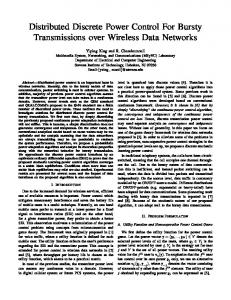
Fig. 2. Performance evaluation over the number of active antennas, M , when {R1 , R2 } = {40, 60} Mbps (A) and {R1 , R2 } = {50, 70} Mbps (B).
where exp(·) is an exponential function and W(·) denotes the Lambert W function that satisfies q = W(q)eW(q) . Considering feasible region (6b), we get the optimal feasible solution of (6) as α α∗ = [αo ]αUL , (7) where [x]ba takes x if it is between a and b, and the closest boundary a or b otherwise. If the optimization set is infeasible, i.e., αL > αU , an outage happens and at least one UE cannot be supported. Remind that αL follows the minimum-required power to support all users’ target rates in (2b), while αU is desired to fulfill all antennas’ instantaneous transmit power limitation in (2c) and it is also restricted jointly over all selected antennas due to the ZF property as shown in (4c). V. A NTENNA S ELECTION S UBPROBLEM Fig. 2 shows EE and outage performance over M when we activate all M antennas. Two users are supported by ZF-based MU-MIMO, and equal POC is considered, i.e., Pn = 46 dBm, ∀n (refer to Section VI for other parameters). Two collocated-TX (C-TX) systems are compared. SE-CTX selects the TX antannas to maximize SE and uses the maximum available transmit power, while EE-C-TX focuses on EE maximization like the proposed D-TX system, EE-DTX. We observe that the EE highly depends on the number of active antennas, and that the EE-aware antenna set I ∗ depends on the target rate. From the observation, it is clear that optimization of antenna set I is a crucial procedure for EE enhancement. We recall the original problem formulated as i h {I ∗ , p∗ } = arg max EE (p) I , s.t. (2b) and (2c). (8) I⊆M,p
For a given I, we can readily perform a fair and EE-aware power control with pe∗ = [e p∗1 · · · pe∗U ]T where pe∗u = α∗ peu from (5) and (7). Note that EE becomes zero if there is no feasible pe∗ satisfying (2b) and (2c). Eventually, a remaining problem is to find I ∗ , which is a combinatorial optimization problem to select I with the cardinality U ≤ |I| ≤ M . Various suboptimal searching algorithms can be applied to solve the combinatorial problem of (8). We, however, defer devisal of searching algorithm to solve the combinatorial problem to future work, and at this moment, we emphasize that the combinatorial search becomes more tractable due to our closed-formed pe∗u . No matter what type of searching algorithms we employ, we can combine pe∗ with the searching
4
1.0
0.5
0.2
0.7
0.1
optimal: EE(p∗ )
0 16
22
28
34
P2 dBm
40
46
0.4 16
heuristic: EE(pe∗ )
(a) Energy efficiency
22
28
34
P2 dBm
40
46
(b) Outage
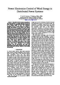
Fig. 3. Comparison between optimal and heuristic power control methods.
algorithm without any confliction. However, the optimality loss from pe∗u causes inevitable performance degradation. To quantify the performance degradation, EE and outage of D-TX system are evaluated with p∗ and pe∗ for a small-scale network (U = 2, N = 2, M1 = 1, M2 = 1, and P1 = 46 dBm). We find p∗ for the small network via two-dimensional line search, exhaustively. Remind that it is formidable to solve (2) and find p∗ in a general network setup. From Fig. 3, it is observed that EE (pe∗ ) follows the same trend as EE (p∗ ). Furthermore, though there is nontrivial EE gap (no greater than 10%), the outage performance gap is negligible. VI. P ERFORMANCE E VALUATION
AND
D ISCUSSION
In this section, we evaluate EE and outage performance with the proposed power control. Simulation parameters are summarized as follows. The path loss is modeled as Au,i = G − 128 + 10 log10 (d−ν u,i ) in dB scale, where G includes the transceiver feeder loss and antenna gains, d−ν u,i is the path loss for the distance du,i between TXπ(i) and UEu , and ν is a path loss exponent. The small-scale fading is modeled as Rayleigh fading with a zero mean and a unit variance. In our simulation, we set G = 5 dB, ν = 3.76, σ b2 = −174 dBm / Hz, Cn = Pn /Mn , Ω = 5 MHz, R1 = 40 Mbps, and R2 = 60 Mbps. Power related parameters are as follows [5], [13]: c = 2.63, Pcc = 66.4 W, Pfix = 36.4 W, Psp1 = 1.82 µW / Hz, and Psp2 = 3.32 µW / Hz. The efficiency of all PAs is assumed to be sustained by 30% through a PA selection [5], i.e., ηi = 0.3, ∀i. For D-TX network setup with two UEs and four TXs, we assume that i) all TXs have two co-located antennas, i.e., M = 8; ii) the extended TXs, TX2 , TX3 , and TX4 , are located at 0.5 km from the central TX1 and they are equidistant from one another; and iii) UEs are distributed uniformly within 0.8 km from TX1 . Equal and unequal POCs are compared. For the unequal POC case, denoted by ‘uPOC,’ we fix P1 by 46 dBm and vary P2 = P3 = P4 . For the equal POC case, denoted by ‘e-POC,’ P4 the maximum output power of all TXs is the same as n=1 Pn /M . Figs. 4(a) and (b) show EE and outage performance, respectively. From the numerical results, we verify three remarks: i) The proposed EE-aware power control and antenna selection methods improve EE. ii) D-TX system outperforms C-TX in terms of both EE and outage performance. iii) Equal POC outperforms unequal POC in terms of both EE and outage performance. From the remarks, we can surmise that the most promising system for both EE and outage is an EE-maximizing D-TX system with equal POC.
0
10
0.4 −1
10
0.3
outage
heuristic: EE(pe∗ )
0.3
energy efficiency, Mb/J
optimal: EE(p∗ )
outage
energy efficiency, Mb/J
0.4
0.2
SE-C-TX: e-POC EE-C-TX: u-POC EE-D-TX: u-POC EE-C-TX: e-POC EE-D-TX: e-POC
0.1 0
16
22
28
34
P2 = P3 = P4 dBm
40
−2
10
−3
10
−4
46
10
16
SE-C-TX: e-POC EE-C-TX: u-POC EE-D-TX: u-POC EE-C-TX: e-POC EE-D-TX: e-POC 22
(a) Energy efficiency
28
34
P2 = P3 = P4 dBm
40
46
(b) Outage
Fig. 4. Numerical results when R1 = 40 Mbps and R2 = 60 Mbps.
VII. C ONCLUSION In this letter, we have considered a D-TX system employing a ZF-based MU-MIMO linear precoding. A simple, heuristic power control method has been proposed to improve system EE under constraints on per-user target rate and on per-antenna instantaneous transmit power. Numerical results have highlighted the importance of antenna selection in terms of EE, and confirmed that the proposed multiuser power control with antenna selection improves both EE and outage performance. R EFERENCES [1] H. Bogucka and A. Conti, “Degree of freedom for energy savings in practical adaptive wireless systems,” IEEE Commun. Mag., vol. 49, pp. 38–45, Jun. 2011. [2] C. Isheden, Z. Chong, E. Jorswieck, and G. Fettweis, “Framework for link-level energy efficiency optimization with informed transmitter,” IEEE Trans. Wireless Commun., vol. 11, pp. 2946–2957, Aug. 2012. [3] D. W. K. Ng, E. S. Lo, and R. Schober, “Energy-efficient resource allocation in multi-cell OFDMA systems with limited backhaul capacity,” IEEE Trans. Wireless Commun., vol. 11, pp.3618–3631, Oct. 2012. [4] J. Joung, C. K. Ho, and S. Sun, “Spectral efficiency and energy efficiency of OFDM systems: impact of power amplifiers and countermeasures,” IEEE J. Sel. Areas Commun., vol. 32, no. 12, pp. 1–13, Dec. 2014, (early access articles). [5] —-, “Power amplifier switching (PAS) for energy efficient systems,” IEEE Wireless Commun. Lett., vol. 2, pp. 14–17, Feb. 2013. [6] J. Joung and S. Sun, “Power efficient resource allocation for downlink OFDMA relay cellular networks,” IEEE Trans. Signal Process., vol. 60, pp. 2447–2459, May 2012. [7] G. Miao and J. Zhang, “On optimal energy-efficient multi-user MIMO,” in Proc. IEEE Global Commun. Conf. (GLOBECOM), Dec. 2011. [8] C. Jiang and L. J. Cimini, Jr., “Downlink energy-efficient multiuser beamforming with individual SINR constraints,” in Proc. IEEE Mil. Comm. Conf. (MILCOM), Nov. 2011, pp. 495–500. [9] R. Zhang, “Cooperative multi-cell block diagonalization with per-basestation power constraints,” IEEE J. Sel. Areas Commun., vol. 28, pp. 1435–1445, Dec. 2010. [10] R. W. Heath, T. Wu, Y. H. Kwon, and A. C. K. Soong, “Multiuser MIMO in distributed antenna systems with out-of-cell interference,” IEEE Trans. Signal Process., vol. 59, pp. 4885–4899, Oct. 2011. [11] J. Joung, E. Y. Kim, S. H. Lim, et al., “Capacity evaluation of various multiuser MIMO schemes in downlink cellular environments,” in Proc. IEEE Int. Symp. on Personal, Indoor and Mobile Radio Commun. (PIMRC), Sep. 2006. [12] J. Lee and N. Jindal, “High SNR analysis for MIMO broadcast channels: dirty paper coding versus linear precoding,” IEEE Trans. Inf. Theory, vol. 53, pp. 4787–4792, Dec. 2007. [13] J. Xu, L. Qiu, and C. Yu, “Improving energy efficiency through multimode transmission in the downlink MIMO systems,” EURASIP J. Wireless Commun. Netw., vol. 2011, pp. 1–12, Dec. 2011.