Engineering Tools to Support Interoperability in the Development and Maintenance of Heterogeneous Distributed Real-Time Control Systems A.S. Prayati*, A.P. Kalogeras**, K. Lorentz***, S. Koubias*
[email protected],
[email protected] ,
[email protected] ,
[email protected]
*Applied Electronics Laboratory, Departement of Electrical Engineering & Computer Science, University of Patras, 26500 Patras, Greece, tel.: +302610997299, fax: +30261997333 **Industrial Systems Institute, University Campus, University of Patras, 26500 Rion, Patras, Greece, tel.: +302610910308 ***Otto-von-Guericke IAF, University of Magdeburg, Postfach 4120, 39016 Magdeburg, Germany, tel.: +49 391 6711829
Abstract Some of the basic innovative trends of the industrial environment, today, are the shift from centralized control architectures to distributed systems, as well as the increasing degree of heterogeneity. These features impose the need for special software tools that support the design of control applications in a homogeneous and interoperable way, as well as their distribution to the interconnected participating industrial devices. The utilisation of the internet and the provision of e-services to the industry will also lead to the distribution of management functionalities in addition to control code distribution. Such an evolution requires both a new model for industrial devices as well as a design and deployment tool that will make possible the distribution of functionalities to industrial devices. This paper presents the state-ofthe-art considering distributed industrial system design and concludes with a specification of distributed systems, enabling the incorporation of novel advanced functionalities.
1
1. Introduction The industrial environment has experienced a considerable shift from centralized control architectures and systems to distributed systems. Two main elements have led to this shift: industrial communications and smart industrial devices. Industrial communications at the lowest field level made spatial distribution in the industrial environment possible from an economical and technological point of view, replacing pointto-point connections with bus connections while special protocols guaranteed real-time or critical-time data transfer characteristics. On the other hand, smart industrial devices made possible the distribution of control application code that used to reside in central control points. In addition to the increased degree of distribution in the industrial environment, the heterogeneous nature of real-time control applications imposed the need for special software tools that would make it possible to design the control application in a distributed way as well as distribute it to the interconnected participating industrial devices. Standardization work is being done considering both the industrial device structure as well as its algorithmic behavior, so that control code reuse is promoted and device interoperability is achieved. In this context, the IEC 61499 standard [1] introduced a Function Block [2] based control algorithm model for industrial devices, while the IEC 61804 standard [3] proposed a methodology for the design of modular, reusable, distributed Industrial Process and Measurement Control Systems (IPMCSs). The ubiquity of the Internet infrastructure is currently resulting in major changes in the development and maintenance of IPMCSs. The integration of the internet into the industrial communication hierarchy is leading to a further increase in industrial system distribution, while it is expected to provide novel, extremely dynamic functionalities related to industrial systems. The support of Internet protocols by major industrial fieldbuses, as well as the industrial Ethernet, will make the integration of the Internet down to the industrial device feasible, leading to the opening of a new market for the provision of new electronic services to the industry relevant for instance to system maintenance and reconfiguration. The utilisation of the internet and the provision of e-services to the industry will also have impact on industrial system distribution, since it will lead to the distribution of management functionalities in addition to control code distribution. Thus, the industrial system configuration could be done in a fully
2
distributed way, and industrial devices could be self-configured taking into account their participation in the overall industrial environment and utilising their web connectivity. Such an evolution requires both a new model for industrial devices as well as a design and deployment tool that will make possible the distribution of functionalities to industrial devices. This paper presents the state -of-the-art considering distributed industrial system design and concludes with a specification of distributed systems, enabling the incorporation of novel advanced functionalities.
2. Related Work Due to the economic impact of industrial distribution, several approaches exist that are related to the distributed industrial system design. This section presents an overview of the technological state-of-theart in this area as represented by dominant and emerging technological solutions. The Siemens PROFInet approach The Siemens approach to distributed automation is related to the PROFInet standard [4]. The PROFInet concept represents the basis of a PNO-wide automation and engineering system. PROFInet defines the minimum number of common points that are required for an open manufacturer-independent automation system. Based on the existing product range, it enhances the functionality that is required for a distributed automation. The openness of the PROFInet approach is based on the utilization of well established accepted market standards. Its automation object model is defined according to the Microsoft COM/DCOM standard. Objects communicate based on TCP/IP and the DCOM wire protocol and are handled through HMI using Microsoft OLE, ActiveX. According to the PROFInet concept, systems are divided into technological modules. Each module consists of mechanical and electrical components as well as the control software. The control software can be programmed either in a language regarding to respecting the IEC 61131-3 standard [5] or a in a proprietary manufacturer-provided language in subject to the manufacturer of the specific component. An engineering tool, namely iMap, is provided to allow, among others, the connection of the modules and to form the automation system by joining distributed applications together. Once the control logic is programmed in the devices and the software components are created for each PROFInet component, they can be interconnected graphically through iMap’s graphical interface, without programming the communication functionality manually. The engineering process consists of the following steps:
3
°
Configuration of the device is performed by manufacturer-specific engineering tools and is not part of iMap. Device configuration may also imply parameterisation or even programming of the device.
°
Data grouping and wrapping in components. All engineering information, required during application development process, is gathered and organized in components.
°
The components are described in a general XML [6] formatted file and optional data formats like COM DLLs.
°
The information included in the XML files is used by the iMap engineering tool in order to install and configure the communication of the created components.
°
Once the previous steps are concluded, all data produced by iMap is downloaded into PROFInet devices. Implementation of interfaces and event connections is open for the designer to decide. Real-timeliness
is not closely considered by iMap tool since Function Blocks are supposed to have zero start and finish times, as well as execution time, apart from the DELAY Function Block component. This particular feature deprives the engineer of real-time handling fle xibility. The IDA Approach A second approach is formed by the Interface for Distributed Automation (IDA) group, founded in the beginning of the year 2000 to work out a standardized specification for the modularisation of a machine into non-order-related functional units and machine modules that can be reused flexibly in different projects. The driver of this initiative is the reduction of costs for start-up, maintenance or extension of a machine during system planning, construction and manufacturing automation solutions. Engineering and runtime are the two main phases that rule today’s automation systems. Engineering describes the definition of a specific automation solution, which is formed in a structured way using the IDA Engineering Objects. The IDA Engineering Framework defines the technical rules how to form IDA Engineering Objects and how they work together in this application. The Engineering Objects are transformed into IDA Runtime Objects of the runtime level to be executed. The execution of the Runtime Objects and the communication between them works using the mechanisms of the IDA Runtime Environments.
4
The IDA specification [7] defines an infrastructure for open heterogeneous automation applications in modular distributed structures and comprises four essential conceptual areas. °
An object-related software model for mapping an interoperable engineering and runtime architecture.
°
A continuous system-independent connection layer for all classes of communication from the I/O via the control system up to the management and the integration of channels for safety technology based on Ethernet TCP/IP.
°
XML-based devices and functional description for an exchange of device-specific and applicationdependent configuration independent of manufacturers and technologies.
°
A standardized browser-based human machine interface for all components of a heterogeneous automation based on the use of web technologies. Schneider Electric has developed the first engineering tool for the configuration of IDA applications.
The tool for designing the logical network topology is integrated into the Microsoft Visio Framework. It serves the management of IDA applications, the definition of network variables, the consistency of data, as well as documentation, including the definition of communication domains and that of the Publish/Subscribe variables for each domain. A major characteristic of the tool is its openness, the use of XML for the exchange of data with other tools and on the option of integrating other programs. The Lon Ap proach Another engineering tool is the LonMaker Integration tool [8]. It is an integrated software package for designing, installing, configuring, operating and maintaining LonWorks networks. It is based on Echelon’s LNS Network Operating System, which is the network management system for LonWorks networks, utilising a client-server architecture in order to easily set-up, change or reconfigure a LonWorks network. LNS supports multiple platforms and allows multiple users to simultaneously install devices, make repairs or perform diagnostic tasks, thus maximizing accessibility and reducing complexity with reference to handling directory management and routing of services. LonMaker matches the underlying client-server architecture with a Microsoft Visio graphic al user interface, that may be used for the design and commissioning of a distributed control network as well as an operational and maintenance tool. The Visio interface provides a CAD-like environment for the design of a control system. The designer may use single devices, function blocks and connections, or complete systems with nested subsystems. The overall control system design is stored in the LNS database and the
5
control network is configured either through a PC or a special Design Manager DM-20/21, which is a simple Neuron chip based device, with network management capabilities. It is essential to point out here that the Function Block concept used by LonMaker is proprietary and is not IEC61499 compliant, making the design tool fieldbus specific. The HCNet Approach Another tool for the programming of a distributed system is HCNet [9]. The objective of HCNet is to create a software tool that automatically distributes an existing control application among the decentralised components in the field and find the best communication between these components. It is, therefore, beneficial to divide an automation system into reusable and small intelligent units, by means of which, the customised system can be built. The units are called mechatronical units and in addition to mechanical and electrical components they consist of a control device. Each mechatronical unit can be programmed and tested stand-alone whereby the interface of a mechatronical unit are I/O data. The HCNet concept is based on intelligent components i.e. the WAGO-I/O-SYSTEM 750 with the programmable fieldbus controller and other. The applications of the intelligent components are programmed in accordance to IEC 61131-3. In the HCNet concept, the main program is written for the application without consideration of the hardware structure. The HCNet analyses the program regarding data dependence and control flow, distributes the program to the relevant controllers and realises the communication between the components. Communication connections are implemented by means of Function Block calls, existing in the programs of each component. The ETS Approach Finally, ETS presents a software package that may be used for the (off-line) design, as well as the (online) configuration and diagnostics of EIB network installations [10]. The user creates and designs an installation project in ETS, based on product templates provided by the manufacturer of embedded EIB components. A special ETS toolkit allows manufacturers to create such templates and export them as "product database" for import and use in the ETS project design tool. A graphical interface is provided to allow the design of an installation project. The ANubis initiative defines open standards and specifications for protocols, API's and Object Models. ANubis aims to exploit and leverage established or promising new standards.
6
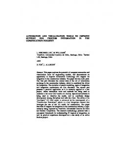
As appears from Figure 1 only the fieldbus specific approaches, namely iMap and LonMaker, generate source code. Even though some specific ations use proprietary solutions, there is a clear trend for a common application representation and device description to support the distributed control application development phase, as well as the system runtime phase. Such generic models are mandatory, as systems tend to be more heterogeneous and complex in nature. These features impose a need for a standardized and formal design trajectory that allows the analysis and design of distributed real-time control application requirements. Moreover, complexity adds a lot of overhead as far as system maintenance is concerned,
iMap
XML
source
IEC61499
DLL
code
XML
-
neuron LonMaker
IEC61131
fieldbuses
Supported
n
online offline
Visio GUI
-
-
-
LonWorks
offline
FBD
proprietary
proprietary -
templates
technologies
IEC61131
compliant EIB
offline
FBD
-
HCNet
web
proprietary
XIF C
Profibus online
x compliant
(2000)
x
FBD IEC61499
IDA
Configuratio
offline ActiveX
(2001)
Openness
HMI
support
Graphical
Output
Input file
making the need for tool support during the whole life cycle of the system imperative.
-
offline -
GUI
online
Figure 1: A partial taxonomy of the IDE tools
The IEC 61499 Standard In 1990, the IEC61499 standard was introduced [1], defining the Function Block concept in its final form. Its predecessor was proposed by the IEC61131-3 standard [5]. According to IEC61499, the requirements for a common field device description are set and the Function Block construct constitutes the main
7
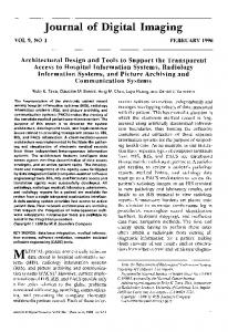
building block of industrial control system applications. The IEC 61499 defines an event driven state machine control of execution. Function blocks are defined by specifying the interfaces, the execution control chart, and the internal algorithms. The specification IEC 61499 Part 1 defines a generic architecture for distributed industrial process and control systems. In the context of this specification, an application is defined as a function block network. The nodes are the function blocks (or sub-applications) and their parameters while the network edges are data connections and event connections. A methodology is also defined, to be used by system designers to construct distributed control systems. IEC 61499 neither specifies implementation rules for the algorithm nor the programming language to be used. Consequently, the algorithm can be expressed in any programming language. It can access input and output variables as well as internal variables to produce new issues of output variables. The IEC 61804 standard In order to support the automatization requirement mentioned above, the evolving standard IEC61804, in 1993, defined the basic concepts and a methodology for the design of modular, re-usable, distributed IPMCSs [3]. The IEC61804 standard, based on IEC61499, provides a new generation Engineering Support Systems (ESS) specification to support the whole life cycle of IPMCS applications. The ESS allows the engineer to analyse the plant diagram, to extract the control requirements, to define the basic functionality and interaction, to design the application in a Function Block Diagram and to assign the functionality into the physical resources. The development phases shown in
Figure 2 are described below. The Process Flow Diagram (PFD) represents the main mechanical units, the piping between these units, the remote transmitters and actuators. The control functions are derived from the PFD and together with all other control from the extended Piping and Instrumentation Diagram (PID). In the next step, the control functions are described in detail and partitioned in hierarchical levels, composing the Control
8
Hierarchy Diagram (CHD). The lowest layer is composed of the control functions interacting with the transmitters and actuators. The upper la yers are composed of control functions coordinating lower layer control functions. The documentation of the control functions generates sets of functional requirements, which are graphically represented by means of IEC61499 Function Blocks and from the Functional Requirements Diagram (FRD). The Function Blocks of the FRD are distributed to the system devices and implemented to HMI, PLCs and MCCs.
to measure fooling up
to cool water
to control the level
Folio 1 : to measure the fooling up
Folio 2 : to cool water
to measure fooling up
to protect the pumps
to control the pumps
2 Extended P&ID
AFB AFB AFB
AFB
Folio 3 : to feed the pumps with water
to cool water
AFB
AFB
AFB
AFB
to protect the pumps
to control the level
AFB
AFB
Folio 4 : to control the pumps
AFB
AFB AFB
to control the pumps
AFB
AFB
AFB
3 Control hierarchy Diagram EFB AFB 2/3
EFB
EFB
AFB pump 3
AFB pump 2
AFB pump 1 to control the pumps to feed the pumps with water to meaure the fooling up to cool the water
1
Process Flow Diagram
4
Functional Requirement Diagrams
Figure 2: Development phases
3. Industrial Distributed System Specification The industrial distributed environment is characterized by a high degree of heterogeneity. Different devices, provided by different vendors, need to interoperate, communicating over different communicating protocols respecting special data transfer requirements. Different control applications involving industrial devices need to be distributed and executed taking into account the available resources and communication aspects. Finally, different functionalities relevant to such engineering aspects as maintenance, configuration and re-configuration need to be appropriately addressed taking into account user specifications and adding value to the overall system. A total life-cycle approach is required in order to take into account all the above factors and resolve their interdependencies. This, in turn, leads to the need for special engineering tools that must
9
respect the different aspects of the industrial environment and which will utilize the dominant and emerging technological solutions so that novel high added value services are provided to the industry resulting in a more flexible and dynamic environment. The ultimate goal achieved by an industrial distributed system is the total distribution of all its functionalities among the participating and interconnected devices. This means that both control algorithms and management-related functionalities are appropriately distributed, taking into account the device resources utilizing appropriate technological solutions. Such a system requires an integrated communication architecture, which unifies the different special industrial communication protocols, the enterprise intranet and the Internet. The first step towards the above-described system involves its design and development. The design phase of the system is crucial since it should take into account all the different requirements that the heterogeneous system components impose. In order to resolve the induced heterogeneity, an appropriate engineering tool for the design should be used, utilizing the prevailing standards. A standard interface for the exchange of information between the different system components and the tool is required. XML provides a prevailing standard that is suitable for this purpose. The basic function of the tool during the design phase is relevant to the distribution of the overall control application among the interconnected industrial devices and control points e.g. controllers, computers etc. For purposes of code reuse and appropriate distribution a device model is required that would mainly address the algorithmic behavior of industrial devices. The IEC 61499 presents such a standard defining a Function Block based algorithmic model for industrial devices. In this context, the engineering tool would allow the appropriate allocation of the code modules that should be deployed in each industrial device. Following the control application distribution among the different industrial system parts, the system initial configuration should take place. The engineering tool should provide appropriate services to generate source code in a widely accepted object-oriented language and embed this code to the industrial device. Such a language could well be Java [11], permitting the utilization of the generated source code by each device and alleviating the engineering tool from the need of generating object code taking into account the different industrial device resource information. The download of the source code to the industrial devices, the creation of the needed objects and the initialization of the control code application modules residing on each device, marks the conclusion of the configuration phase.
10
The described functionalities of the engineering tool are toped by a graphical interface, allowing the design and distribution of the control application in a user-friendly and flexible way. The tool is operating off-line, and provides all needed services for the system initial configuration. In order to allow for a total system distribution, in addition to the control application distribution, the engineering tool should provide distribution of management functionalities as well. Embedding management functionalities to industrial devices would in turn mean that each single device would be able to operate without the need of supervision of any kind, which would lead to a fully distributed environment. The above concept is extremely innovative, since the industrial environment utilizes the engineering tool during the initial configuration phase, while the industrial devices can operate without the need for any kind of supervision henceforth. This concept requires some alterations to the device model allowing for the incorporation of management functionalities. The overall approach will give new dynamic capabilities to the industrial environment, since the incorporation of management functionalities to devices will make it possible for them to be selfreconfigured and self-maintained. An appropriately configured industrial device should utilize the internet integrated infrastructure and check for the existence of a new version of the vendor provided device function code and download it from the vendor internet site. On the other hand vendors could utilize this new concept in order to provide novel e-services to the industry undertaking the goal of mainta ining for instance their devices. The presented system increases the degree of integration and distribution in the industrial environment, is based on prevailing and emerging standards, is vendor and platform independent and addresses the industrial environment problems in a unified way following a total life-cycle approach starting from design and configuration through maintenance and re-configuration.
4. Conclusions The study and categorization of existing engineering tools for distributed heterogeneous in dustrial systems development revealed the basic characteristics such a tool must have in order to fulfill the requirements of the current demanding automation control real-time systems. As concluded by this survey, an engineering tool is needed for the support of the distributed system life cycle, from application design and development to system validation and maintenance. The tool must receive information for the system
11
components in a standardized format in XML, it should support a graphical representation using the Function Block construct as defined in the IEC61499 standard, it should generate device specific source code. The source could be in a widely used object-oriented language like Java, or another format that will be further consist the input to a fieldbus specific programming tool e.g. Profibus / Lonworks). An important characteristic not implicitly treated by the existing solutions is real-timeliness.
5. References [1]
IEC 65/240/CD (61499): Function Blocks for Industrial Process Management and Control Systems Part 1: Architecture Public Available Specification
[2]
ISA/ IEC SP50 Committee Draft Standard for the User Layer
[3]
IEC Committee No.65C, “IEC61804 General Requirements Specification”, IEC Draft 2000
[4]
PROFInet – Architecture Description and Specific ation, V 1.0, PNO, August 2001
[5]
Standard IEC 1131-3 (1993). Programmable controllers: programming languages. IEC TC65/SC65B
[6]
Extensible Markup Language (XML) 1.0 (Second Edition), W3C Recommendation, 6 October 2000
[7]
iDA - Architecture Description and Specific ation, V 1.0, November 2001
[8]
Echelon: www.echelon.com
[9]
Wago legt HCNet auf Eis, in: SPS-Magazin, 4+5 2002, News, TeDo-Verlag GmbH, 2002
[10] EIB Association: www.eiba.com/home.nsf [11] E. DOUGLAS JENSEN , ANDY WELLINGS, RAY CLARK, AND DOUG WELLS, “The Distributed RealTime Specification for Java: A Status Report”. Proc. Embedded Systems Conference, 2002
12