Computing and Informatics, Vol. 26, 2007, 199–218
ENHANCED FRACTAL IMAGE CODING (FIC) WITH COLLAGE AND RECONSTRUCTION RESIDUALS Zhiyuan Zhang, Yao Zhao Institute of Information Science Beijing Jiaotong University Beijing 100044, China e-mail:
[email protected],
[email protected]
Manuscript received 13 June 2006; revised 9 November 2006 Communicated by Steve J. Maybank
Abstract. In this paper, two new paradigms are proposed with fractal collage and reconstruction residuals to enhance FIC. In the first new paradigm, FIC is optimized using the reconstruction residuals. In the second paradigm, the selected collage residuals are used to correct the iterated function system (IFS) of FIC, and an effective technique for coding the selected collage residuals is applied based on DCT and embedded bit-plane coding. In the first paradigm, the reconstruction quality is improved without increasing the bit rate. Using the second paradigm, we can improve the reconstruction quality with a little bit (about 0.01 bpp) increase in bit rate. Experimental results show that the proposed paradigms achieve better performance than JPEG at lower bit rate and similar performance at higher bit rate. Keywords: Fractal image coding (FIC), collage difference, iterated function system (IFS), optimization, rms metric, fractal residuals
1 INTRODUCTION FIC is a newly-developed image coding method which was first proposed by Barnsley [1]. Unlike traditional image coding methods, FIC tries to describe an image with an IFS, whose fixed point is close to the original image. Banach’s Fixed Point Theorem guarantees that the fixed point of such an IFS can be recovered by iterated application of the IFS to an arbitrary image [2].
200
Z. Zhang, Y. Zhao
A practical scheme for FIC was first presented by Jacquin [3, 4] (after having been envisioned by Barnsley [1]). The scheme was developed further by Fisher et al. [5, 6]. By now, there are many published works that make the fractal technique a challenging candidate for encoding of images. In the encoding process of FIC, an image is first partitioned into non-overlapped blocks (called range block). For each range block, we search for a contractive affine mapping and a larger block (called domain block) to make the mapped domain block similar enough to the range block. All the mapped domain blocks collaging together to construct an image are called collage image. All mappings are combined into an IFS. The scheme is called collage coding scheme. In the collage coding scheme, the collage theorem (see Section 2) provides an upper bound on the reconstruction residuals (between the original and decoded image) as a function of the collage residuals (between the original and self-similar transformation generated in FIC). Minimizing the collage residuals does not minimize the reconstruction residuals. So the IFS constructed by the collage coding scheme is optimal for the collage image, but it is not optimal for the decoded image. This gives us a possibility to optimize the IFS for the decoded image; and the collage coding scheme is the lack of direct control over the reconstruction residuals. In this paper, we analyze the possibility of the IFS optimization for the decoded image. The reconstruction residuals are used to optimize the IFS constructed by conventional FIC. So a new IFS can be constructed, which doesn’t necessarily make the collage residuals smallest but does make the reconstruction residuals smaller. Further the quality of the decoded image can be improved by the new IFS. It means that the new IFS is optimal for the decoded image. A proof is also given which suggests our scheme is reasonable. Experimental results suggest our scheme can improve coding performance significantly. Compared with the quadtree scheme [7], a higher quality (about 0.3–2.5 dB) for 256 × 256 × 8 images is achieved. Meanwhile, there is no change in compression ratio. We also give a paradigm using the selective collage residual blocks to correct the IFS constructed by the traditional FIC for improving the performance of FIC. By doing this, the collage error is reduced, and the difference between the collage and reconstruction residuals will also be reduced. We use the DCT and embedded bit plane coding scheme [12] to save the selective collage residual blocks. Results suggest that the reconstruction image quality can be improved without significantly increasing in bit rate. The rest of this paper is organized as follows: Section 2 describes the mathematical foundations of FIC and the analysis of the feasibility for optimizing the IFS. Section 3 describes our scheme that uses the reconstruction residuals to optimize the traditional IFS in detail. Using the selective collage residual blocks to correct the IFS is described in Section 4. Section 5 presents some experimental results. At last, Section 6 summarizes the paper.
Enhanced Fractal Image Coding (FIC) with Collage and Reconstruction Residuals
201
2 MATHEMATICAL FOUNDATIONS AND THE IFS OPTIMIZATION ANALYSIS In this section, the mathematical foundations of FIC and the analysis of the IFS optimization are given. 2.1 Mathematical Foundations of FIC The mathematical foundations of FIC are two theorems in all previously published works: the Fixed Point Theorem and the Collage Theorem. Theorem 1 (Fixed Point Theorem). Let (X, d) denote a metric space, where d is a given distortion metric. If a transformation T satisfies Equation (1), we call T a contractive transformation in (X, d). For any two points µ, ν ∈ X, d(T (µ), T (ν)) ≤ s · d(µ, ν),
(1)
where 0 ≤ s < 1, s is called contraction factor. For any contractive transformations, there must be a fixed point x∗ , i.e. T (x∗ ) = x∗ ,
(2)
and the fixed point can be obtained from any point x, such that lim T n (x) = x∗ .
n→∞
(3)
Theorem 2 (Collage Theorem). Let (X, d) be a metric space with a contraction operator T : X → X with contraction factor s and fixed point x∗ . Then for any x ∈ X, 1 d(x, T (x)). (4) d(x, x∗ ) ≤ 1−s 2.2 The Analysis of the IFS Optimization Let (X, d) denote a complete metric space. The elements of the space are digital images, d is a given metric. The original image xorig is one element of this space. The fractal coding procedure of xorig is to construct a transformation T : X → X, which satisfies the following conditions: (i) T is a contractive transform; (ii) T (xorig ) ≈ xorig .
202
Z. Zhang, Y. Zhao
From condition (i) we know that T is a contractive transformation. Fixed Point Theorem ensures that T has a unique fixed point and the fixed point can be found by iteration of T . Condition (ii) tells us that xorig is an approximate fixed point of T . According to Collage Theorem, xorig can be approximately reconstructed by applying T on any initial image x iteratively. If T can be stored compactly, then it is called the compressed data of xorig . Therefore, xorig is compressed. The process of constructing the mapping of the IFS can be seen in Figure 1.
Partition scheme (Range blocks)
Domain pool (Domain blocks)
Fig. 1. The process of constructing the mappings of the IFS
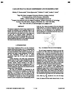
In the collage coding scheme, there are two reasons to optimize the IFS: 1. The transform T is constructed by making the collage residuals d(x, T (x)) smallest; but from the collage theorem (4), the reconstruction residuals d(x, x∗ ) are less than the collage residuals d(x, T (x)) multiplied by a coefficient. The collage residuals are only an upper bound of the reconstruction residuals. So minimizing collage residuals may not result in the minimization of reconstruction residuals. Figure 2 suggests this point, and illustrates the collage images and decoded images of two FICs. Comparing the two FICs, we know that the quality of the collage image of FIC A is better than FIC B; however, the decoded image of FIC A is worse than FIC B. 2. Since the image is tiled by “range block”, each of which is mapped from one of the “domain blocks” as depicted in Figure 1, the combined mappings constitute an IFS in the image as a whole. The IFS minimizing the collage residuals is constructed by individually minimizing the collage residuals of each range block. However, IFS is a system. In coding process, we compute the mappings of the IFS individually minimizing the collage residuals of each range block, but we use them as a whole in the decoding process. So the minimizing residuals of each collage block may not result in the minimization of the reconstruction residuals. Figure 2 illustrates this point.
Enhanced Fractal Image Coding (FIC) with Collage and Reconstruction Residuals
(a)
(b)
(c)
(d)
203
Fig. 2. a) The collage image of FIC A, PSNR = 30.54 dB; b) The decoded image of FIC A, PSNR = 30.0 dB; c) The collage image of FIC B, PSNR = 30.33 dB; d) The decoded image of FIC B, PSNR = 30.16 dB.
So it is possible to optimize the IFS constructed by the collage coding scheme. Although the collage residuals of the new IFS are not smallest, the reconstruction residuals are smaller than those that of the IFS having the smallest collage difference residuals. In the next section, a practical scheme is presented to construct an IFS which is optimal for the decoded image, further to improve the quality performance of the decoded image. 3 THE IFS OPTIMIZATION SCHEME USING RECONSTRUCTION RESIDUALS As discussed in Section 2.2, the IFS can be optimized for the decoded image. In this Section, a scheme is presented to optimize the IFS. The process of optimizing the IFS will be explained in detail. The total procedure is shown in Figure 3.
204
Z. Zhang, Y. Zhao Original image
Domain pool
Traditional FIC
T
Decoded residuals
T'
Correction process
T*
Final FIC
Fig. 3. The total procedure of our scheme
In Figure 3, an original image is firstly encoded by the traditional FIC coder, and its decoded residual image is used to optimize the IFS constructed by traditional FIC. The optimization process is described as follows. We use the decoded image as domain pool and the reconstruction residuals as range pool to construct affine transforms. Note that the partition of the reconstruction residuals is the same as that of the original image; and, for the same position range block, the position of domain block in domain pools is the same. By doing this, we can construct two transformations – T and T ′ . T is constructed for the original image, T ′ is constructed for the reconstruction residual image. Finally, T and T ′ are combined into one transformation T ∗ . Using this method, the new IFS is constructed, which doesn’t make the collage residuals smallest but does make the reconstruction residuals smaller. Our scheme is illustrated in detail in Figure 4. The left box represents the original image R, the middle box represents the reconstruction image and the right box represents the reconstruction residual image. For each range block in the original image R such as Ri , a mapping ωi is found, which maps a larger block Di (domain block) onto Ri . The relation of Ri , Di and ωi can be expressed as follows: (Di , ωi) = arg min k ωi (Di ) − Ri k .
(5)
(Di ,ωi )
Here the blocks Ri and Di are considered as the vectors of pixel intensities. The action of ωi can be described as follows: ωi (Di ) = si ◦ τi ◦ A ◦ Di + oi ◦ 1,
(6)
where si is a scaling factor, oi is an offset, A is the downsampling operator which shrinks the domain block via pixel averaging to match the range block size, τi is a permutation that shuffles the pixel intensities in the downsampled block, and 1 is the block with intensity 1 at every pixel. From (5) and (6), we get (Di , si , oi , τi ) =
arg (Di ,si ,oi ,τi )
min k si ◦ τi ◦ A ◦ Di + oi ◦ 1 − Ri k .
(7)
205
Enhanced Fractal Image Coding (FIC) with Collage and Reconstruction Residuals
So each range block can be represented by a mapping like ωi . All the mappings construct an IFS together, i.e., T = ω1 ◦ ω2 ◦ ω3 ◦ · · · ◦ ωn ,
(8)
where n is the number of range block in a image, ωi is the mapping of the ith range block. From (7) the mapping ωi is constructed and the IFS is constructed by (8). So we can get the reconstruction residuals Re , and Re can be computed by the following equation. Re = R − T n (RandI) n→∞ (9) where T n (RandI) = T (T n−1(RandI)). RandI is an initial arbitrary image. We define T n (RandI) as F ix, which is the fixed point of the IFS because the transform is a contractive transform, and F ix represents the reconstruction image in this paper. So there is the following equation: F ix = T n (RandI) = T (T n−1 (RandI)) = T (F ix)
n → ∞.
(10)
Then another mapping ωi′ is constructed by the domain block F ixi and the reconstruction residual block Re i using the rms metric. Re i is the ith block of reconstruction residual images, which has the same size and the position with the range block Ri . The position of Di is the same as the position of F ixi . Finally, ωi′ is used to adjust ωi . This paper presents that the scale factors of two mappings are added together. The offset parameters of two mappings are added together too. All range blocks do the same operation like range block Ri . For each range block, a new mapping can be constructed. The combined mappings constitute a new IFS in the image as a whole. The newly constructed IFS doesn’t minimize the collage residuals but makes the reconstruction residuals smaller. By doing this, we construct a new IFS. We can see from the following proof that the scheme is reasonable. ωi* Ri
Re _ i
ωi
ω
' i
Di
Original image
Fixi
Decoded difference error image Re
Decoded image
Fig. 4. Use of reconstruction residuals to adjust parameters
From (9) and (10), the relation between the range block Ri and the reconstruction residual block Re i can be expressed as an affine transform: Ri = T n (RandI)i + Re i = ωi (F ixi) + Re
i
n→∞
(11)
206
Z. Zhang, Y. Zhao
where T n (RandI)i is the ith reconstruction image block, Re i is the ith reconstruction residual block. From (6), (10) and (11), we get Ri = si ◦ τi ◦ A ◦ F ixi + oi ◦ 1 + Re i .
(12)
Because of the same positions of domain blocks, the relation between Re i and the same position domain block F ixi in our scheme can be expressed as the following equation: Re i ≈ ωi′ (F ixi ) = s′i ◦ τi ◦ A ◦ F ixi + o′i ◦ 1,
(13)
where ωi′ is the mapping from domain block F ixi to the reconstruction residual block Re i , s′i is the scale factor of the mapping ωi′ and o′i is the offset of the mapping ωi′ . From (12) and (13), we get Ri
≈ = = =
si ◦ τi ◦ A ◦ F ixi + oi ◦ 1 + s′i ◦ τi ◦ A ◦ F ixi + o′i ◦ 1 (si + s′i ) ◦ τi ◦ A ◦ F ixi + (oi + o′i ) ◦ 1 s∗i ◦ τi ◦ A ◦ F ixi + o∗i ◦ 1 ωi∗ (F ixi ),
(14)
where s∗i = si + s′i is the scale factor of the adjusted mapping ωi∗ , o∗i = oi + o′i is the offset factor of the adjusted mapping ωi∗ . All mappings construct a new transform T ∗ as follows: T ∗ = ω1∗ ◦ ω2∗ ◦ · · · ◦ ωn∗ .
(15)
So from the whole image, there is the following equation: T ∗ (F ix) = (T + T ′ )(F ix)
(16)
where T ′ is constructed by mapping ωi′ like Equation (17): T ∗ = ω1′ ◦ ω2′ ◦ · · · ◦ ωn′ .
(17)
From Equations (12–16), the reconstruction residual is used to optimize the traditional IFS. The scale and offset factors are used to adjust the transform, further to find a new IFS. In other words, we use the reconstruction residual information in our scheme. The new IFS doesn’t minimize the collage residuals but makes the reconstruction residuals smaller. Because IFS is a system, we want to adjust each part of the system to make the system optimal. In our scheme, we just use the reconstruction residual information to adjust the IFS constructed by the collage coding scheme. The new IFS is not optimal for the collage because it has been changed by the decoded error information, but the new IFS is optimal for reconstruction image because it has been optimized by the reconstruction residuals information.
Enhanced Fractal Image Coding (FIC) with Collage and Reconstruction Residuals
207
Convergence of the new IFS. In our new IFS, we find some scale factors (about 23 %) are larger than one, and Table 2 shows this point. However, the convergence of our new IFS can be assured because of the “eventual contractivity”. The idea of “eventual contractivity” of the IFS is proposed in papers [7, 17]. That means the scale factor of each block is allowed to be larger than one, but note that not all scale factors are allowed to be larger than one. As long as the product of contractive scale factors (s < 1) outweighs the expansive ones (s > 1), a limit value exists and the IFS is eventual contractivity. Some tests were done to prove this (Table 1). We compulsively make some scale factors larger than one randomly in our tests to test convergence of the IFS. Table 1 suggests when about eighty percent of the scale factors are larger than one, the IFS is still convergence. Image Lena Zebla Baboon Bird Couple Elain
Percentage of scale factor larger than one 85 % 70 % 85 % 80 % 85 % 85 %
Convergence Yes Yes Yes Yes Yes Yes
Table 1. The convergence of IFS with scale factors larger than one
Table 2 shows the percentage of scale factors larger than one of our new IFS in different images. The average percentage of scale factors larger than one of our new IFS is 23 %. So the convergence of our new IFS can be assured. Because the product of contractive scale factors (s < 1) outweighs the expansive ones (s > 1), the new IFS is eventual contractivity, and a limit value of our new IFS exists. Image Lena Zebla Baboon Bird Couple Elain
Percentage of scale factor larger than one 19 % 25 % 23 % 27 % 28 % 16 %
Convergence Yes Yes Yes Yes Yes Yes
Table 2. The convergence of our new IFS with scale factors larger than one
Bit rate. There is no bit increase due to the correction process because the scale and offset coefficients are corrected directly into new ones by the reconstruction residuals, and the range block partition and the domain block position for each range block do not change. Time consuming. The increase in computing time is very small. The most time consuming process of FIC is searching a fitted domain block for each range
208
Z. Zhang, Y. Zhao
block; but for our optimization process, the searching process is not needed. The position of domain block is obtained in the traditional FIC. The increase in computing time is mainly focused on computing the coefficients we needed, which is very small. Preliminary results. We save or transform the parameters s∗i and o∗i of mapping ωi∗ , so there is no change in compression ratio. The quality of our decoded image is better than that of traditional FIC. Experimental results show we can obtain coding gains of 0.3–2.5 dB for 256 × 256 × 8 test images without any change in compression ratio. 4 USING SELECTIVE COLLAGE RESIDUAL BLOCKS TO CORRECT THE IFS In Section 2, we know that the collage residuals are upper bound of reconstruction residuals. Minimizing the collage residuals is not equal to minimizing the reconstruction residuals, so the collage coding scheme lacks the direct control of the reconstruction residuals. In [11], Jean-Luc Dugelay and Allen Gersho give a paradigm using the selective collage residual blocks to control reconstruction residuals. They use VQ to save the collage residual information. In [12], Thomas Freina says that collage residuals can exhibit similar statistical properties as motion compensated errors. For improving the quality of decoded image, in our study, the selective method in [11] is applied to select the collage residual blocks to correct the IFS, and DCT and embedded bit plane coding scheme in motion compensated scheme [13] are used to save this collage residual information. 4.1 How to Modify the IFS Using the Collage Residuals We define Rc = R − T (R)
(18)
Rf = F ix − T (R)
(19)
as the collage residuals. We define as the gap between collage and reconstruction residuals. From (9), we know Re are the reconstruction residuals. Considering that the original image R has been partitioned into a set of N range blocks, we can get the following equation: Rc i = Ri − T (R)i
(20)
where Rc i is the ith collage residual block, Ri is the ith range block and T (R)i is the ith collage block. From (6) we know T (R)i = ωi (Di ) = si ◦ τi ◦ A ◦ Di + oi ◦ 1.
Enhanced Fractal Image Coding (FIC) with Collage and Reconstruction Residuals
209
So by modifying the Ti in the following way, the error of collage for the selective range block will be reduced: ′
T ′ (R)i = ωi′ (Di ) = si ◦ τi ◦ A ◦ Di + oi ◦ 1 + oi
(21)
′
where oi is quantization of the collage residual block Rc i , T ′ is a corrected transformation. 4.2 How to Select Blocks to Correct the IFS The difference residuals of collage and reconstruction of range block Ri can be expressed as follows: Rf i =k T (R)i − T (F ix)i k
(22)
where we have used the attractor property F ix = T (F ix). As in [11], to decrease the residuals between collage and reconstruction, we select the domain Di for correction which provides the maximum value according to the following criterion: Di = arg(max(k si ∗ (A ◦ Di − A ◦ F ixi ) k)).
(23)
Di
Using this criterion, we can find a domain block and we will find which transforms need to be corrected according to the position of domain block. The corrected transforms are those whose range block is partially (or totally) the same with a part of (or total) domain block Di . The corrected vector is (A ◦ Di − A ◦ T (D)i ). Note that we use the DCT and embedded bit plan coding to save the corrected vector. When we use corrected vectors to correct the IFS as given in subsection 4.1, we must add the quantization corrected vectors after having over-sampled it by pixel duplication. 4.3 Bit-Plane Coding The selective corrected vector is transformed by DCT. After DCT, the transform coefficients ci are quantized by a series of successively uniform scalar quantizers with step sizes Tn = 2n , n = m, m − 1, . . . , 1 [13–16]. A significance block map is created at each step size to identify the non-zero regions to be entropy coding (arithmetical coding in this paper). The same entropy coder is also used to code the significance block. The threshold is then halved. The paradigm proposed in Section 4 is shown in detail in Figure 5. The corrected process of the IFS using selected collage residual blocks is given in Figure 5. Each correction of the IFS is based on adding a quantized vectorial shift to some transforms of the IFS. This process does not alter the contractivity. Not only is the collage error reduced, but also the residuals of reconstruction are controlled to decrease.
210
Z. Zhang, Y. Zhao Corrected IFS Y Loop=0
Set the number of correction n
Loop>n ?
N
Select a domain block with (23)
Find corrected transform and corrected vector
Traditional FIC
DCT transform quantization
Original image
Inverse quantization and IDCT
Over-sample by pixel duplication
Add them to the selective transform of IFS and Loop=Loop+1
Fig. 5. Use collage of residuals to correct the IFS
Bit rate. The increase in bit rate due to the correction stage will be given by sindentif ication + n × scorrection , where sindentif ication is the size of the bit needed to indicate if there is a correction or not, n is the number of corrected range blocks, and scorrection is the size of correction vector savage bits. Note that we construct a map to indicate if there is a correction or not, so we can use entropy-coded scheme (arithmetic in this paper) to compress the map and the quantized vector in order to improve the performance of our paradigm. 5 EXPERIMENTAL RESULTS In this section, we will give the comparison results about the schemes proposed in this paper, traditional quadtree scheme and JPEG. In our scheme and quadtree scheme, the following parameter settings are given for our experiments: 3 bits are used to save the orientation information, 5 bits to save scale information and 7 bits to save offset information. As for the positions of domain blocks, it is alterable with the coding process just like Fisher’s scheme. Figure 6 a) shows the original “Lena” image. Figures 6 b) and 6 c) show the decoded “Lena” image using Fisher’s quadtree scheme and our scheme proposed in Section 3, respectively. At the same compression ratio, it can be seen that our scheme achieves higher quality.
Enhanced Fractal Image Coding (FIC) with Collage and Reconstruction Residuals
(a)
211
(b)
(c)
Fig. 6. a) The original “Lena” 256 × 256 × 8 image; b) Decoded “Lena” image using quadtree scheme at CR = 2.01 PSNR = 37.69 dB; c) Decoded “Lena” image using our improved scheme at CR = 2.01 PSNR = 39.57 dB
As the thresholds of collage residuals vary, range block number vs. PSNR curves for the four 256×258×8 images (“Lena”, “Boat”, “Building” and “Girl”) in Figure 7 are obtained with the scheme proposed in Section 3 and with conventional Fisher quadtree scheme. When the saving sizes of scale, offset and orientation information are determined, the compression ratio is dependant on the range block number. Therefore, the paradigm proposed in Section 3 does not change the compression ratio when the range block number is fixed. We use the range block number as the X-axis of Figure 7, which is in favor of our analysis. Our new coder yields better performance compared to the quadtree coder. In our experiments, our coder can achieve coding gains of 0.3–2.5 dB at the same compression ratio to the quadtree scheme. We can see from Figure 7 that the achieved gains increase with the range block number increasing. The smallest gain is 0.3 dB at 2 260 range blocks and the largest gain is 2.5 dB at 10 027 range blocks. The following is our explanation: The number of range blocks means the part number of the IFS. When the part number of the IFS is larger, the system is more complex. It means that there is more possibility of change in the system. We have more opportunity to make our direction to find
212
Z. Zhang, Y. Zhao
the optimal IFS to describe the image that we want to compress. So you can see from Figure 7 that the higher the range block number is, the larger gain of quality we can achieve. The coding results of seven standard tested images “Lena”, “Girl”, “Bridge”, “Building”, “City”, “Seagull”, “Tower” and “Boat” are analyzed to interpret the advantage of our improved scheme proposed in Section 3 over the quadtree scheme and to interpret the universal effect of our scheme referring to Table 3. We choose the following parameter setting for our experiments: The max-partitioned depth is 7; the min-partitioned depth is 4. The tolerance of the collage difference (tol) is 8. Image
Number of range block
Boat Bridge Building City Girl Seagull Tower
6 730 2 788 10 318 7 240 3 181 6 394 2 689
PSNR (dB) Quadtree scheme Our scheme in Section 3 33.69 34.75 35.26 35.50 32.32 34.07 33.55 34.88 35.24 35.63 33.89 34.40 34.25 34.58
Table 3. The comparison coding results of seven standard tested images (tol = 8, min part = 4, max part = 7)
Figure 8 suggests that the scheme proposed in Section 4 can improve the performance of FIC. About 0.3–0.7 dB gains are achieved using the scheme proposed in Section 4. Figure 8 a) uses the “Lena” (256 × 256 × 8) image, and Figure 8 b) uses the “Boat” (256 × 256 × 8) image. We use both paradigms proposed in this paper on Fisher’s quadtree scheme. Comparisons of our proposed schemes and JPEG are given in Figure 9. At lower bit rate, the proposed paradigms have better performance than JPEG; at higher bit rate the proposed paradigms have similar performance with JPEG. Figure 9 a) uses “Lena” (256 × 256 × 8) as tested image, and Figure 9 b) uses “Boat” (256 × 256 × 8) as tested image. 6 CONCLUSIONS In this paper, we present two new schemes to reduce the difference between the fixed-point image and the original image using the reconstruction residuals and collage residuals. The performance of FIC are significantly improved using our schemes. Some rationality proofs are given about our schemes. At the same time, the experimental results suggest strongly that our schemes are effective. We know the traditional IFS through making the collage difference smallest is not optimal. We can get a “better” IFS by adjusting some parameters; however, what we get is not optimal too. How can we get the optimal IFS to describe an image? Many published works such as [9, 10] have proposed alternative solution of
Enhanced Fractal Image Coding (FIC) with Collage and Reconstruction Residuals
42 Proposed scheme Fisher‘s quadtree scheme
40
PSNR (dB)
38
36
34
32
30 2000
4000
6000
8000 Range Block Number
10000
12000
14000
(a)
38
Proposed scheme Fisher‘s quadtree scheme
37
36
PSNR (dB)
35
34
33
32
31
30
2000
3000
4000
5000
6000 7000 Range Block Number
(b)
8000
9000
10000
11000
213
214
Z. Zhang, Y. Zhao 34 Proposed scheme Fisher‘s quadtree scheme 33
32
PSNR (dB)
31
30
29
28
27 2000
3000
4000
5000
6000 7000 Range Block Number
8000
9000
10000
11000
(c) 41 Proposed scheme Fisher‘s quadtree scheme 40
PSNR (dB)
39
38
37
36
35
34 2000
3000
4000
5000 Range Block Number
6000
7000
8000
(d)
Fig. 7. a) Comparison of our scheme proposed in Section 3 and Fisher quadtree scheme using “Lena” 256 × 256 × 8 image; b) Comparison of our scheme proposed in Section 3 and Fisher quadtree scheme using “Boat” 256 × 256 × 8 image; c) Comparison of our scheme proposed in Section 3 and Fisher quadtree scheme using “Building” 256 × 256 × 8 image; d) Comparison of our scheme proposed in Section 3 and Fisher quadtree scheme using “Girl” 256 × 256 × 8 image
Enhanced Fractal Image Coding (FIC) with Collage and Reconstruction Residuals
215
32.5 Proposed scheme Fisher‘s quadtree scheme
32
PSNR (dB)
31.5
31
30.5
30 0.5
0.55
0.6
0.65
0.7
0.75 0.8 Bit Rate (bpp)
0.85
0.9
0.95
1
(a)
29.5
Proposed scheme Fisher‘s quadtree scheme
29
28.5
PSNR (dB)
28
27.5
27
26.5
26
25.5 0.3
0.4
0.5
0.6 0.7 Bit Rate (bpp)
0.8
0.9
1
(b)
Fig. 8. a) Comparison of our proposed scheme in Section 4 and Fisher quadtree scheme using “Lena” 256 × 256 × 8 image; b) Comparison of our scheme proposed in Section 4 and Fisher quadtree scheme using “Boat” 256 × 256 × 8 image
216
Z. Zhang, Y. Zhao
33
Proposed scheme (both) JPEG
32
PSNR (dB)
31
30
29
28
27
0.3
0.4
0.5
0.6 0.7 Bit Rate (bpp)
0.8
0.9
1
(a) 30
Proposed scheme (both) JPEG
29.5 29 28.5
PSNR (dB)
28 27.5 27 26.5 26 25.5 25 0.3
0.4
0.5
0.6 0.7 Bit Rate (bpp)
0.8
0.9
1
(b)
Fig. 9. a) Comparison of our schemes proposed and JPEG using “Lena” 256 × 256 × 8 image; b) Comparison of our proposed schemes and JPEG using “Boat” 256 × 256 × 8 image
Enhanced Fractal Image Coding (FIC) with Collage and Reconstruction Residuals
217
this problem; hovewer, the IFS in those papers is still not optimal. So there are some further investigations, which are valuable to research. Acknowledgements This work was supported in part by National Natural Science Foundation of China (Nos. 90604032 and 60602030), Program for New Century Excellent Talents in University, 973 program (No. 2006CB303104) and Specialized Research Foundation of BJTU. REFERENCES [1] Barnsley, M.: Fractals Everywhere. Academic Press, San Diego, 1988. [2] Kreyzig, E.: Introductory Functional Analysis with Applications. Wiley Press, New York, 1978. [3] Jacquin, A.: Fractal Image Coding Based on a Theory of Iterated Contractive Image Transformations. SPIE Visual Communications and Image Processing, Vol. 1360, 1992, pp. 227–239. [4] Jacquin, A.: Image Coding Based on a Fractal Theory of Iterated Contractive Image Transformations. IEEE Trans. On Image Processing, Vol. 1, 1990, pp. 18–30. [5] Fisher, Y.—Lawrence, A.: Fractal Image Encoding: SBIR Phase 1 Final Report. Tech. Rep., Netrologic, Inc., 1990. [6] Fisher, Y.—Jacobs, E. W.—Boss, R. D.: Fractal Image Compression Using Iterated Transforms. Kluwer Academic Publishers, Norwell MA, 1992. [7] Fisher, Y.: Fractal Image Coding: Theory and Application. Springer Press, New York, 1994. [8] http://www-it.et.tudelfy.nl/ inald/vcdemo/index.htm. [9] Hamzaoui, R.—Hartenstein, H.—Saupe, D.: Local Iterative Improvement of Fractal Image Codes. Image Vis. Comput, Vol. 18, 2000, pp. 565–568. [10] Kang, H.-S.—Chuang, J.-W.: Suboptimal Fractal Coding Scheme Using Iterative Transformation. Optical Engineering, Vol. 40, 2001, pp. 703–712. [11] Dugalay, J.—Gersho, A.: Enhance Fractal Image Coding by Combining IFS and VQ. Inernational Conference on Image Processing, Vol. 3, Oct. 26–29, 1997, pp. 726–729. [12] Freina, T.—Uhl, A.: Predictive Fractal Image Coding: Hybrid Algorithm and Compression of Residuals. Data Compression Conference, March 30–April 1, 1998, pp. 549. [13] Poh, W.—Monro, D. M.: Improved Compression of Motion Compensated Residuals. International Conference on Image Processing, Vol. 1, 2002, pp. 22–25. 725-728. [14] Ordentlich, E.—Weinberger, M.—Seroussi, G.: A Low Complexity Modeling Approach for Embedded Coding of Wavalet Coeffcients. IEEE Tans. Circults and System for Video Tech., Vol. 7, 1997, No. 1, pp. 109–118.
218
Z. Zhang, Y. Zhao
[15] Shapiro, J.: Embedded Image Coding Using Zero Trees of Wavelet Coefficents. IEEE Trans. Circults and System for Video Tech., 1996, pp. 243–250. [16] Said, A.—Pearlman, W. A.: A New Fast and Efficient Image Codec Based on Set Partitioning in Hierarchical Tree. IEEE Trans. Circults and System for Video Tech., 1996, pp. 243–250. [17] Kominek, J.: Convergence of Fractal Encoded Images. Data Compresssion Conference, March 28–30, 1995, pp. 242–251. Zhiyuan Zhang received his B. E. degree from Inner Mongolia University in Mathematics Department in 2002. Since then, he has been working towards the Ph. D. degree in information and communication engineering at the Institute of Information Science, Beijing Jiaotong University. His current research interests include image and video coding, multiple description coding and distributed source coding.
Yao Zhao received his B. E. degree from Fuzhou University in 1989 and M. E. degree from Southeast University in 1992, both in Radio Engineering Department. He received the Ph. D. degree in the Institute of Information Science, Beijing Jiaotong University (BJTU) in 1996. He became an associate professor with NJTU in 1998 and became a professor in 2001. From 2001 to 2002, he worked as a Senior Research Fellow in Information and Communication Theory Group, Faculty of Information Technology and Systems, Delft University of Technology, The Netherlands. He is now the director of Institute of Information Science, Beijing Jiaotong University. He is an editor of national journal Signal Acquisition and Processing, and associate editor of International Journal of Innovative Computing, Information and Control. His research interests include image/video coding, fractals, digital watermarking and content-based image retrieval. He has published more than 90 papers in international journals and conferences. Now he is leading several national research projects from 973 Program, National Science Foundation of China and Fok Ying Tong Education Foundation.